DE102018122516A1 - Nasal cannula with improved, also asymmetrical flow guidance - Google Patents
Nasal cannula with improved, also asymmetrical flow guidance Download PDFInfo
- Publication number
- DE102018122516A1 DE102018122516A1 DE102018122516.4A DE102018122516A DE102018122516A1 DE 102018122516 A1 DE102018122516 A1 DE 102018122516A1 DE 102018122516 A DE102018122516 A DE 102018122516A DE 102018122516 A1 DE102018122516 A1 DE 102018122516A1
- Authority
- DE
- Germany
- Prior art keywords
- opening
- distribution channel
- formation
- distribution
- nasal cannula
- Prior art date
- Legal status (The legal status is an assumption and is not a legal conclusion. Google has not performed a legal analysis and makes no representation as to the accuracy of the status listed.)
- Withdrawn
Links
Images


Classifications
-
- A—HUMAN NECESSITIES
- A61—MEDICAL OR VETERINARY SCIENCE; HYGIENE
- A61M—DEVICES FOR INTRODUCING MEDIA INTO, OR ONTO, THE BODY; DEVICES FOR TRANSDUCING BODY MEDIA OR FOR TAKING MEDIA FROM THE BODY; DEVICES FOR PRODUCING OR ENDING SLEEP OR STUPOR
- A61M16/00—Devices for influencing the respiratory system of patients by gas treatment, e.g. ventilators; Tracheal tubes
- A61M16/06—Respiratory or anaesthetic masks
- A61M16/0666—Nasal cannulas or tubing
- A61M16/0672—Nasal cannula assemblies for oxygen therapy
-
- A—HUMAN NECESSITIES
- A61—MEDICAL OR VETERINARY SCIENCE; HYGIENE
- A61M—DEVICES FOR INTRODUCING MEDIA INTO, OR ONTO, THE BODY; DEVICES FOR TRANSDUCING BODY MEDIA OR FOR TAKING MEDIA FROM THE BODY; DEVICES FOR PRODUCING OR ENDING SLEEP OR STUPOR
- A61M16/00—Devices for influencing the respiratory system of patients by gas treatment, e.g. ventilators; Tracheal tubes
- A61M16/08—Bellows; Connecting tubes ; Water traps; Patient circuits
- A61M16/0816—Joints or connectors
-
- A—HUMAN NECESSITIES
- A61—MEDICAL OR VETERINARY SCIENCE; HYGIENE
- A61M—DEVICES FOR INTRODUCING MEDIA INTO, OR ONTO, THE BODY; DEVICES FOR TRANSDUCING BODY MEDIA OR FOR TAKING MEDIA FROM THE BODY; DEVICES FOR PRODUCING OR ENDING SLEEP OR STUPOR
- A61M2205/00—General characteristics of the apparatus
- A61M2205/60—General characteristics of the apparatus with identification means
- A61M2205/6045—General characteristics of the apparatus with identification means having complementary physical shapes for indexing or registration purposes
-
- A—HUMAN NECESSITIES
- A61—MEDICAL OR VETERINARY SCIENCE; HYGIENE
- A61M—DEVICES FOR INTRODUCING MEDIA INTO, OR ONTO, THE BODY; DEVICES FOR TRANSDUCING BODY MEDIA OR FOR TAKING MEDIA FROM THE BODY; DEVICES FOR PRODUCING OR ENDING SLEEP OR STUPOR
- A61M2206/00—Characteristics of a physical parameter; associated device therefor
- A61M2206/10—Flow characteristics
- A61M2206/20—Flow characteristics having means for promoting or enhancing the flow, actively or passively
Landscapes
- Health & Medical Sciences (AREA)
- Emergency Medicine (AREA)
- Otolaryngology (AREA)
- Pulmonology (AREA)
- Engineering & Computer Science (AREA)
- Anesthesiology (AREA)
- Biomedical Technology (AREA)
- Heart & Thoracic Surgery (AREA)
- Hematology (AREA)
- Life Sciences & Earth Sciences (AREA)
- Animal Behavior & Ethology (AREA)
- General Health & Medical Sciences (AREA)
- Public Health (AREA)
- Veterinary Medicine (AREA)
- Infusion, Injection, And Reservoir Apparatuses (AREA)
Abstract
Nasenbrille (10) zur nasalen Versorgung eines Patienten mit Therapiegas, umfassend ein Verteilkanalbauteil (12) mit einem Verteilkanal (20), welcher längs einer virtuellen, ihn zentral durchsetzenden Verteilbahn (V) verläuft, wobei die Verteilbahn (V) eine Längsrichtung definiert, wobei der Verteilkanal (20) zwei Abzweigöffnungen (26b, 28b) aufweist, wobei ausgehend von jeder Abzweigöffnung (26b, 28b) je ein Versorgungskanal (26, 28) zur Versorgung des Patienten mit Therapiegas vom Verteilkanal (20) abzweigt, wobei der Verteilkanal (20) zusätzlich zu den Abzweigöffnungen (26b, 28b) zwei mit Abstand von den Abzweigöffnungen (26b, 28b) angeordnete Kopplungsöffnungen (22, 24) aufweist, wobei die Nasenbrille (10) einen Stopfen (14) umfasst, durch welchen eine der beiden Kopplungsöffnungen (22, 24) als Verschlussöffnung (22) durch den Stopfen (14) für eine Gasdurchströmung verschließbar ist und wobei eine weitere der beiden Kopplungsöffnungen (22, 24) als Zufuhröffnung (24) zum Anschluss einer Gas-Zufuhrleitung (16, 18) an den Verteilkanal (20) ausgebildet ist.Erfindungsgemäß ist vorgesehen, dass der Stopfen (14) eine Strömungsleitformation (42) mit einer freiliegenden Strömungsleitfläche (44) aufweist, wobei die Strömungsleitfläche (44) in einem Bezugszustand, in dem der Stopfen (14) bestimmungsgemäß die Verschlussöffnung (22) verschließend an der Nasenbrille (10) angeordnet ist, im Verteilkanal (20) im Längserstreckungsbereich wenigstens einer Abzweigöffnung (26b, 28b) angeordnet ist und derart zur Verteilbahn (V) angestellt ist, dass sie im Verteilkanal (20) von der Zufuhröffnung (24) her längs der Verteilbahn (V) anströmendes Therapiegas zu wenigstens einer der Abzweigöffnungen (26b, 28b) hin umlenkt.Nasal spectacles (10) for nasally supplying a patient with therapeutic gas, comprising a distribution channel component (12) with a distribution channel (20), which runs along a virtual distribution path (V) penetrating it centrally, the distribution path (V) defining a longitudinal direction, wherein the distribution channel (20) has two branch openings (26b, 28b), starting from each branch opening (26b, 28b) a supply channel (26, 28) for supplying the patient with therapeutic gas branches off from the distribution channel (20), the distribution channel (20 ) in addition to the branch openings (26b, 28b) has two coupling openings (22, 24) arranged at a distance from the branch openings (26b, 28b), the nasal cannula (10) comprising a stopper (14) through which one of the two coupling openings ( 22, 24) can be closed as a closure opening (22) by the stopper (14) for a gas flow, and another of the two coupling openings (22, 24) as a supply opening (24) for connecting a gas supply line (16, 18) to the distribution channel (20). According to the invention, the plug (14) has a flow guide formation (42) with an exposed flow guide surface (44), the flow guide surface (44) in a reference state, in which the stopper (14) is arranged to close the closure opening (22) on the nasal cannula (10), is arranged in the distribution channel (20) in the longitudinal extension region of at least one branch opening (26b, 28b) and thus to the distribution path (V ) is employed so that it deflects therapeutic gas flowing along the distribution path (V) in the distribution channel (20) from the supply opening (24) to at least one of the branch openings (26b, 28b).
Description
Die vorliegende Anmeldung betrifft eine Nasenbrille zur nasalen Versorgung eines Patienten mit Therapiegas, umfassend ein Verteilkanalbauteil mit einem Verteilkanal, welcher längs einer virtuellen, ihn zentral durchsetzenden Verteilbahn verläuft, wobei die Verteilbahn eine Längsrichtung definiert, wobei der Verteilkanal zwei Abzweigöffnungen aufweist, wobei ausgehend von jeder Abzweigöffnung je ein Versorgungskanal zur Versorgung des Patienten mit Therapiegas vom Verteilkanal abzweigt, wobei der Verteilkanal zusätzlich zu den Abzweigöffnungen zwei mit Abstand von den Abzweigöffnungen angeordnete Kopplungsöffnungen aufweist, wobei die Nasenbrille einen Stopfen umfasst, durch welchen eine der beiden Kopplungsöffnungen als Verschlussöffnung durch den Stopfen für eine Gasdurchströmung verschließbar ist und wobei eine weitere der beiden Kopplungsöffnungen als Zufuhröffnung zum Anschluss einer Gas-Zufuhrleitung an den Verteilkanal ausgebildet ist.The present application relates to nasal cannula for the nasal supply of a patient with therapeutic gas, comprising a distribution channel component with a distribution channel which runs along a virtual distribution path passing through it centrally, the distribution path defining a longitudinal direction, the distribution channel having two branch openings, starting from each Branch opening each has a supply channel for supplying the patient with therapeutic gas from the distribution channel, the distribution channel having two coupling openings arranged at a distance from the branch openings in addition to the branch openings, the nasal cannula comprising a stopper through which one of the two coupling openings serves as a closure opening through the stopper for a gas flow can be closed and another of the two coupling openings is designed as a supply opening for connecting a gas supply line to the distribution channel.
Eine solche Nasenbrille ist aus der
Um die Kopplungsöffnungen am bekannten Verteilkanalbauteil zur Ankopplung des Stopfens und einer Gas-Zufuhrleitung ausreichend sicher ausbilden zu können, verläuft das Verteilkanalbauteil längs der Verteilbahn beiderseits der Abzweigöffnungen über eine verhältnismäßig große Strecke. Nachteilig an der bekannten Nasenbrille ist, dass im Bereich zwischen der durch den Stopfen als Verschlussöffnung genutzten Kopplungsöffnung und den Abzweigöffnungen ein verhältnismäßig großer Totraum gebildet ist, in welchem Therapiegas bei einer Versorgung eines Patienten unkontrolliert strömt und verwirbelt, was zu unvorteilhaft unvorhersagbaren Gasaustrittsverhältnissen an den Abzweigöffnungen führt.In order to be able to form the coupling openings on the known distribution channel component for coupling the plug and a gas supply line sufficiently securely, the distribution channel component runs along the distribution path on both sides of the branch openings over a relatively large distance. A disadvantage of the known nasal cannula is that a relatively large dead space is formed in the area between the coupling opening used by the stopper as a closure opening and the branch openings, in which therapeutic gas flows and swirls in an uncontrolled manner when a patient is being cared for, which leads to disadvantageously unpredictable gas outlet conditions at the branch openings leads.
Es ist daher Aufgabe der vorliegenden Anmeldung, die eingangs genannte Nasenbrille derart zu verbessern, dass trotz Verwendung eines Stopfens in einer als Verschlussöffnung genutzten Kopplungsöffnung sich die Strömungsverhältnisse im Verteilkanal definierter als bisher ausbilden und somit zum einen geringere Strömungsverluste im Verteilkanal auftreten und zum anderen ein definierteres Ausströmen von Therapiegas durch die Abzweigöffnungen zum Patienten hin erfolgt.It is therefore the object of the present application to improve the nasal cannula mentioned at the outset in such a way that, despite the use of a stopper in a coupling opening used as a closure opening, the flow conditions in the distribution channel are more defined than before and thus on the one hand there are lower flow losses in the distribution channel and on the other hand a more defined one Therapy gas flows out through the branch openings to the patient.
Diese Aufgabe löst die vorliegende Erfindung durch eine Nasenbrille der eingangs genannten Art, bei welcher der Stopfen eine Strömungsleitformation mit einer freiliegenden Strömungsleitfläche aufweist, wobei die Strömungsleitfläche in einem Bezugszustand, in dem der Stopfen bestimmungsgemäß die Verschlussöffnung verschließend an der Nasenbrille angeordnet ist, im Verteilkanal im Längserstreckungsbereich wenigstens einer Abzweigöffnung angeordnet ist und derart zur Verteilbahn angestellt ist, dass sie im Verteilkanal von der Zufuhröffnung her längs der Verteilbahn anströmendes Therapiegas zu wenigstens einer der Abzweigöffnungen hin umlenkt.This object is achieved by the nasal cannula of the type mentioned at the outset, in which the stopper has a flow guide formation with an exposed flow guide surface, the flow guide surface in a reference state in which the stopper is arranged to close the closure opening on the nasal cannula in the distribution channel in the The longitudinal extension region of at least one branch opening is arranged and is positioned in relation to the distribution path in such a way that it deflects therapeutic gas flowing along the distribution path from the supply opening to at least one of the branch openings in the distribution channel.
Sofern in der vorliegenden Anmeldung im Einzelfall nichts Abweichendes ausgesagt ist, ist die Nasenbrille der vorliegenden Anmeldung in dem oben bezeichneten Bezugszustand beschrieben.Unless otherwise stated in the individual application in the present application, the nasal cannula of the present application is described in the reference state described above.
Die freiliegende Strömungsleitfläche der Strömungsleitformation, welche im Bezugszustand dem von der Zufuhröffnung her anströmenden Therapiegas zugewandt und durch diese benetzbar ist, kann das von der Zufuhröffnung her anströmende Therapiegas möglichst verlustfrei zu der Abzweigöffnung hin umlenken, in deren Längserstreckungsbereich die Strömungsleitfläche angeordnet ist. Zur Erfüllung dieser Umlenkfunktion ist die Strömungsleitfläche relativ zur Verteilbahn angestellt, d. h. die Verteilbahn schließt mit der Strömungsleitfläche einen Winkel ein. Im einfachsten Fall kann die Strömungsleitfläche eine ebene oder wenigstens eine abschnittsweise ebene Fläche sein. Für eine besonders verlustfreie Umlenkung der Therapiegasströmung ist die Strömungsleitfläche jedoch bevorzugt eine wenigstens abschnittsweise gekrümmte Fläche. Die Strömungsleitfläche kann längs ihrer gesamten Längserstreckung längs der Verteilbahn gekrümmt ausgebildet sein.The exposed flow guide surface of the flow guide formation, which in the reference state faces the therapeutic gas flowing in from the supply opening and can be wetted by it, can deflect the therapeutic gas flowing in from the supply opening as far as possible loss-free towards the branch opening, in the longitudinal extension area of which the flow directing surface is arranged. To fulfill this deflection function, the flow guide surface is set relative to the distribution path, i. H. the distribution path forms an angle with the flow guide surface. In the simplest case, the flow guide surface can be a flat surface or at least a flat surface in sections. For a particularly loss-free deflection of the therapy gas flow, however, the flow guide surface is preferably an at least sectionally curved surface. The flow guide surface can be curved along its entire longitudinal extent along the distribution path.
In der Regel ist eine Umlenkung der zunächst längs der Verteilbahn verlaufenden Therapiegasströmung zur Abzweigöffnung um etwa 90°, also etwa im rechten Winkel, wünschenswert. Hierfür ist es zur möglichst verlustfreien Umlenkung vorteilhaft, wenn die Strömungsleitfläche eine konkave Krümmung aufweist. Für eine möglichst verlustfreie Umlenkung der Therapiegasströmung im Verteilkanalbauteil ist eine möglichst kontinuierlich gekrümmte Strömungsleitfläche von Vorteil, weshalb die Strömungsleitfläche bevorzugt über ihre gesamte Erstreckungslänge eine konkave Krümmung aufweisen kann. Um die Umlenkung um 90° ausgehend von der Verteilbahn zur Abzweigöffnung hin zu erreichen, ist die Strömungsleitfläche vorzugsweise um eine zur Verteilbahn orthogonale Krümmungsachse wenigstens abschnittsweise konkav gekrümmt.As a rule, it is desirable to deflect the therapeutic gas flow initially running along the distribution path to the branch opening by approximately 90 °, that is to say at approximately a right angle. For this purpose, it is advantageous for the deflection to be as loss-free as possible if the flow guide surface has a concave curvature. For a loss-free deflection of the therapeutic gas flow in the distribution channel component, one is as continuous as possible curved flow guide surface is advantageous, which is why the flow guide surface can preferably have a concave curvature over its entire length. In order to achieve the deflection by 90 ° starting from the distribution path to the branch opening, the flow guide surface is preferably concavely curved at least in sections around an axis of curvature orthogonal to the distribution path.
Die Strömungsleitfläche kann, um an beiden Abzweigöffnungen möglichst einheitliche Therapiegas-Mengenströme bereitzustellen, unterschiedlich gekrümmte Abschnitte aufweisen. Da die Abzweigöffnungen in der Regel unterschiedliche Entfernung zu der Strömungsleitfläche aufweisen, ist die Erzielung betragsmäßig gleicher Mengenströme in beiden Abzweigöffnungen schwierig, aber gemäß einer bevorzugten Weiterbildung etwa dadurch erreichbar, dass die Strömungsleitfläche längs der Verteilbahn zwei konkav gekrümmte Abschnitte aufweist, welche zwischen sich einen konvex gekrümmten Abschnitt aufweisen. Bevorzugt weist die Strömungsleitfläche nur diese Abschnitte auf und besteht aus diesen. Eine derart mehrfach unterschiedlich gekrümmte Strömungsleitfläche ist bevorzugt in jedem Abschnitt um eine zur Verteilbahn orthogonale Krümmungsachse gekrümmt. In Breitenrichtung des Verteilkanals, also orthogonal zur Verteilbahn ist die Strömungsleitfläche bevorzugt ungekrümmt.The flow guide surface can have differently curved sections in order to provide as uniform as possible therapeutic gas flow rates at both branch openings. Since the branch openings are generally at different distances from the flow guide surface, it is difficult to achieve the same volume flows in both branch openings, but according to a preferred development it can be achieved, for example, by the flow guide surface having two concavely curved sections along the distribution path, which have a convex between them have curved section. The flow guide surface preferably has only these sections and consists of these. Such a flow guiding surface, which is curved several times differently, is preferably curved in each section around an axis of curvature orthogonal to the distribution path. In the width direction of the distribution channel, that is to say orthogonally to the distribution path, the flow guide surface is preferably non-curved.
Auch dann, wenn die Strömungsleitfläche um die genannte zur Verteilbahn orthogonale Krümmungsachse gekrümmt ist, können sich in den wandnahen Bereichen des Verteilkanals Wirbel ausbilden, wenn die Strömungsleitfläche beispielsweise mit einem Winkel unter Bildung einer Ecke in die Wand des Verteilkanals mündet. Zur Vermeidung derartiger unerwünschter Wirbelbildungen ist gemäß einer bevorzugten Weiterbildung der vorliegenden Erfindung vorgesehen, dass die um eine zur Verteilbahn orthogonale Krümmungsachse konkav gekrümmte Strömungsleitfläche auch um eine längs der Verteilbahn verlaufende Krümmungsachse gekrümmt ist. Bevorzugt weist diese Strömungsleitfläche nur konkav gekrümmte Flächenbereiche, jedoch keine konvex gekrümmten Flächenbereiche auf.Even if the flow guide surface is curved around the said axis of curvature orthogonal to the distribution path, vortices can form in the regions of the distribution channel near the wall if the flow guide surface opens into the wall of the distribution channel, for example at an angle, forming a corner. In order to avoid such undesirable vortex formation, it is provided according to a preferred development of the present invention that the flow guide surface which is concavely curved about an axis of curvature orthogonal to the distribution path is also curved around an axis of curvature running along the distribution path. This flow guide surface preferably has only concavely curved surface areas, but no convexly curved surface areas.
Grundsätzlich kann das Therapiegas aus den Abzweigöffnungen unmittelbar nach Durchtritt durch diese im freien Strahl vom Verteilkanalbauteil zum Patienten, welcher die Nasenbrille trägt, hin ausströmen. Üblicherweise wird der Verteilkanal jedoch mit gewisser Entfernung von den Nasenöffnungen getragen. Zur gezielten Zuleitung von Therapiegas weist die Nasenbrille die Versorgungskanäle auf, welche ausgehend von den Abzweigöffnungen vom Verteilkanalbauteil abstehen. Diese Versorgungskanäle reichen in der Therapie an die Nasenöffnungen eines Patienten heran oder verlaufen sogar durch die Nasenöffnungen hindurch ein Stück weit in die Nasenhöhlen hinein. Von jeder Abzweigöffnung geht je ein Versorgungskanal aus. Die Versorgungskanäle können identisch bzw. zu einer die Verteilbahn zwischen den Abzweigöffnungen orthogonal schneidenden Symmetrieachse spiegelsymmetrisch ausgebildet sein.In principle, the therapeutic gas can flow out of the branch openings immediately after passing through them in the free jet from the distribution channel component to the patient who wears the nasal cannula. Usually, however, the distribution channel is carried a certain distance from the nostrils. For the targeted supply of therapeutic gas, the nasal cannula has the supply channels which, starting from the branch openings, protrude from the distribution channel component. In therapy, these supply channels reach the nostrils of a patient or even run a little way into the nasal cavities through the nostrils. A supply channel extends from each branch opening. The supply channels can be identical or mirror-symmetrical to an axis of symmetry intersecting the distribution path between the branch openings.
Die Strömungsleitfläche verläuft wenigstens im Längserstreckungsbereich, also im Erstreckungsbereich längs der Verteilbahn, der der jeweiligen Verschlussöffnung näher gelegenen Abzweigöffnung. Dadurch kann sichergestellt werden, dass die Strömungsleitfläche eine Therapiegasströmung wenigstens zu dieser der Verschlussöffnung näher gelegenen Abzweigöffnung wirkungsvoll und gezielt umlenken kann. Es soll jedoch nicht ausgeschlossen sein, dass sich die Strömungsleitfläche auch in den Längserstreckungsbereich der der jeweiligen Verschlussöffnung ferner liegenden Abzweigöffnung hinein erstreckt oder über diese sogar vollständig hinweg verläuft. In diesem Falle wird die Umlenkung der von der Zufuhröffnung längs der Verteilbahn anströmenden Therapiegasströmung über einen langen Bereich des Verteilkanals schonend und mit nur geringen Verlusten erreicht.The flow guide surface runs at least in the longitudinal extent region, that is to say in the extension region along the distribution path, of the branch opening closer to the respective closure opening. This can ensure that the flow guide surface can effectively and specifically deflect a therapy gas flow at least to this branch opening closer to the closure opening. However, it should not be ruled out that the flow guiding surface also extends into the longitudinal extent of the branch opening further away from the respective closure opening or even runs completely over it. In this case, the deflection of the therapeutic gas flow flowing in from the supply opening along the distribution path over a long area of the distribution channel is achieved gently and with only slight losses.
Die wenigstens abschnittsweise konkave oder/und konvexe Krümmung der Strömungsleitfläche um eine jeweilige zur Verteilbahn orthogonale Krümmungsachse kann sich betragsmäßig längs ihres Verlaufs ändern. Bevorzugt nimmt die konkave Krümmung eines konkav gekrümmten Abschnitts der Strömungsleitfläche um eine zur Verteilbahn orthogonale Krümmungsachse mit zunehmender Annäherung an die zugeordnete Abzweigöffnung zu, d. h. der von der genannten Krümmungsachse ausgehende Krümmungsradius wird mit zunehmender Annäherung der Strömungsleitfläche an die der Strömungsleitfläche zugeordnete Abzweigöffnung kürzer.The amount of concavity and / or convex curvature at least in sections of the flow guide surface about a respective axis of curvature orthogonal to the distribution path can change in magnitude along its course. The concave curvature of a concavely curved section of the flow guide surface about an axis of curvature orthogonal to the distribution path increases with increasing proximity to the assigned branch opening, i. H. the radius of curvature emanating from the mentioned axis of curvature becomes shorter as the flow guide surface approaches the branch opening assigned to the flow guide surface.
Zur Einleitung von Therapiegas in den Verteilkanal des Verteilkanalbauteils weist die Nasenbrille bevorzugt einen Anschlussstutzen auf, welcher zum Anschluss einer Gas-Zufuhrleitung in die Zufuhröffnung einführbar ist. Zur Vermeidung von Wirbel bildenden Stufen im Verteilkanal bzw. längs einer die Therapiegasströmung im Verteilkanalbauteil führenden Wandung, kann gemäß einer bevorzugten Weiterbildung der vorliegenden Erfindung eine eine Gasströmung durch den Anschlussstutzen leitende Innenfläche des Anschlussstutzens bei bestimmungsgemäßer, betriebsbereiter Anordnung an der Nasenbrille mit der Strömungsleitfläche des Stopfens eine kontinuierliche strömungsleitende Fläche bilden. An der Stoßstelle der Innenfläche des Anschlussstutzens und der Strömungsleitfläche entsteht eine unvermeidliche Fuge, an der jedoch dann keine Wirbel entstehen, wenn die Innenfläche und die Strömungsleitfläche eine gemeinsame, über die Fuge hinweg bündige strömungsleitende Fläche bilden. Die gemeinsame kontinuierliche strömungsleitende Fläche ist bevorzugt an der genannten Fuge stufen- und knickfrei.In order to introduce therapeutic gas into the distribution channel of the distribution channel component, the nasal cannula preferably has a connecting piece which can be inserted into the supply opening for connecting a gas supply line. To avoid vortex-forming steps in the distribution channel or along a wall guiding the therapeutic gas flow in the distribution channel component, according to a preferred development of the present invention, an inner surface of the connection piece which conducts a gas flow through the connection piece with the intended, ready-to-use arrangement on the nasal cannula with the flow guide surface of the stopper form a continuous flow-guiding surface. An inevitable joint is created at the joint of the inner surface of the connecting piece and the flow guide surface, but no vortices are created at the joint if the inner surface and the flow guide surface form a common flow-guiding surface that is flush across the joint. The Common continuous flow-guiding surface is preferably free of steps and kinks at the joint mentioned.
Zur Erleichterung der korrekten Anordnung von Stopfen und Anschlussstutzen relativ zueinander kann gemäß einer Weiterbildung der vorliegenden Erfindung vorgesehen sein, dass der Stopfen eine Formschlussformation aufweist und dass der Anschlussstutzen eine Formschlussgegenformation aufweist, wobei die Formschlussformation und die Formschlussgegenformation im betriebsbereiten Zustand miteinander in Formschlusseingriff stehen. Der Stopfen und der Anschlussstutzen können zwar an ihrer bezogen auf die Verteilbahn im betriebsbereiten Zustand radial äußere Außenseite eine konisch-kreiskegelförmige oder eine kreiszylindrische Außenwand, an ihrer radial inneren Innenfläche jedoch eine die Strömung nach radial außen begrenzende Wandung aufweisen, welche keinen Kreisquerschnitt aufweist. Dann, wenn die oben genannte kontinuierliche strömungsleitende Fläche gemeinsam durch die Innenfläche des Anschlussstutzens und die Strömungsleitfläche gebildet werden soll, kommt es besonders auf die richtige relative Anordnung von Stopfen und Anschlussstutzen zueinander an. Diese richtige relative Anordnung kann durch die genannten Formationen: Formschlussformation und Formschlussgegenformation, sicher erreicht werden. Um sicherzustellen, dass eine Fehlstellung von Anschlussstutzen und Stopfen relativ zueinander im betriebsbereiten Zustand ausgeschlossen ist, stehen die Formschlussformation und die Formschlussgegenformation vorzugsweise nur im betriebsbereiten Zustand miteinander in Formschlusseingriff.In order to facilitate the correct arrangement of the plug and connecting piece relative to one another, it can be provided according to a further development of the present invention that the plug has a positive locking formation and that the connecting piece has a positive locking counterformation, the positive locking formation and the positive locking counterformation being in positive locking engagement with one another in the operational state. Although the plug and the connecting piece can have a conical-circular-conical or a circular-cylindrical outer wall on their radially outer outer side in relation to the distribution path in the ready-to-operate state, on their radially inner inner surface, however, they can have a wall which limits the flow radially outward and has no circular cross section. If the above-mentioned continuous flow-guiding surface is to be formed jointly by the inner surface of the connecting piece and the flow-guiding surface, the correct relative arrangement of the plug and connecting piece to one another is particularly important. This correct relative arrangement can be reliably achieved by the formations mentioned: form-fit formation and form-fit counter-formation. In order to ensure that a misalignment of the connecting piece and plug relative to one another in the ready-to-operate state is excluded, the positive-locking formation and the positive-locking counter-formation are preferably in positive-locking engagement with one another only in the ready-to-operate state.
Die Formschlussformation und die Formschlussgegenformation sind bevorzugt nach dem Schlüssel-Schloss-Prinzip ausgebildet. Hierzu kann eine der Formationen aus Formschlussformation und Formschlussgegenformation einen Vorsprung aufweisen und kann die jeweils andere Formation eine Ausnehmung aufweisen, in welche der Vorsprung nur dann eingeführt werden kann, wenn der Anschlussstutzen und der Stopfen relativ zueinander richtig orientiert sind, insbesondere hinsichtlich ihrer Winkelorientierung um die Verteilbahn relativ zueinander richtig orientiert sind.The interlocking formation and the interlocking counterformation are preferably designed according to the key-lock principle. For this purpose, one of the formations of form-fitting formation and form-fitting counter-formation can have a projection and the other formation can have a recess into which the projection can only be inserted if the connecting piece and the plug are correctly oriented relative to one another, in particular with regard to their angular orientation around the Distribution path are correctly oriented relative to each other.
Durch die Formschlussformation und die Formschlussgegenformation wird eine Verdrehsicherung von Anschlussstutzen und Stopfen relativ zueinander erreicht. Bei hergestelltem Formschlusseingriff ist eine Relativverdrehung von Stopfen und Anschlussstutzen relativ zueinander verhindert.The interlocking formation and the interlocking counterformation ensure that the connecting piece and plug are prevented from rotating relative to one another. When the positive engagement is made, a relative rotation of the plug and the connecting piece relative to one another is prevented.
Da der Formschlusseingriff in der Regel im Verteilkanalbauteil hergestellt wird, und zwar an einem von einem Pflegepersonal bzw. vom behandelnden Arzt nicht einsehbaren Ort im Verteilkanalbauteil, kann eine oder können beide Formationen eine Einführhilfe zur Herstellung des Formschlusseingriffs aufweisen. So kann eine einen Vorsprung aufweisende Formation aus Formschlussformation und die Formschlussgegenformation zum frei auskragenden Ende hin verjüngt sein. Zusätzlich oder alternativ kann eine den Vorsprung aufnehmende Ausnehmung als die jeweils andere Formation aus Formschlussformation und Formschlussgegenformation vom Einführlängsende her in Einführrichtung des Vorsprungs verjüngend ausgebildet sein.Since the positive engagement is generally produced in the distribution channel component, and specifically at a location in the distribution channel component that cannot be seen by nursing staff or the attending physician, one or both formations can have an insertion aid for producing the positive engagement. For example, a formation of form-fit formation that has a projection and the form-fit counter-formation can be tapered toward the freely projecting end. Additionally or alternatively, a recess receiving the projection can be designed to taper in the direction of insertion of the projection from the longitudinal insertion end as the other formation of form-fitting formation and form-fitting counter-formation.
Nicht nur die relative Anordnung von Stopfen und Anschlussstutzen sind für die korrekte Funktion der hier diskutierten Nasenbrille vorteilhaft, sondern auch eine korrekte Lage des Anschlussstutzens relativ zum Verteilkanalbauteil. Eine korrekte Lage des Anschlussstutzens relativ zum Verteilkanalbauteil kann dadurch erreicht werden, dass der Anschlussstutzen eine Anordnungsformation aufweist und dass das Verteilkanalbauteil im Bereich der Zufuhröffnung eine Anordnungsgegenformation aufweist, wobei die Anordnungsformation und die Anordnungsgegenformation im betriebsbereiten Zustand miteinander in Formschlusseingriff stehen. Dieser Formschlusseingriff verhindert eine Verlagerung von Anschlussstutzen und Verteilkanalbauteil relativ zueinander aus der hergestellten korrekten Relativanordnung, insbesondere um die Verteilbahn herum.Not only the relative arrangement of the plugs and connecting pieces are advantageous for the correct functioning of the nasal cannula discussed here, but also a correct position of the connecting pieces relative to the distribution channel component. A correct position of the connection piece relative to the distribution duct component can be achieved in that the connection duct has an arrangement formation and that the distribution duct component has a counter arrangement information in the area of the feed opening, the arrangement formation and the arrangement counter formation being in positive engagement with one another in the ready-to-use state. This positive engagement prevents displacement of the connecting piece and the distribution duct component relative to one another from the correct relative arrangement produced, in particular around the distribution path.
Wiederum ist zum Ausschluss einer Fehlstellung von Anschlussstutzen und Verteilkanalbauteil bevorzugt, dass der beschriebene Formschlusseingriff zwischen Anordnungsformation und Anordnungsgegenformation nur im betriebsbereiten Zustand der Nasenbrille besteht bzw. nur bei einer zum betriebsbereiten Zustand führenden Montage der Nasenbrille herstellbar ist. Es gilt für die möglichen Ausgestaltungen der Anordnungsformation und der Anordnungsgegenformation das oben zur Formschlussformation und Formschlussgegenformation Gesagte entsprechend mit der Maßgabe, dass das für die Formschlussformation Gesagte für die Anordnungsformation gilt und dass das für die Formschlussgegenformation Gesagte für die Anordnungsgegenformation gilt. Daher kann eine Formation aus Anordnungsformation und Anordnungsgegenformation einen Vorsprung aufweisen und die jeweils andere Formation kann eine Ausnehmung aufweisen.Again, in order to rule out a malposition of the connecting piece and distribution channel component, it is preferred that the positive engagement described between the arrangement formation and the arrangement counterformation only exists when the nasal cannula is ready for operation or can only be produced when the nasal cannula is assembled and ready for use. For the possible configurations of the arrangement formation and the arrangement counterformation, what has been said above regarding the form-fit formation and form-fit counter-formation applies accordingly, with the proviso that what has been said for the form-fit formation applies to the arrangement formation and that what has been said for the form-fit counter formation applies to the arrangement counter-formation. Therefore a Formation of arrangement formation and arrangement counterformation have a projection and the respective other formation can have a recess.
Da das Verteilkanalbauteil den Anschlussstutzen in der Regel radial außen umgibt oder/und verhältnismäßig dünnwandig ausgebildet ist, weist bevorzugt das Verteilkanalbauteil den Vorsprung und der Anschlussstutzen die Ausnehmung auf. Während eine Formation aus Formschlussformation und Formschlussgegenformation bevorzugt ein Vorsprung ist, welcher von der ihn tragenden Struktur parallel zur Verteilbahn auskragt, ist der Vorsprung einer Formation aus Anordnungsformation und Anordnungsgegenformation bevorzugt ein Radialvorsprung, welcher zur Verteilbahn hin vorsteht oder, ebenfalls möglich, von der Verteilbahn weg von einem ihn tragenden Bauteil vorsteht. Dementsprechend ist auch die Ausnehmung der jeweils anderen Formation eine Radialausnehmung. Der Vorsprung kann als Radialvorsprung als Einführhilfe längs der Verteilbahn mit abnehmender radialer Höhe oder/und mit abnehmender in Umfangsrichtung um die Verteilbahn zu messender Vorsprungsbreite ausgebildet sein.Since the distribution channel component generally surrounds the connecting piece radially on the outside and / or is designed to be relatively thin-walled, the distribution channel component preferably has the projection and the connecting piece has the recess. While a formation of interlocking formation and interlocking counterformation is preferably a projection which projects from the structure supporting it parallel to the distribution path, the projection of a formation of arrangement formation and arrangement counterformation is preferably a radial projection which protrudes toward the distribution path or, likewise possible, away from the distribution path protrudes from a component supporting it. Accordingly, the recess of the other formation is also a radial recess. The projection can be designed as a radial projection as an insertion aid along the distribution path with decreasing radial height and / or with decreasing projection width to be measured in the circumferential direction around the distribution path.
Zur korrekten Anordnung auch des Stopfens relativ zum Verteilkanalbauteil kann der Stopfen eine Orientierungsformation aufweisen. Ebenso kann das Verteilkanalbauteil im Bereich der Verschlussöffnung eine Orientierungsgegenformation aufweisen, wobei die Orientierungsformation und die Orientierungsgegenformation im betriebsbereiten Zustand, aus den bereits genannten Gründen bevorzugt nur im betriebsbereiten Zustand, miteinander in Formschlusseingriff stehen.For the correct arrangement of the plug relative to the distribution channel component, the plug can have an orientation formation. Likewise, the distribution channel component can have an orientation counterformation in the region of the closure opening, the orientation formation and the orientation counterformation being in positive engagement with one another in the ready-for-operation state, for the reasons already mentioned, preferably only in the ready-for-operation state.
Da sowohl der Stopfen als auch der Anschlussstutzen in der Regel axial, also längs der Verteilbahn in das Verteilkanalbauteil eingeführt oder im Falle des Anschlussstutzens auch auf das Verteilkanalbauteil aufgesteckt werden, gilt wegen der gemeinsamen Anordnungsbewegung von Stopfen und Anschlussstutzen relativ zum Verteilkanalbauteil das für die Anordnungsformation und Anordnungsgegenformation Gesagte ebenso für die Orientierungsformation und die Orientierungsgegenformation mit der Maßgabe, dass das für die Anordnungsformation Gesagte für die Orientierungsformation zutrifft und das für die Anordnungsgegenformation Gesagte für die Orientierungsgegenformation zutrifft. Dies schließt ein, dass auch das für die Formschlussformation Gesagte für die Orientierungsformation zutrifft und das für die Formschlussgegenformation Gesagte für die Orientierungsgegenformation zutrifft. Eine von beiden Formationen kann ein Vorsprung und die jeweils andere Formation kann eine den Vorsprung im Formschlusseingriff aufnehmende Ausnehmung sein. Dadurch kann eine Verdrehsicherung des Stopfens relativ zum Verteilkanalbauteil ebenso hergestellt werden wie eine Verdrehsicherung des Anschlussstutzens gegen eine Verdrehung relativ zum Verteilkanalbauteil um die Verteilbahn.Since both the plug and the connecting piece are usually inserted axially, i.e. along the distribution path, into the distribution channel component or, in the case of the connecting piece, they are also pushed onto the distribution channel component, because of the joint movement of the plug and connecting piece relative to the distribution channel component, this applies to the arrangement formation and Arrangement counterformation also said for the orientation formation and the orientation counterformation with the proviso that what is said for the arrangement formation applies to the orientation formation and that which is said for the arrangement formation applies to the orientation counterformation. This includes that what has been said for the form-fitting formation is also true for the orientation formation and that for the form-fitting counter-formation is also true for the orientation counter-formation. One of the two formations can be a projection and the other formation can be a recess receiving the projection in the form-fitting engagement. As a result, an anti-rotation lock of the plug relative to the distribution channel component can be produced, as can an anti-rotation lock of the connecting piece against rotation relative to the distribution channel component around the distribution path.
Um einen die Nasenbrille benutzenden Patienten je nach Behandlungssituation wahlweise von jeder seiner beiden Körperseiten her mit Therapiegas versorgen zu können, sind die beiden Kopplungsöffnungen gemäß einer Weiterbildung der vorliegenden Erfindung wenigstens insoweit gleichartig ausgebildet, dass jede der beiden Kopplungsöffnungen sowohl Verschlussöffnung als auch Zufuhröffnung sein kann. Wenigstens die die Kopplungsöffnungen aufweisenden Längsendbereiche des Verteilkanals können spiegelsymmetrisch ausgebildet sein.In order to be able to supply a patient using the nasal cannula with therapeutic gas from either of his two body sides, depending on the treatment situation, the two coupling openings are, according to a further development of the present invention, designed at least to the extent that each of the two coupling openings can be both a closure opening and a supply opening. At least the longitudinal end regions of the distribution channel, which have the coupling openings, can be mirror-symmetrical.
Damit eine Anordnung von Stopfen oder/und Anschlussstutzen in egal welcher der Kopplungsöffnungen nicht zu unterschiedlichen Strömungsverhältnissen im Verteilkanal führt, sind der Stopfen oder/und der Anschlussstutzen bezüglich einer ihre jeweilige Längsachse enthaltenden Symmetrieebene bevorzugt spiegelsymmetrisch ausgebildet. Im Bezugszustand liegt die Verteilbahn wenigstens im Anordnungsbereich der Strömungsleitfläche in der Symmetrieebene des Stopfens. Entsprechend gilt für den Anschlussstutzen, dass wenigstens am Gasauslassende des Anschlussstutzens die Verteilbahn in der Symmetrieebene gelegen ist.So that an arrangement of plugs and / or connecting pieces in whichever of the coupling openings does not lead to different flow conditions in the distribution channel, the plug or / and the connecting pieces are preferably designed with mirror symmetry with respect to a plane of symmetry containing their respective longitudinal axis. In the reference state, the distribution path lies at least in the arrangement area of the flow guide surface in the plane of symmetry of the stopper. Accordingly, it applies to the connecting piece that the distribution path is located in the plane of symmetry at least at the gas outlet end of the connecting piece.
In manchen Therapiefällen ist eine asymmetrische Zufuhr von Therapiegas zum Patienten gewünscht. Da Therapiegas in das Verteilkanalbauteil über die Gas-Zufuhr nur an einer Stelle, der Zufuhröffnung, eingeleitet wird, muss eine asymmetrische Verteilung von Therapiegas innerhalb des Verteilkanalbauteils oder/und in den Versorgungskanälen, sofern vorhanden, bewirkt werden.In some therapy cases, an asymmetrical supply of therapeutic gas to the patient is desired. Since therapeutic gas is introduced into the distribution channel component via the gas supply only at one point, the supply opening, an asymmetrical distribution of therapeutic gas within the distribution channel component and / or in the supply channels, if present, must be effected.
Es sind im Stand der Technik bereits Maßnahmen bekannt, um Therapiegas ausgehend von einer Nasenbrille asymmetrisch, d. h. in ungleichen Mengen pro Zeiteinheit an die einzelnen Nasenöffnungen eines Patienten abzugeben. Beispielsweise ist bekannt, Versorgungskanäle mit unterschiedlicher Länge oder/und unterschiedlichem Strömungsquerschnitt zu verwenden. Diese an den Versorgungskanälen verwirklichten Maßnahmen zur mengenmäßig ungleichmäßigen Verteilung von Therapiegas an die beiden Nasenöffnungen eines Patienten haben jedoch den Nachteil, dass sie in physiologischer Rückwirkung mit dem Patienten stehen. Der Patient wird möglicherweise den längeren von zwei ungleich langen Versorgungskanälen oder/und den Versorgungskanal mit größerem Öffnungsquerschnitt in seinen Nasenhöhlen spüren. Dies kann während der Therapie unangenehm werden und den Therapieerfolg gefährden.Measures are already known in the prior art for asymmetrically, ie. H. to be delivered to the individual nostrils of a patient in unequal quantities per unit of time. For example, it is known to use supply ducts with different lengths and / or different flow cross sections. However, these measures implemented on the supply channels for the quantitative uneven distribution of therapeutic gas to the two nostrils of a patient have the disadvantage that they have a physiological reaction with the patient. The patient may feel the longer of two unequal length supply channels or / and the supply channel with a larger opening cross section in his nasal cavities. This can become uncomfortable during therapy and endanger the success of the therapy.
Die vorliegende Erfindung stellt demgegenüber die Möglichkeit bereit, einem Patienten Therapiegas in ungleichen Mengen pro Zeiteinheit zuzuführen, bzw. durch die Abzweigöffnungen strömen zu lassen, ohne dass hierfür ungleich oder asymmetrisch gestaltete Versorgungskanäle notwendig wären. Es kann daher eine Nasenbrille mit bevorzugt spiegelsymmetrisch angeordneten Versorgungskanälen auch zur Verabreichung ungleich großer Therapiegas-Mengenströme verwendet werden. Die Versorgungskanal-Symmetrieebene der symmetrisch ausgebildeten Versorgungskanäle ist eine Ebene, welche auf halben Abstand zwischen den Abzweigöffnungen die Verteilkanalbahn orthogonal schneidet.In contrast, the present invention provides the possibility of supplying therapeutic gas to a patient in unequal quantities per unit of time, or of allowing them to flow through the branch openings without the need for unequal or asymmetrical supply channels. Therefore, nasal cannulae with preferably mirror-symmetrically arranged supply channels can also be used for the administration of unequal therapeutic gas flow rates. The supply channel symmetry level of the symmetrical supply channels is a level that is halfway between the Branch openings intersect the distribution channel path orthogonally.
Eine solche Verabreichung von unterschiedlichen Therapiegas-Mengenströmen durch die beiden Abzweigöffnungen kann gemäß einer besonders bevorzugten Weiterbildung der vorliegenden Erfindung dadurch erreicht werden, dass der Stopfen im betriebsbereit in der Verschlussöffnung angeordneten Zustand die der Verschlussöffnung näher gelegene Abzweigöffnung wenigstens teilweise verschließt.Such administration of different therapeutic gas flow rates through the two branch openings can be achieved according to a particularly preferred development of the present invention in that the stopper, in the state in which it is ready for use, is at least partially closed in the closure opening.
Bevorzugt sind die Abzweigöffnungen gleich groß bzw. bezüglich der oben genannten Versorgungskanal-Spiegelsymmetrieebene spiegelsymmetrisch, jedoch mit bevorzugt gleichem Öffnungsquerschnitt ausgebildet, so dass nicht nur grundsätzlich eine Verabreichung von betragsmäßig gleich großen Therapiegas-Mengenströmen durch die beiden Abzweigöffnungen möglich ist, sondern so dass auch eine Vertauschung von Verschlussöffnung und Zuführöffnung zu betragsmäßig gleichen Therapiegas-Mengenströmen durch die Abzweigöffnungen führt, jedoch an der jeweils anderen Abzweigöffnung als vor der Vertauschung.The branch openings are preferably of the same size or mirror-symmetrical with respect to the above-mentioned supply channel mirror symmetry plane, but preferably with the same opening cross-section, so that not only is it possible in principle to administer therapy gas volume flows of equal magnitude through the two branch openings, but also one Exchanging the closure opening and supply opening leads to the same amount of therapeutic gas flow through the branch openings, but at the respective other branch opening than before the exchange.
Diese Ausbildung einer Nasenbrille mit einer inneren Strömungsleitfläche in einem Verteilkanal, welche von der Zuführöffnung her anströmendes Therapiegas zu einer Abzweigöffnung umlenkt und dabei gewünscht mengenmäßig unterschiedliche Therapiegas-Mengenströme durch die beiden Abzweigöffnungen bewirkt, ist derart bevorzugt, dass die Anmelderin sich vorbehält, Patentschutz anzustreben für eine Nasenbrille zur nasalen Versorgung eines Patienten mit Therapiegas, umfassend ein Verteilkanalbauteil mit einem Verteilkanal, welcher längs einer virtuellen, ihn zentral durchsetzenden Verteilbahn verläuft, wobei die Verteilbahn eine Längsrichtung definiert, wobei der Verteilkanal zwei Abzweigöffnungen aufweist, wobei ausgehend von jeder Abzweigöffnung je ein Versorgungskanal zur Versorgung des Patienten mit Therapiegas vom Verteilkanal abzweigt, wobei der Verteilkanal zusätzlich zu den Abzweigöffnungen eine mit Abstand von den Abzweigöffnungen angeordnete Zufuhröffnung aufweist, welche zum Anschluss einer Gas-Zufuhrleitung an den Verteilkanal ausgebildet ist, wobei die Nasenbrille eine Strömungsleitformation mit einer im Verteilkanal freiliegenden Strömungsleitfläche aufweist, wobei die Strömungsleitfläche im Verteilkanal im Längserstreckungsbereich wenigstens einer Abzweigöffnung angeordnet ist und derart zur Verteilbahn angestellt ist, dass sie im Verteilkanal von der Zufuhröffnung her längs der Verteilbahn anströmendes Therapiegas zu wenigstens einer der Abzweigöffnungen hin umlenkt, wobei diejenige Abzweigöffnung, zu welcher die Strömungsleitfläche längs der Verteilbahn hin verläuft, eine kleinere Öffnungsquerschnittsfläche aufweist als die jeweils andere Abzweigöffnung.This design of nasal cannula with an internal flow guide surface in a distribution channel, which deflects therapeutic gas flowing in from the supply opening to a branch opening and thereby causes different amounts of therapeutic gas flow through the two branch openings, is preferred in such a way that the applicant reserves the right to seek patent protection for A nasal cannula for the nasal supply of a patient with therapeutic gas, comprising a distribution channel component with a distribution channel, which runs along a virtual distribution path running through it centrally, the distribution path defining a longitudinal direction, the distribution channel having two branch openings, with one supply channel starting from each branch opening to supply the patient with therapeutic gas branches off from the distribution channel, the distribution channel having, in addition to the branch openings, a supply opening arranged at a distance from the branch openings st, which is designed to connect a gas supply line to the distribution channel, the nasal cannula having a flow guide formation with a flow guide surface exposed in the distribution channel, the flow guide surface being arranged in the longitudinal extension area of at least one branch opening and being positioned relative to the distribution path such that it Distribution channel redirects therapeutic gas flowing along the distribution path from the supply opening to at least one of the branch openings, the branch opening to which the flow guide surface runs along the distribution path having a smaller opening cross-sectional area than the other branch opening.
Eine solche Nasenbrille kann zwei Nasenbrillenhälften aufweisen, welche relativ zueinander beweglich hergestellt werden und zu der Nasenbrille montiert werden können. Diese Nasenbrille, die im Gegensatz zur eingangs Genannten keinen Stopfen aufweist und bei der die Strömungsleitfläche unverlagerbar als Begrenzungswand des Verteilkanals vorgesehen ist, erzielt den gleichen Effekt wie die Nasenbrille mit teilweise durch den Stopfen verschlossener Abzweigöffnung: Eine der beiden Abzweigöffnungen weist eine kleinere Öffnungsquerschnittsfläche auf, so dass durch die Abzweigöffnung mit kleinerer Öffnungsquerschnittsfläche, das ist im Falle der stopfenbehafteten Nasenbrille die teilweise verschlossene Abzweigöffnung, pro Zeiteinheit eine kleinere Menge an Therapiegas austritt als durch die andere Abzweigöffnung mit größerer Öffnungsquerschnittsfläche.Such nasal cannula can have two nasal cannula halves which can be made to be movable relative to one another and can be mounted to the nasal cannula. These nasal cannula, which, in contrast to the one mentioned at the beginning, have no stopper and in which the flow guide surface is non-displaceably provided as the boundary wall of the distribution channel, achieves the same effect as the nasal cannula with a branch opening partially closed by the stopper: So that through the branch opening with a smaller opening cross-sectional area, that is the partially closed branch opening in the case of plugged nasal cannula, a smaller amount of therapeutic gas escapes per unit of time than through the other branch opening with a larger opening cross-sectional area.
Zur Unterstützung einer Umlenkung von von der Zufuhröffnung her anströmendem Therapiegas zu den beiden Abzweigöffnungen hin kann in Weiterbildung der vorliegenden Erfindung die oben genannte Strömungsleitformation eine erste Strömungsleitformation sein, welche von der Zufuhröffnung her längs der Verteilbahn anströmendes Therapiegas zu einer der Abzweigöffnungen hin umlenkt, wobei der Stopfen eine zweite Strömungsleitformation mit einer zweiten Strömungsleitfläche aufweist, welche längs der Verteilbahn mit Abstand von der ersten Strömungsleitformation angeordnet ist und im Bezugszustand von der Zufuhröffnung her längs der Verteilbahn anströmendes Therapiegas zu der jeweils anderen Abzweigöffnung hin umlenkt.In order to support a deflection of the therapeutic gas flowing in from the supply opening to the two branch openings, in a further development of the present invention the above-mentioned flow guide formation can be a first flow guide formation which deflects therapeutic gas flowing in along the distribution path from the supply opening to one of the branch openings, the Plug has a second flow guide formation with a second flow guide surface, which is arranged along the distribution path at a distance from the first flow guide formation and, in the reference state, deflects therapeutic gas flowing along the distribution path from the supply opening to the respective other branch opening.
Die erste und die zweite Strömungsleitfläche bilden bevorzugt keine zusammenhängende Leitfläche, so dass sie bevorzugt nicht Abschnitte ein und derselben Leitfläche sind.The first and the second flow guide surface preferably do not form a coherent guide surface, so that they are preferably not sections of one and the same guide surface.
Das oben zur konstruktiven Ausgestaltung der ersten Strömungsleitformation mit der ersten Strömungsleitfläche Gesagte gilt auch für die zweite Strömungsleitformation mit der zweiten Strömungsleitfläche. Insbesondere kann die zweite Strömungsleitfläche, ebenso wie die erste Strömungsleitfläche, um wenigstens eine der genannten Krümmungsachsen konkav gekrümmt sein, um längs der Verteilbahn das anströmende Therapiegas an deren Abzweigöffnung hin umzulenken. Bevorzugt ist die zweite Strömungsleitfläche betragsmäßig kleiner als die erste Strömungsleitfläche und bevorzugt ist die zweite Strömungsleitfläche nur um eine oder um zwei zueinander orthogonale Krümmungsachsen konkav gekrümmt. Dies vermeidet eine unerwünschte Geräuschbildung im Verteilkanal während eines Therapiebetriebs.The statements made above regarding the design of the first flow guide formation with the first flow guide surface also apply to the second flow guide formation with the second flow guide surface. In particular, the second flow guide surface, like the first flow guide surface, can be concavely curved around at least one of the said axes of curvature in order to deflect the incoming therapeutic gas along the distribution path at its branch opening. The amount of the second flow guide surface is preferably smaller than the first flow guide surface, and the second flow guide surface is preferably only concavely curved about one or two mutually orthogonal axes of curvature. This avoids undesirable noise formation in the distribution channel during a therapy operation.
Die zweite Strömungsleitformation, welche bezüglich einer von der Zuführöffnung her längs der Verteilbahn anströmenden Therapiegasströmung stromaufwärts der ersten Strömungsleitformation angeordnet ist, stellt für die Strömung von Therapiegas zur ersten Strömungsleitformation ein Strömungshindernis dar. Daher kann in konkreterer konstruktiver Ausgestaltung die zweite Strömungsleitformation sich nur über einen Teilquerschnitt des Verteilkanals erstrecken und in ihrem Erstreckungsbereich eine längs der Verteilbahn anströmende Gasströmung in die jeweils andere Abzweigöffnung umlenken und im Bezugszustand außerhalb ihres Erstreckungsbereichs mit dem Verteilkanal eine Durchströmöffnung für eine Strömung von Therapiegas an der zweiten Strömungsleitformation vorbei zur ersten Strömungsleitfläche bilden. Durch diese Durchströmöffnung hindurch kann ein Anteil des von der Zufuhröffnung her anströmenden Therapiegases zur ersten Strömungsleitformation strömen. The second flow guide formation, which is arranged upstream of the first flow guide formation with respect to a therapeutic gas flow flowing along the distribution path from the supply opening, represents a flow obstacle for the flow of therapeutic gas to the first flow guide formation. Therefore, in a more concrete design, the second flow guide formation can only be over a partial cross section extend the distribution channel and deflect a gas flow flowing along the distribution path into the respective other branch opening in its extension area and, in the reference state, form a throughflow opening for a flow of therapeutic gas past the second flow guide formation to the first flow guide surface outside the extension area with the distribution channel. A portion of the therapeutic gas flowing in from the supply opening can flow through this throughflow opening to the first flow guide formation.
Um eine möglichst effektive Umlenkung eines Therapiegasströmungsanteils durch die zweite Strömungsleitfläche in die jeweils andere Abzweigöffnung zu bewirken, ist es vorteilhaft, wenn die zweite Strömungsleitformation über einen vorbestimmten Winkelbereich um die Verteilbahn hinweg an einer Innenwandung des Verteilkanals anliegt. Dann existiert zumindest in dem Winkelbereich kein Spalt zwischen der zweiten Strömungsleitformation, insbesondere der zweiten Strömungsleitfläche, und der Innenwandung des Verteilkanals. Ein solcher Spalt ist unerwünscht, da durch ihn hindurch Therapiegas strömen kann, anstatt von der zweiten Strömungsleitfläche in die jeweils andere Abzweigöffnung umgelenkt zu werden. Der Winkelbereich kann aus mehreren mit Abstand voneinander gelegenen Teilwinkelbereichen gebildet sein, etwa wenn sich der Winkelbereich über die jeweils andere Abzweigöffnung hinweg erstreckt, wo sich wegen der jeweils anderen Abzweigöffnung keine Innenwandung des Verteilkanals befindet. Somit kann auch die zweite Strömungsleitformation die ihr zugeordnete jeweils andere Abzweigöffnung wenigstens teilweise verdecken, um bei vorgegebener Therapiegasströmung im Verteilkanal den durch die jeweils andere Abzweigöffnung strömenden Therapiegas-Mengenstrom mengenmäßig zu beeinflussen.In order to deflect a therapeutic gas flow portion as effectively as possible through the second flow guide surface into the respective other branch opening, it is advantageous if the second flow guide formation rests against an inner wall of the distribution channel over a predetermined angular range around the distribution path. Then, at least in the angular range, there is no gap between the second flow guide formation, in particular the second flow guide surface, and the inner wall of the distribution channel. Such a gap is undesirable since therapeutic gas can flow through it instead of being deflected by the second flow guide surface into the respective other branch opening. The angular range can be formed from a plurality of partial angular ranges spaced apart from one another, for example if the angular range extends beyond the other branch opening, where there is no inner wall of the distribution channel because of the respective other branch opening. Thus, the second flow guide formation can at least partially hide the respective other branch opening assigned to it, in order to influence the quantity of therapeutic gas flow flowing through the respective other branch opening in terms of quantity for a given therapeutic gas flow.
Sind betragsmäßig verschiedene Therapiegas-Mengenströme durch die beiden Abzweigöffnungen oder/und aus den Versorgungskanälen heraus gewünscht, kann dies zusätzlich oder alternativ zu der oben bereits genannten Maßnahme einer teilweisen Verdeckung einer Abzweigöffnung auch dadurch erreicht werden, dass eine von Therapiegas durchströmbare Querschnittsfläche der Durchströmöffnung größer oder kleiner als die Hälfte Querschnittsfläche des Verteilkanals am Ort der Durchströmöffnung ist.If different amounts of therapeutic gas flow through the two branch openings or / and out of the supply ducts are desired, this can be achieved in addition or as an alternative to the above-mentioned measure of partially covering a branch opening by making a cross-sectional area of the throughflow opening through which therapeutic gas can flow larger or larger is less than half the cross-sectional area of the distribution channel at the location of the throughflow opening.
Bevorzugt ist die Durchstromöffnung entweder größer als 70% der Querschnittsfläche des Verteilkanals am Ort der Durchströmungsöffnung oder kleiner als 30% der Querschnittsfläche des Verteilkanals, um deutlich mengenmäßig voneinander verschiedene Therapiegas-Mengenströme durch die beiden Abzweigöffnungen hindurch zu erzeugen.The throughflow opening is preferably either greater than 70% of the cross-sectional area of the distribution channel at the location of the throughflow opening or less than 30% of the cross-sectional area of the distribution channel, in order to generate significantly different amounts of therapeutic gas flow through the two branch openings.
Die Ausbildung einer zweiten Strömungsleitformation wie sie oben genannt ist, kann auch an der oben genannten stopfenfreien Nasenbrille realisiert sein, etwa wenn diese aus zwei Nasenbrillenbauteilen im Spritzgussverfahren gefertigt wird.The formation of a second flow guide formation, as mentioned above, can also be realized on the above-mentioned plug-free nasal cannula, for example if it is manufactured from two nasal cannula components by injection molding.
Die eingangs genannte stopfenbehaftete Nasenbrille kann dann besonders einfach in einen betriebsbereiten Zustand versetzt werden, wenn das Verteilkanalbauteil aus einem Material gebildet ist, welches einen niedrigeren Elastizitätsmodul aufweist als das Material des Stopfens oder/und des Anschlussstutzens, sodass das Verteilkanalbauteil beim Einführen eines Einführbauteils aus Stopfen oder/und Anschlussstutzens in das Verteilkanalbauteil durch das jeweilige Einführbauteil verformbar ist.The aforementioned nasal cannula can be put into an operationally ready state in a particularly simple manner if the distribution channel component is formed from a material which has a lower modulus of elasticity than the material of the plug or / and the connecting piece, so that the distribution channel component when inserting an insertion component made of plugs or / and connecting piece in the distribution channel component is deformable by the respective insertion component.
Zur möglichst einfachen Anschließbarkeit des Anschlussstutzens an die dann als Zufuhröffnung genutzte Kopplungsöffnung befinden sich gemäß einer bevorzugten Weiterbildung der vorliegenden Erfindung die beiden Kopplungsöffnungen an entgegengesetzten Längsenden des Verteilkanals. Bevorzugt verläuft die Verteilbahn zwischen den beiden Kopplungsöffnungen geradlinig, um unerwünschte Umlenkverluste und Geräuschbildung zu vermeiden. Zusätzlich oder alternativ sind die beiden Abzweigöffnungen in Längsrichtung mittig zwischen den Kopplungsöffnungen gelegen, damit unabhängig davon, welche Kopplungsöffnung als Zufuhröffnung gewählt ist, bei sonst gleichen Betriebsbedingungen sich im Verteilkanal die gleichen, jedoch seitenverkehrten Strömungsverhältnisse ausbilden.According to a preferred development of the present invention, the two coupling openings are located at opposite longitudinal ends of the distribution channel in order to connect the connecting piece to the coupling opening which is then used as a supply opening as simply as possible. The distribution path between the two coupling openings preferably runs in a straight line in order to avoid undesired deflection losses and noise. Additionally or alternatively, the two branch openings are located centrally in the longitudinal direction between the coupling openings, so that regardless of which coupling opening is selected as the supply opening, the same, but laterally reversed flow conditions form in the distribution channel under otherwise identical operating conditions.
Die vorliegende Erfindung betrifft außerdem einen Nasenbrillen-Therapiebausatz, umfassend eine Nasenbrille, wie sie oben beschrieben ist, und wenigstens zwei oder bevorzugt mehr als zwei Stopfen, welche sich in der Länge der ersten oder/und der zweiten Strömungsleitformation oder/und in der Gestalt der ersten oder/und der zweiten Strömungsleitfläche oder/und in der Größe oder/und Gestalt einer von der zweiten Strömungsleitformation und dem Verteilkanal gebildeten Durchströmöffnung für eine Strömung von Therapiegas an der zweiten Strömungsleitformation vorbei unterscheiden.The present invention also relates to a nasal cannula therapy kit comprising a nasal cannula as described above and at least two or preferably more than two plugs, which differ in the length of the first and / or the second flow guidance formation or / and in the shape of the Distinguish the first or / and the second flow guide surface or / and in the size or / and shape of a throughflow opening formed by the second flow guide formation and the distribution channel for a flow of therapeutic gas past the second flow guide formation.
Mit dem Nasenbrillen-Therapiebausatz kann mit einem einzigen Verteilkanalbauteil und wenigstens zwei Stopfen, vorzugsweise einer Mehrzahl von Stopfen, die Nasenbrille durch Auswahl eines jeweiligen verwendeten Stopfens aus der Mehrzahl von verfügbaren Stopfen hinsichtlich ihrer Strömungsbedingungen an den jeweiligen Therapiefall individuell angepasst werden. Dadurch, dass sich die Stopfen in der genannten Weise unterscheiden, beispielsweise durch unterschiedliche Länge von Stopfen, kann das Ausmaß, in welchem eine Abzweigöffnung durch den Stopfen bzw. durch eine Strömungsleitformation verdeckt wird, verändert werden. Zusätzlich oder alternativ kann durch Auswahl eines Stopfens hinsichtlich einer Gestalt einer Strömungsleitfläche die Umlenkung des anströmenden Therapiegases zu der der jeweiligen Strömungsleitfläche zugeordneten Abzweigöffnung verändert werden.With the nasal cannula therapy kit, the nasal cannula can be selected from the plurality of nasal cannulae with a single distribution channel component and at least two plugs, preferably a plurality of plugs available plugs can be individually adapted to the respective therapy case with regard to their flow conditions. Due to the fact that the plugs differ in the manner mentioned, for example by different lengths of plugs, the extent to which a branch opening is covered by the plug or by a flow guide formation can be changed. Additionally or alternatively, by selecting a stopper with regard to the shape of a flow guide surface, the deflection of the inflowing therapeutic gas to the branch opening assigned to the respective flow guide surface can be changed.
Weiter kann zusätzlich oder alternativ durch Auswahl eines Stopfens aus einer Mehrzahl von Stopfen mit unterschiedlichen Durchströmöffnungen der Strömungsanteil an Therapiegas, welches den beiden Abzweigöffnungen zugeleitet wird, verändert werden. Somit kann eine Nasenbrille durch Auswahl eines Stopfens aus einer Mehrzahl von Stopfen in sehr einfacher Weise auf sehr viele unterschiedliche Therapieanwendungen hin angepasst werden.Furthermore, additionally or alternatively, by selecting a stopper from a plurality of stoppers with different throughflow openings, the flow fraction of therapeutic gas which is fed to the two branch openings can be changed. Thus, by selecting a stopper from a plurality of stoppers, nasal cannula can be adapted in a very simple manner to a large number of different therapeutic applications.
Die vorliegende Erfindung wird nachfolgend anhand der beiliegenden Zeichnungen näher erläutert werden. Es stellt dar:
-
1 eine schematische Explosionsansicht einer ersten Ausführungsform einer erfindungsgemäßen Nasenbrille, -
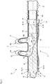
2 eine schematische Längsschnittansicht durch die Ausführungsform von1 , wobei die Schnittebene die Verteilbahn enthält, -
3 eine der Ansicht von2 entsprechende Längsschnittansicht einer zweiten Ausführungsform einer erfindungsgemäßen Nasenbrille mit einen von der Nasenbrille von2 abweichenden Stopfen, -
4 eine den Ansichten der2 und3 entsprechende weitere Längsschnittansicht durch eine dritte erfindungsgemäße Ausführungsform einer Nasenbrille mit einem noch weiteren verschiedenen Stopfen und -
5 eine teilgeschnittene perspektivische Ansicht des Verteilbauteils mit einer Unteransicht des Stopfens der ersten Ausführungsform.
-
1 2 shows a schematic exploded view of a first embodiment of nasal cannula according to the invention, -
2nd is a schematic longitudinal sectional view through the embodiment of1 , where the cutting plane contains the distribution path, -
3rd one of the view from2nd corresponding longitudinal sectional view of a second embodiment of a nasal cannula according to the invention with one of the nasal cannula of2nd different plugs, -
4th a the views of2nd and3rd corresponding further longitudinal sectional view through a third embodiment of a nasal cannula according to the invention with a further different stopper and -
5 a partially sectioned perspective view of the distribution member with a bottom view of the plug of the first embodiment.
In
Das Verteilkanalbauteil
Das Verteilkanalbauteil
Die Versorgungskanäle
Das Verteilkanalbauteil
In der in
Um einen unerwünschten Austritt von Therapiegas aus dem Verteilkanal
Der bevorzugt einstückig ausgebildete, durch Spritzgießen hergestellte Stopfen
Auf der dem Griffansatz
An die Rastnut
Die Strömungsleitfläche
Die Strömungsleitfläche
Der Stopfen
Der Anschlussstutzen
Zwischen den Abschnitten
In
Die Schnittebene des Längsschnitts durch die Nasenbrille
Wie außerdem in
Der konkave Abschnitt
Die Strömungsleitfläche
Wie aus
Die in
Der Radialvorsprung
Der Formschlusseingriff zwischen Orientierungsformation
Wegen der spiegelsymmetrischen Ausbildung weist das Verteilkanalbauteil
Das Verteilkanalbauteil
In
Gleiche und funktionsgleiche Bauteile wie in der ersten Ausführungsform der
Die zweite Ausführungsform von
Das Verteilkanalbauteil
Zum einen ist in der zweiten Ausführungsform die Strömungsleitfläche
Zugleich ist die Strömungsleitfläche
Ein weiterer markanter Unterschied des Stopfens
Die zweite Strömungsleitfläche
Die zweite Strömungsleitformation
Durch die zweite Strömungsleitformation
Durch die vorgesehenen Strömungsleitflächen
Durch unterschiedlich ausgebildete Stopfen
Die
Gleiche und funktionsgleiche Bauteile und Bauteilabschnitte wie in der ersten Ausführungsform sind in der zweiten Ausführungsform mit gleichen Bezugszeichen versehen, jedoch erhöht um die Zahl
Die dritte Ausführungsform der
Wiederum sind das Verteilkanalbauteil
Der Stopfen
Allerdings ist die Strömungsleitfläche
Mit der in
Es ist ohne weiteres vorstellbar, dass auch der Stopfen
Weiterhin kann daran gedacht sein, verschieden große Therapiegas-Massenströme durch die Abzweigöffnungen dadurch zu erzeugen, dass die Durchströmöffnung (siehe Durchströmöffnung
Auch diese Maßnahmen: unterschiedlich große Durchströmöffnung und Sperrabschnitt
An den Einführlängsenden
In
Eine Nasenbrille
ZITATE ENTHALTEN IN DER BESCHREIBUNG QUOTES INCLUDE IN THE DESCRIPTION
Diese Liste der vom Anmelder aufgeführten Dokumente wurde automatisiert erzeugt und ist ausschließlich zur besseren Information des Lesers aufgenommen. Die Liste ist nicht Bestandteil der deutschen Patent- bzw. Gebrauchsmusteranmeldung. Das DPMA übernimmt keinerlei Haftung für etwaige Fehler oder Auslassungen.This list of documents listed by the applicant has been generated automatically and is only included for the better information of the reader. The list is not part of the German patent or utility model application. The DPMA assumes no liability for any errors or omissions.
Zitierte PatentliteraturPatent literature cited
- US 3754552 A [0002]US 3754552 A [0002]
Claims (17)
Priority Applications (6)
| Application Number | Priority Date | Filing Date | Title |
|---|---|---|---|
| DE102018122516.4A DE102018122516A1 (en) | 2018-09-14 | 2018-09-14 | Nasal cannula with improved, also asymmetrical flow guidance |
| PCT/EP2019/074124 WO2020053220A1 (en) | 2018-09-14 | 2019-09-10 | Nasal cannula having improved and asymmetrical flow control |
| EP19769418.5A EP3849642B1 (en) | 2018-09-14 | 2019-09-10 | Nasal cannula having improved and asymmetrical flow control |
| JP2021513950A JP7357671B2 (en) | 2018-09-14 | 2019-09-10 | Nasal cannula with improved asymmetric flow guidance |
| US17/273,495 US11666723B2 (en) | 2018-09-14 | 2019-09-10 | Nasal cannula having improved and asymmetrical flow control |
| CN201980060284.4A CN112689524A (en) | 2018-09-14 | 2019-09-10 | Nasal cannula with improved asymmetric flow guidance |
Applications Claiming Priority (1)
| Application Number | Priority Date | Filing Date | Title |
|---|---|---|---|
| DE102018122516.4A DE102018122516A1 (en) | 2018-09-14 | 2018-09-14 | Nasal cannula with improved, also asymmetrical flow guidance |
Publications (1)
| Publication Number | Publication Date |
|---|---|
| DE102018122516A1 true DE102018122516A1 (en) | 2020-03-19 |
Family
ID=67982039
Family Applications (1)
| Application Number | Title | Priority Date | Filing Date |
|---|---|---|---|
| DE102018122516.4A Withdrawn DE102018122516A1 (en) | 2018-09-14 | 2018-09-14 | Nasal cannula with improved, also asymmetrical flow guidance |
Country Status (6)
| Country | Link |
|---|---|
| US (1) | US11666723B2 (en) |
| EP (1) | EP3849642B1 (en) |
| JP (1) | JP7357671B2 (en) |
| CN (1) | CN112689524A (en) |
| DE (1) | DE102018122516A1 (en) |
| WO (1) | WO2020053220A1 (en) |
Cited By (1)
| Publication number | Priority date | Publication date | Assignee | Title |
|---|---|---|---|---|
| WO2020245323A1 (en) | 2019-06-07 | 2020-12-10 | Hamilton Medical Ag | Nasal cannula with a better-secured connection to a supply line |
Families Citing this family (10)
| Publication number | Priority date | Publication date | Assignee | Title |
|---|---|---|---|---|
| SG10201909092SA (en) | 2015-03-31 | 2019-11-28 | Fisher & Paykel Healthcare Ltd | A user interface and system for supplying gases to an airway |
| USD825053S1 (en) * | 2016-03-23 | 2018-08-07 | Fisher & Paykel Healthcare Limited | Nasal cannula |
| GB2607540B (en) * | 2016-08-11 | 2023-03-29 | Fisher & Paykel Healthcare Ltd | A collapsible conduit, patient interface and headgear connector |
| US11666722B2 (en) | 2020-03-04 | 2023-06-06 | 3B Medical, Inc. | Nasal cannula without nostril prongs |
| CN213554576U (en) * | 2020-10-14 | 2021-06-29 | 沈阳迈思医疗科技有限公司 | Oxygen inhalation nasal plug device |
| AU2021221439A1 (en) * | 2020-12-23 | 2022-07-07 | Fisher & Paykel Healthcare Limited | Tube and/or patient interface for delivery of gas |
| USD1101928S1 (en) * | 2021-09-07 | 2025-11-11 | Fisher & Paykel Healthcare Limited | Nasal cannula for a nasal interface |
| JP2024539197A (en) * | 2021-10-22 | 2024-10-28 | フィッシャー アンド ペイケル ヘルスケア リミテッド | Patient Interface |
| USD1104244S1 (en) * | 2022-04-14 | 2025-12-02 | Fisher & Paykel Healthcare Limited | Mask cushion for a patient interface |
| EP4669396A1 (en) * | 2023-02-24 | 2025-12-31 | Fisher & Paykel Healthcare Limited | PATIENT INTERFACE |
Citations (2)
| Publication number | Priority date | Publication date | Assignee | Title |
|---|---|---|---|---|
| DE202014100110U1 (en) * | 2013-09-30 | 2014-01-30 | Great Group Medical Co., Ltd. | Oxygenated nasal cannula, whose connection points for a sealing plug and an oxygen connection are interchangeable |
| US20160271353A1 (en) * | 2012-12-11 | 2016-09-22 | Koninklijke Philips N.V. | Nasal cannula system and method |
Family Cites Families (11)
| Publication number | Priority date | Publication date | Assignee | Title |
|---|---|---|---|---|
| US3754552A (en) * | 1971-06-08 | 1973-08-28 | Sandoz Ag | Flexible nasal cannula |
| US5451349A (en) * | 1994-08-08 | 1995-09-19 | Praxair Technology, Inc. | Advanced gas control in gas-liquid mixing systems |
| DE202004021759U1 (en) * | 2003-02-21 | 2010-10-07 | ResMed Ltd., Bella Vista | Nasal arrangement |
| AU2004202274B2 (en) | 2003-05-30 | 2006-10-26 | Fisher & Paykel Healthcare Limited | Breathing Assistance Apparatus |
| JP4261379B2 (en) * | 2004-02-05 | 2009-04-30 | 株式会社荏原製作所 | Silencer |
| CN101683546A (en) * | 2004-04-09 | 2010-03-31 | 雷斯梅德有限公司 | Nasal assembly |
| US7966831B2 (en) * | 2007-08-28 | 2011-06-28 | General Electric Company | Apparatus and method for suppressing dynamic pressure instability in bleed duct |
| DE112009000517T5 (en) | 2008-03-04 | 2011-02-03 | ResMed Ltd., Bella Vista | Unobtrusive coupling systems |
| CA2894279A1 (en) | 2012-12-07 | 2014-06-12 | Paul Boucher | Nasal cannula for delivery of aerosolized medicaments |
| EP4275731A3 (en) | 2013-03-15 | 2023-12-27 | Fisher & Paykel Healthcare Limited | Nasal cannula assemblies |
| CN206139357U (en) * | 2016-10-21 | 2017-05-03 | 罗力 | Tangential entry separates assembly and uses contrajet cyclone of this separation assembly |
-
2018
- 2018-09-14 DE DE102018122516.4A patent/DE102018122516A1/en not_active Withdrawn
-
2019
- 2019-09-10 CN CN201980060284.4A patent/CN112689524A/en active Pending
- 2019-09-10 EP EP19769418.5A patent/EP3849642B1/en active Active
- 2019-09-10 WO PCT/EP2019/074124 patent/WO2020053220A1/en not_active Ceased
- 2019-09-10 JP JP2021513950A patent/JP7357671B2/en active Active
- 2019-09-10 US US17/273,495 patent/US11666723B2/en active Active
Patent Citations (2)
| Publication number | Priority date | Publication date | Assignee | Title |
|---|---|---|---|---|
| US20160271353A1 (en) * | 2012-12-11 | 2016-09-22 | Koninklijke Philips N.V. | Nasal cannula system and method |
| DE202014100110U1 (en) * | 2013-09-30 | 2014-01-30 | Great Group Medical Co., Ltd. | Oxygenated nasal cannula, whose connection points for a sealing plug and an oxygen connection are interchangeable |
Cited By (1)
| Publication number | Priority date | Publication date | Assignee | Title |
|---|---|---|---|---|
| WO2020245323A1 (en) | 2019-06-07 | 2020-12-10 | Hamilton Medical Ag | Nasal cannula with a better-secured connection to a supply line |
Also Published As
| Publication number | Publication date |
|---|---|
| JP2022500149A (en) | 2022-01-04 |
| WO2020053220A1 (en) | 2020-03-19 |
| CN112689524A (en) | 2021-04-20 |
| US11666723B2 (en) | 2023-06-06 |
| JP7357671B2 (en) | 2023-10-06 |
| EP3849642A1 (en) | 2021-07-21 |
| US20210338960A1 (en) | 2021-11-04 |
| EP3849642B1 (en) | 2022-10-26 |
Similar Documents
| Publication | Publication Date | Title |
|---|---|---|
| EP3849642B1 (en) | Nasal cannula having improved and asymmetrical flow control | |
| DE69327158T2 (en) | CATHETER WITH ATRAUMATIC TIP FOR THE ADMINISTRATION OF MEDICINAL PRODUCTS | |
| DE69431257T2 (en) | INFUSION CATHETER WITH EVEN DISPENSING OF LIQUIDS | |
| DE69631779T2 (en) | CATHETERS, ESPECIALLY FOR PERITONEAL DIALYSIS | |
| DE69724349T2 (en) | Syringe plunger | |
| EP1256358B1 (en) | Infusion set for drug delivery | |
| EP2854920B1 (en) | Laryngeal mask with supraglottic tube | |
| DE9290177U1 (en) | Improved valve catheter | |
| DE10121356B4 (en) | Valve arrangement for surgical instruments and valve basket for receiving the valve arrangement | |
| EP1592473B1 (en) | Aortic cannula | |
| EP3799563B1 (en) | Spray head for a device for producing a stream of air in the outer ear | |
| EP3624883A1 (en) | Exhalation valve for a ventilator apparatus with noise-reducing flow resistance | |
| DE19619065C2 (en) | Trocar sleeve with a valve | |
| DE60038385T2 (en) | SUCTION CONNECTOR AND THUS PROVIDED CATHETER | |
| DE102013222042A1 (en) | Deflection movement transmission device, endoscope deflecting control and endoscope | |
| WO2008135475A1 (en) | Molded pipe part for infusion devices | |
| EP2195075B1 (en) | Device for administering medical liquids | |
| DE602004000626T2 (en) | Medical delivery device for low fluid flow rate fluids | |
| DE4210984C2 (en) | Trocar for minimally invasive surgery | |
| EP4169544B1 (en) | Attachment for a device for generating an air flow or for delivering a fluid into the external auditory canal | |
| DE4141154C2 (en) | Arrangement with a ureteral splint, an auxiliary splint, and a stylet | |
| DE202019104935U1 (en) | Flow regulator | |
| DE2905626A1 (en) | DRAINAGE DEVICE FOR DRAWING OFF LIQUIDS, IN PARTICULAR FOR MEDICAL PURPOSES | |
| DE102008026237A1 (en) | Intracerebral injection instrument | |
| DE102013018458A1 (en) | Y-piece for ventilation system, Y-branch kit, method and apparatus for making same |
Legal Events
| Date | Code | Title | Description |
|---|---|---|---|
| R163 | Identified publications notified | ||
| R119 | Application deemed withdrawn, or ip right lapsed, due to non-payment of renewal fee |