DE102018102768B4 - System with a workpiece in the form of a threaded spindle and with a fine machining device - Google Patents
System with a workpiece in the form of a threaded spindle and with a fine machining device Download PDFInfo
- Publication number
- DE102018102768B4 DE102018102768B4 DE102018102768.0A DE102018102768A DE102018102768B4 DE 102018102768 B4 DE102018102768 B4 DE 102018102768B4 DE 102018102768 A DE102018102768 A DE 102018102768A DE 102018102768 B4 DE102018102768 B4 DE 102018102768B4
- Authority
- DE
- Germany
- Prior art keywords
- axis
- pressing
- workpiece
- abrasive
- pressure element
- Prior art date
- Legal status (The legal status is an assumption and is not a legal conclusion. Google has not performed a legal analysis and makes no representation as to the accuracy of the status listed.)
- Active
Links
- 238000003754 machining Methods 0.000 title claims abstract description 23
- 238000003825 pressing Methods 0.000 claims abstract description 42
- 230000010355 oscillation Effects 0.000 claims description 5
- 238000006073 displacement reaction Methods 0.000 claims 1
- 238000000034 method Methods 0.000 description 4
- 238000005498 polishing Methods 0.000 description 3
- 238000007730 finishing process Methods 0.000 description 2
- 238000005096 rolling process Methods 0.000 description 2
- 238000005520 cutting process Methods 0.000 description 1
- 238000007517 polishing process Methods 0.000 description 1
- 230000001360 synchronised effect Effects 0.000 description 1
- 239000011800 void material Substances 0.000 description 1
Images


Classifications
-
- B—PERFORMING OPERATIONS; TRANSPORTING
- B23—MACHINE TOOLS; METAL-WORKING NOT OTHERWISE PROVIDED FOR
- B23G—THREAD CUTTING; WORKING OF SCREWS, BOLT HEADS, OR NUTS, IN CONJUNCTION THEREWITH
- B23G1/00—Thread cutting; Automatic machines specially designed therefor
- B23G1/36—Thread cutting; Automatic machines specially designed therefor by grinding
-
- B—PERFORMING OPERATIONS; TRANSPORTING
- B24—GRINDING; POLISHING
- B24B—MACHINES, DEVICES, OR PROCESSES FOR GRINDING OR POLISHING; DRESSING OR CONDITIONING OF ABRADING SURFACES; FEEDING OF GRINDING, POLISHING, OR LAPPING AGENTS
- B24B53/00—Devices or means for dressing or conditioning abrasive surfaces
- B24B53/06—Devices or means for dressing or conditioning abrasive surfaces of profiled abrasive wheels
- B24B53/075—Devices or means for dressing or conditioning abrasive surfaces of profiled abrasive wheels for workpieces having a grooved profile, e.g. gears, splined shafts, threads, worms
Landscapes
- Engineering & Computer Science (AREA)
- Mechanical Engineering (AREA)
- Finish Polishing, Edge Sharpening, And Grinding By Specific Grinding Devices (AREA)
Abstract
System (10), mit einem Werkstück (12) in Form einer Gewindespindel (14) und mit einer Feinbearbeitungsvorrichtung (20) zur Bearbeitung der Gewindespindel (14), wobei die Feinbearbeitungsvorrichtung (20) ein abrasiv wirkendes Feinbearbeitungswerkzeug in Form eines Abrasivbandes (22) aufweist, ferner ein Andrückelement (44) zum Andrücken des Abrasivbandes (22) gegen einen Gewindeabschnitt (68) der Gewindespindel (14), wobei das Andrückelement (44) einen Andrückabschnitt (62) aufweist, der unter Zwischenlage des Abrasivbandes (22) in einen Arbeitsraum (74) einbringbar ist, der von zwei zueinander benachbarten, einander zugewandten Gewindeflanken (70, 72) begrenzt ist, dadurch gekennzeichnet, dass in einer Grundstellung des Andrückelements (44) der Andrückabschnitt (62) und das Abrasivband (22) mit Spiel behaftet in dem Arbeitsraum (74) anordenbar sind, dass ein Schwenkantrieb (38) vorgesehen ist, mittels welchem das Andrückelement (44) um eine Schwenkachse (42) verschwenkbar ist, wobei in einer relativ zu der Grundstellung verschwenkten Arbeitsstellung des Andrückelements (44) der Andrückabschnitt (62) mit zwei voneinander abgewandten Andrückflächen (64, 66) unterschiedliche Abschnitte (22a, 22b) des Abrasivbandes (22) gegen die einander zugewandten Gewindeflanken (70, 72) drückt.System (10), with a workpiece (12) in the form of a threaded spindle (14) and with a fine machining device (20) for machining the threaded spindle (14), the fine machining device (20) having an abrasive fine machining tool in the form of an abrasive belt (22) comprises, furthermore a pressing element (44) for pressing the abrasive belt (22) against a threaded section (68) of the threaded spindle (14), the pressing element (44) having a pressing section (62) which, with the interposition of the abrasive belt (22) in a Working space (74) can be introduced which is delimited by two mutually adjacent, facing thread flanks (70, 72), characterized in that in a basic position of the pressing element (44) the pressing section (62) and the abrasive band (22) have play can be arranged in the working space (74) that a pivot drive (38) is provided, by means of which the pressure element (44) can be pivoted about a pivot axis (42), wherein in a working position of the pressure element (44) pivoted relative to the basic position, the pressure section (62) with two opposing pressure surfaces (64, 66) presses different sections (22a, 22b) of the abrasive band (22) against the mutually facing thread flanks (70, 72) .
Description
Die Erfindung betrifft ein System gemäß
Aus der
Prinzipiell wäre es möglich, das vorstehende Verfahren auch zur Bearbeitung von Gewindespindeln zu verwenden, welche einen Arbeitsraum zwischen zwei zueinander benachbarten, einander zugewandten Gewindeflanken begrenzen. Die Rohgeometrie einer Gewindespindel entsteht beispielsweise im Rahmen eines Gewindewalz- oder Gewinderollprozess, bei welchen zylindrische Rohlinge so verformt werden, dass eine Gewindestruktur entsteht. Solchermaßen hergestellte Rohgeometrien weisen verfahrensbedingte Unregelmäßigkeiten, also Abweichungen der Geometrie der Gewindeflanken von einer Sollgeometrie, auf. Bei einer Anwendung des in der
Hiervon ausgehend liegt der vorliegenden Erfindung die Aufgabe zugrunde, eine Feinbearbeitungsvorrichtung bereitzustellen, die es ermöglicht, die Gewindeflanken einer Gewindespindel mit einer definierten Oberflächenstruktur zu versehen, wobei vorstehend diskutierte Nachteile vermieden werden sollen.Proceeding from this, the present invention is based on the object of providing a fine machining device which makes it possible to provide the thread flanks of a threaded spindle with a defined surface structure, the disadvantages discussed above being to be avoided.
Diese Aufgabe wird bei einem System der eingangs genannten Art dadurch gelöst, dass in einer Grundstellung des Andrückelements der Andrückabschnitt und das Abrasivband mit Spiel behaftet in dem Arbeitsraum anordenbar sind, dass ein Schwenkantrieb vorgesehen ist, mittels welchem das Andrückelement um eine Schwenkachse verschwenkbar ist, wobei in einer relativ zu der Grundstellung verschwenkten Arbeitsstellung des Andrückelements der Andrückabschnitt mit zwei voneinander abgewandten Andrückflächen unterschiedliche Abschnitte des Abrasivbandes gegen die einander zugewandten Gewindeflanken drückt.This object is achieved in a system of the type mentioned at the outset in that, in a basic position of the pressure element, the pressure section and the abrasive band with play can be arranged in the working space, that a pivot drive is provided by means of which the pressure element can be pivoted about a pivot axis, whereby In a working position of the pressing element pivoted relative to the basic position, the pressing section presses different sections of the abrasive tape with two pressing surfaces facing away from one another against the thread flanks facing one another.
Erfindungsgemäß sind die Abstände der Gewindeflanken einerseits und die Geometrie des Andrückabschnitts des Andrückelements sowie die Dicke des Abrasivbandes andererseits derart aufeinander abgestimmt, dass zumindest in einer Grundstellung des Andrückelements der Andrückabschnitt und das Abrasivband mit Spiel behaftet in dem zwischen den Gewindeflanken begrenzten Arbeitsraum anordenbar sind. Das Andrückelement ist um eine Schwenkachse verschwenkbar, sodass der Andrückabschnitt in einer Arbeitsstellung mit voneinander abgewandten Andrückflächen an den Gewindeflanken der Gewindespindeln anliegt. Es wird also zunächst ein Spiel vorgehalten, dass dann durch das Verschwenken des Andrückelements ausgeglichen wird. Etwaige Veränderungen des Abstands der Gewindeflanken (eingangs beschriebene „Unregelmäßigkeiten“) längs des Verlaufs des Gewindes der Gewindespindel können durch minimale Verschwenkbewegungen des Andrückelements ausgeglichen werden.According to the invention, the distances between the thread flanks on the one hand and the geometry of the pressure section of the pressure element and the thickness of the abrasive tape on the other hand are matched to one another in such a way that at least in a basic position of the pressure element the pressure section and the abrasive band with play can be arranged in the working space delimited between the thread flanks. The pressing element can be pivoted about a pivot axis, so that the pressing section rests against the thread flanks of the threaded spindles in a working position with pressing surfaces facing away from one another. So there is initially a game that is then compensated for by pivoting the pressure element. Any changes in the distance between the thread flanks (“irregularities” described at the beginning) along the course of the thread of the threaded spindle can be compensated for by minimal pivoting movements of the pressure element.
Es ist bevorzugt, dass der Schwenkantrieb kraftgesteuert ist, sodass die Anlage der Andrückflächen an rückseitigen Abschnitten des Abrasivbandes und das Andrücken vorderseitiger abrasiv wirkender Abschnitte des Abrasivbandes an den Gewindeflanken mit einer vorgebbaren Kraft erfolgt. Dadurch ist eine konstante Andrückkraft gewährleistet, wobei gleichzeitig - durch minimale Schwenkbewegungen des Andrückelements - geometrische Unregelmäßigkeiten der Gewindeflanken ausgeglichen werden können.It is preferred that the pivot drive is force-controlled, so that the contact of the pressing surfaces on the rear sections of the abrasive belt and the pressing of the front, abrasive sections of the abrasive belt on the thread flanks take place with a predeterminable force. This ensures a constant pressing force, and at the same time - by minimal pivoting movements of the pressing element - geometric irregularities of the thread flanks can be compensated for.
Es ist bevorzugt, dass das Andrückelement in seiner Grundstellung bezogen auf die zwei einander zugewandten Gewindeflanken symmetrisch ausgerichtet ist, um in der Grundstellung ein jeweiliges Spiel zu beiden Gewindeflanken vorzuhalten.It is preferred that the pressure element is aligned symmetrically in its basic position with respect to the two mutually facing thread flanks, in order to maintain a respective play in relation to both thread flanks in the basic position.
Vorzugsweise verläuft die Schwenkachse senkrecht zu der Werkstückachse. Dies vereinfacht die Definition der Grundstellung und ermöglicht es, einen im Profil symmetrischen Andrückabschnitt zu verwenden.The pivot axis preferably runs perpendicular to the workpiece axis. This simplifies the definition of the basic position and makes it possible to use a pressure section that is symmetrical in profile.
Vorzugsweise schneidet die Schwenkachse die Werkstückachse. Dies ermöglicht es, den Verlauf und die Länge der jeweiligen Kontaktbereiche der Andrückflächen optimal zu verteilen, sodass die beiden Kontaktbereiche vorzugsweise hinsichtlich ihrer Länge und ihres Verlaufs zueinander symmetrisch sind.The pivot axis preferably intersects the workpiece axis. This makes it possible to optimally distribute the course and the length of the respective contact areas of the pressing surfaces, so that the two contact areas are preferably symmetrical to one another with regard to their length and course.
Ferner ist es bevorzugt, dass ein Rotationsantrieb zur Rotation des Werkstücks um die Werkstückachse vorgesehen ist. Dies ist eine einfache Möglichkeit, hohe Schnittgeschwindigkeiten bereitzustellen.Furthermore, it is preferred that a rotary drive is provided for rotating the workpiece about the workpiece axis. This is an easy way to provide high cutting speeds.
Vorzugsweise ist das Andrückelement in Form einer Andrückscheibe ausgebildet. Eine solche Scheibe ermöglicht die Bereitstellung eines Andrückabschnitts in Form eines endlos umlaufenden Andrückabschnitts.The pressure element is preferably designed in the form of a pressure disk. Such a disk enables the provision of a pressing section in the form of an endlessly rotating pressing section.
Es ist bevorzugt, dass das Andrückelement um eine Drehachse verdrehbar ist. Dies ermöglicht es, einen Andrückabschnitt durch einfaches Drehen des Andrückelements nachführen zu können, wobei die Geschwindigkeit des Andrückabschnitts vorzugsweise mit einer Vorschubgeschwindigkeit des Abrasivbandes korrespondiert.It is preferred that the pressure element can be rotated about an axis of rotation. This makes it possible to be able to track a pressing section by simply rotating the pressing element, the speed of the pressing section preferably corresponding to a feed rate of the abrasive belt.
Vorzugsweise verläuft die Drehachse des Andrückelements in der Grundstellung des Andrückelements zu der Werkstückachse parallel. Auf diese Weise kann ein bezogen auf den Arbeitsraum vergleichsweise großer Andrückabschnitt bereitgestellt werden.The axis of rotation of the pressing element preferably runs parallel to the workpiece axis in the basic position of the pressing element. In this way, a pressing section which is comparatively large in relation to the working space can be provided.
Vorzugsweise ist die Drehachse von einem Drehlager gebildet ist, das mittels des Schwenkantriebs verschwenkbar ist. Dies ermöglich es, ein um die Drehachse drehbares Andrückelement zu verschwenken.The axis of rotation is preferably formed by a pivot bearing which can be pivoted by means of the pivot drive. This makes it possible to pivot a pressure element that can rotate about the axis of rotation.
Bevorzugt ist es, wenn das Andrückelement längs der Drehachse in axialer Richtung längs eines begrenzten Axialwegs bewegbar ist. Hierdurch wird eine weitere Ausgleichsmöglichkeit zur Kompensation von Unregelmäßigkeiten der Gewindeflanken geschaffen. Außerdem ist es somit möglich, dass eine Umdrehungsbewegung der Gewindespindel, eine Steigung des Gewindes einerseits und eine Relativbewegung des Abrasivbandes in einer zu der Werkstückachse parallelen Richtung nicht perfekt zueinander synchronisiert werden müssen.It is preferred if the pressure element can be moved along the axis of rotation in the axial direction along a limited axial path. This creates a further compensation option for compensating for irregularities in the thread flanks. In addition, it is thus possible that a rotational movement of the threaded spindle, a pitch of the thread on the one hand and a relative movement of the abrasive belt in a direction parallel to the workpiece axis do not have to be perfectly synchronized with one another.
Ferner ist es bevorzugt, wenn eine Feststelleinrichtung vorgesehen ist, mittels welcher eine Position des Andrückelements längs der Drehachse in axialer Richtung lösbar feststellbar ist. Dies hat den Vorteil, dass eine Position des Andrückelements längs der Drehachse festlegbar ist, sodass der Andrückabschnitt von außen her kollisionsfrei in den Arbeitsraum eingebracht werden kann. Während der Feinbearbeitung kann die Feststelleinrichtung gelöst werden, sodass die vorstehend beschriebene, weitere Ausgleichsmöglichkeit realisiert wird.Furthermore, it is preferred if a locking device is provided by means of which a position of the pressure element along the axis of rotation can be releasably locked in the axial direction. This has the advantage that a position of the pressure element can be fixed along the axis of rotation, so that the pressure section can be introduced into the working space from the outside without collision. During the fine machining, the locking device can be released so that the further compensation option described above is realized.
Vorzugsweise ist eine Bandfördereinrichtung vorgesehen, mittels welcher das Abrasivband zumindest in einer Vorschubrichtung förderbar ist. Besonders bevorzugt ist ein kontinuierlicher Bandvorschub, wodurch eine aufwändige Indexierung vermieden wird und gleichzeitig gewährleistet ist, dass entlang des Verlaufs des Gewindes der Gewindespindel kontinuierlich frisches Abrasivband zur Verfügung gestellt werden kann.A belt conveyor device is preferably provided, by means of which the abrasive belt can be conveyed at least in one feed direction. A continuous tape feed is particularly preferred, as a result of which complex indexing is avoided and at the same time it is ensured that fresh abrasive tape can be continuously made available along the course of the thread of the threaded spindle.
Es ist möglich, dass die Bandfördereinrichtung auch in einer Rückschubrichtung fördert, sodass das Abrasivband „sägeartig“ hin- und herbewegt wird, wodurch eine zusätzliche Bewegungskomponente erzeugt wird, ähnlich einer Oszillationsbewegung bei einem Finishverfahren.It is possible that the belt conveyor device also conveys in a reverse feed direction, so that the abrasive belt is moved back and forth in a “saw-like manner”, whereby an additional movement component is generated, similar to an oscillating movement in a finishing process.
Vorzugsweise ist eine Positioniereinrichtung vorgesehen, mittels welcher das Andrückelement, vorzugsweise auch der Schwenkantrieb, in einer zu der Schwenkachse parallelen Richtung und/oder in einer bezogen auf die Werkstückachse radialer Richtung positionierbar ist. Dies ermöglicht eine automatisierte Einbringung des Andrückabschnitts in den Arbeitsraum.A positioning device is preferably provided, by means of which the pressure element, preferably also the pivot drive, can be positioned in a direction parallel to the pivot axis and / or in a radial direction with respect to the workpiece axis. This enables an automated introduction of the pressing section into the work space.
Vorzugsweise ist eine Verfahreinrichtung vorgesehen, mittels welcher das Andrückelement, vorzugsweise auch der Schwenkantrieb, in einer zu der Werkstückachse parallelen Richtung verfahrbar ist, vorzugsweise entlang der gesamten Länge des Werkstücks. Hierdurch ist es möglich, dass die Gesamtlänge des Systems nicht länger oder nicht wesentlich länger als die Länge des Werkstücks sein muss.A moving device is preferably provided by means of which the pressure element, preferably also the pivot drive, can be moved in a direction parallel to the workpiece axis, preferably along the entire length of the workpiece. This makes it possible that the total length of the system does not have to be longer or not significantly longer than the length of the workpiece.
Ferner ist es möglich, dass eine Oszillationseinrichtung vorgesehen ist, mittels welcher eine Relativbewegung zwischen Werkstück und Abrasivband erzeugbar ist, die bezogen auf die Werkstückachse in tangentialer Richtung verläuft. Hierdurch lässt sich eine Finishbearbeitung realisieren, welche durch eine Überlagerung von Rotationsbewegung des Werkstücks relativ zu dem Werkzeug (hier: Abrasivband) und einer Oszillationsbewegung des Werkzeugs relativ zu dem Werkstück charakterisiert ist.Furthermore, it is possible that an oscillation device is provided, by means of which a relative movement can be generated between the workpiece and the abrasive band, which movement runs in a tangential direction with respect to the workpiece axis. In this way, a finishing process can be implemented which is characterized by a superposition of rotational movement of the workpiece relative to the tool (here: abrasive tape) and an oscillating movement of the tool relative to the workpiece.
Die Erfindung betrifft auch ein Feinbearbeitungsvorrichtung zur Verwendung bei einem vorstehend beschriebenen System.The invention also relates to a finishing device for use in a system as described above.
Weitere Merkmale und Vorteile der Erfindung sind Gegenstand der nachfolgenden Beschreibung und der zeichnerischen Darstellung eines bevorzugten Ausführungsbeispiels.Further features and advantages of the invention are the subject matter of the following description and the graphic representation of a preferred exemplary embodiment.
In der Zeichnung zeigt
-
1 eine perspektivische Ansicht einer Ausführungsform eines Systems mit einer Feinbearbeitungsvorrichtung und mit einer Gewindespindel; -
2 eine Draufsicht eines Teils eines Andrückelements der Feinbearbeitungsvorrichtung und der Gewindespindel gemäß1 , wobei das Andrückelement in seiner Grundstellung dargestellt ist; -
3 eine der2 entsprechende Ansicht, mit schematischer Darstellung eines Abrasivbandes; -
4 eine Schnittansicht längs einer in3 mit IV-IV bezeichneten Schnittebene; -
5 eine der2 entsprechende Ansicht, wobei das Andrückelement in einer aus seiner Grundstellung verschwenkten Arbeitsstellung dargestellt ist; -
6 eine perspektivische Ansicht des Systems in der Arbeitsstellung des Andrückelements; -
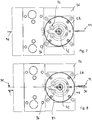
7 eine Rückansicht der Feinbearbeitungsvorrichtung in der Grundstellung des Andrückelements; -
8 eine der7 entsprechende Ansicht in der Arbeitsstellung des Andrückelements; und -
9 eine Seitenansicht einer weiteren Ausführungsform eines Systems mit einer Feinbearbeitungsvorrichtung und mit einer Gewindespindel, wobei die Feinbearbeitungsvorrichtung eine Oszillationseinrichtung aufweist.
-
1 a perspective view of an embodiment of a system with a fine machining device and with a threaded spindle; -
2 a plan view of a part of a pressure element of the fine machining device and the threaded spindle according to FIG1 , wherein the pressure element is shown in its basic position; -
3 one of the2 corresponding view, with a schematic representation of an abrasive belt; -
4th a sectional view along an in3 section plane designated IV-IV; -
5 one of the2 Corresponding view, the pressure element being shown in a working position pivoted from its basic position; -
6th a perspective view of the system in the working position of the pressure element; -
7th a rear view of the fine machining device in the basic position of the pressure element; -
8th one of the7th corresponding view in the working position of the pressure element; and -
9 a side view of a further embodiment of a system with a fine machining device and with a threaded spindle, the fine machining device having an oscillation device.
Ein in der Zeichnung dargestelltes System
Das System umfasst ferner eine insgesamt mit dem Bezugszeichen
Die Feinbearbeitungsvorrichtung
Die Feinbearbeitungsvorrichtung
An dem Gestellteil
An dem Schwenkträger
Längs der Drehachse
Die Andrückscheibe
Die Gewindespindel weist einen Gewindeabschnitt
In
Ein Verschwenken der Andrückscheibe in eine Arbeitsstellung bewirkt eine Bewegung der Andrückflächen
Zur Definition der Schwenklagen ist es bevorzugt, dass Endlagen des Schwenkträgers
Die Besonderheit der in
Claims (14)
Priority Applications (1)
| Application Number | Priority Date | Filing Date | Title |
|---|---|---|---|
| DE102018102768.0A DE102018102768B4 (en) | 2018-02-07 | 2018-02-07 | System with a workpiece in the form of a threaded spindle and with a fine machining device |
Applications Claiming Priority (1)
| Application Number | Priority Date | Filing Date | Title |
|---|---|---|---|
| DE102018102768.0A DE102018102768B4 (en) | 2018-02-07 | 2018-02-07 | System with a workpiece in the form of a threaded spindle and with a fine machining device |
Publications (2)
| Publication Number | Publication Date |
|---|---|
| DE102018102768A1 DE102018102768A1 (en) | 2019-08-08 |
| DE102018102768B4 true DE102018102768B4 (en) | 2021-10-14 |
Family
ID=67308790
Family Applications (1)
| Application Number | Title | Priority Date | Filing Date |
|---|---|---|---|
| DE102018102768.0A Active DE102018102768B4 (en) | 2018-02-07 | 2018-02-07 | System with a workpiece in the form of a threaded spindle and with a fine machining device |
Country Status (1)
| Country | Link |
|---|---|
| DE (1) | DE102018102768B4 (en) |
Families Citing this family (2)
| Publication number | Priority date | Publication date | Assignee | Title |
|---|---|---|---|---|
| CN112643150A (en) * | 2019-10-10 | 2021-04-13 | 安志飞 | Semi-automatic thread grinding device for lathe |
| CN111152134B (en) * | 2020-01-21 | 2025-02-07 | 科德数控股份有限公司 | Grinding wheel dresser |
Citations (1)
| Publication number | Priority date | Publication date | Assignee | Title |
|---|---|---|---|---|
| DE102014111790A1 (en) | 2013-08-20 | 2015-02-26 | I.D.O. Co., Ltd. | A method of polishing a ball screw and ball screw polishing jig |
-
2018
- 2018-02-07 DE DE102018102768.0A patent/DE102018102768B4/en active Active
Patent Citations (2)
| Publication number | Priority date | Publication date | Assignee | Title |
|---|---|---|---|---|
| DE102014111790A1 (en) | 2013-08-20 | 2015-02-26 | I.D.O. Co., Ltd. | A method of polishing a ball screw and ball screw polishing jig |
| JP2015061734A (en) | 2013-08-20 | 2015-04-02 | 株式会社サンシン | Ball screw polishing method and device thereof |
Also Published As
| Publication number | Publication date |
|---|---|
| DE102018102768A1 (en) | 2019-08-08 |
Similar Documents
| Publication | Publication Date | Title |
|---|---|---|
| EP2353758B2 (en) | Machining tool | |
| DE2856519C2 (en) | Machine for grinding the edges of glass sheets | |
| DE10144649C5 (en) | Method for twist-free machining of rotationally symmetrical surfaces | |
| EP2392438B1 (en) | Processing device | |
| EP2025465B1 (en) | Device for working a metallic workpiece | |
| DE3390141C2 (en) | Device for finishing a screw thread cut into a cylindrical piece by smooth rolling | |
| EP1533078B1 (en) | Devided grinding tool | |
| EP1286794B2 (en) | Cold rolling machine | |
| WO2011063926A1 (en) | Machining station and apparatus for machining a workpiece | |
| EP2636482B1 (en) | Workpiece processing system and method for detailed processing of a workpiece | |
| EP2177664A1 (en) | Method and device for machine cutting a workpiece with a geometrically set blade | |
| DE102018102768B4 (en) | System with a workpiece in the form of a threaded spindle and with a fine machining device | |
| EP2623243A1 (en) | Circular saw blade grinding machine | |
| EP3661684B1 (en) | Hobbing machine, comprising a hobbing slide and a chamfering slide on a common rail system | |
| DE1800871B2 (en) | Honing or grinding device for simultaneous machining of a workpiece with a central bore, two end faces and a characteristic circle (e.g. pitch circle or outer surface), such as a gear wheel or a bearing race | |
| EP2477770B1 (en) | Method of turning a rotating workpiece | |
| EP2794159B1 (en) | Method and milling cutter for machining longitudinal edges of metal workpieces | |
| DE102008047782A1 (en) | Device i.e. rotary swaging machine, for e.g. swaging work piece, has tool jaws arranged coaxial to center axis and divided into tool parts in axial direction, where tool parts are moveable independent of each other | |
| DE2152229A1 (en) | DEBURRING MACHINE FOR BAR MATERIAL BY BRUSHING | |
| DE3913294C2 (en) | Device for milling non-circular profiles | |
| DE202018101202U1 (en) | System, with a workpiece in the form of a threaded spindle and with a finishing device | |
| EP1722912A1 (en) | Method for the production of profiled stips for joint parts | |
| WO2026047129A1 (en) | Device and method for grinding inner contours of workpieces | |
| DE86178C (en) | ||
| EP1479491A1 (en) | Planer |
Legal Events
| Date | Code | Title | Description |
|---|---|---|---|
| R012 | Request for examination validly filed | ||
| R016 | Response to examination communication | ||
| R018 | Grant decision by examination section/examining division | ||
| R020 | Patent grant now final |