DE102011081283A1 - Capacitor with a heat sink - Google Patents

Capacitor with a heat sink Download PDF

Info

Publication number
DE102011081283A1
DE102011081283A1 DE201110081283 DE102011081283A DE102011081283A1 DE 102011081283 A1 DE102011081283 A1 DE 102011081283A1 DE 201110081283 DE201110081283 DE 201110081283 DE 102011081283 A DE102011081283 A DE 102011081283A DE 102011081283 A1 DE102011081283 A1 DE 102011081283A1
Authority
DE
Germany
Prior art keywords
recess
capacitor
housing cup
heat sink
clamping ring
Prior art date
Legal status (The legal status is an assumption and is not a legal conclusion. Google has not performed a legal analysis and makes no representation as to the accuracy of the status listed.)
Withdrawn
Application number
DE201110081283
Other languages
German (de)
Inventor
Zeljko Lubina
Matthias Gesellmann
Markus Wolff
Juergen Minarsch
Current Assignee (The listed assignees may be inaccurate. Google has not performed a legal analysis and makes no representation or warranty as to the accuracy of the list.)
Robert Bosch GmbH
Original Assignee
Robert Bosch GmbH
Priority date (The priority date is an assumption and is not a legal conclusion. Google has not performed a legal analysis and makes no representation as to the accuracy of the date listed.)
Filing date
Publication date
Application filed by Robert Bosch GmbH filed Critical Robert Bosch GmbH
Priority to DE201110081283 priority Critical patent/DE102011081283A1/en
Priority to EP12743426.4A priority patent/EP2745300B1/en
Priority to PCT/EP2012/064543 priority patent/WO2013026645A2/en
Priority to CN201280040526.1A priority patent/CN103748644B/en
Publication of DE102011081283A1 publication Critical patent/DE102011081283A1/en
Withdrawn legal-status Critical Current

Links

Images

Classifications

    • HELECTRICITY
    • H01ELECTRIC ELEMENTS
    • H01GCAPACITORS; CAPACITORS, RECTIFIERS, DETECTORS, SWITCHING DEVICES, LIGHT-SENSITIVE OR TEMPERATURE-SENSITIVE DEVICES OF THE ELECTROLYTIC TYPE
    • H01G2/00Details of capacitors not covered by a single one of groups H01G4/00-H01G11/00
    • H01G2/08Cooling arrangements; Heating arrangements; Ventilating arrangements
    • HELECTRICITY
    • H01ELECTRIC ELEMENTS
    • H01GCAPACITORS; CAPACITORS, RECTIFIERS, DETECTORS, SWITCHING DEVICES, LIGHT-SENSITIVE OR TEMPERATURE-SENSITIVE DEVICES OF THE ELECTROLYTIC TYPE
    • H01G4/00Fixed capacitors; Processes of their manufacture
    • H01G4/002Details
    • H01G4/224Housing; Encapsulation
    • HELECTRICITY
    • H01ELECTRIC ELEMENTS
    • H01GCAPACITORS; CAPACITORS, RECTIFIERS, DETECTORS, SWITCHING DEVICES, LIGHT-SENSITIVE OR TEMPERATURE-SENSITIVE DEVICES OF THE ELECTROLYTIC TYPE
    • H01G4/00Fixed capacitors; Processes of their manufacture
    • H01G4/32Wound capacitors
    • HELECTRICITY
    • H01ELECTRIC ELEMENTS
    • H01GCAPACITORS; CAPACITORS, RECTIFIERS, DETECTORS, SWITCHING DEVICES, LIGHT-SENSITIVE OR TEMPERATURE-SENSITIVE DEVICES OF THE ELECTROLYTIC TYPE
    • H01G4/00Fixed capacitors; Processes of their manufacture
    • H01G4/38Multiple capacitors, i.e. structural combinations of fixed capacitors

Landscapes

  • Engineering & Computer Science (AREA)
  • Power Engineering (AREA)
  • Microelectronics & Electronic Packaging (AREA)
  • Manufacturing & Machinery (AREA)
  • Cooling Or The Like Of Electrical Apparatus (AREA)
  • Table Devices Or Equipment (AREA)

Abstract

Die Erfindung betrifft einen Kondensator, insbesondere Elektrolytkondensator. Der Kondensator weist einen Gehäusebecher auf. Erfindungsgemäß ist der Kondensator mit einem Kühlkörper derart verbunden, dass von dem Kondensator erzeugte Wärme an den Kühlkörper abgegeben werden kann. Der Kühlkörper weist bevorzugt eine Ausnehmung auf, in welcher der Kondensator wenigstens teilweise aufgenommen ist. Der Kondensator, insbesondere der Gehäusebecher, ist in der Ausnehmung mit dem Kühlkörper wenigstens wärmeleitend verbunden.The invention relates to a capacitor, in particular electrolytic capacitor. The capacitor has a housing cup. According to the invention, the condenser is connected to a heat sink such that heat generated by the condenser can be delivered to the heat sink. The heat sink preferably has a recess in which the capacitor is at least partially accommodated. The capacitor, in particular the housing cup, is connected in the recess with the heat sink at least thermally conductive.

Description

Stand der TechnikState of the art

Die Erfindung betrifft einen Kondensator, insbesondere Elektrolytkondensator. Der Kondensator weist einen Gehäusebecher auf. The invention relates to a capacitor, in particular electrolytic capacitor. The capacitor has a housing cup.

Offenbarung der ErfindungDisclosure of the invention

Erfindungsgemäß ist der Kondensator mit einem Kühlkörper derart verbunden, dass von dem Kondensator erzeugte Wärme an den Kühlkörper abgegeben werden kann. Der Kühlkörper weist bevorzugt eine Ausnehmung auf, in welcher der Kondensator wenigstens teilweise, bevorzugt der Gehäusebecher vollständig, aufgenommen ist. Der Kondensator, insbesondere der Gehäusebecher, ist in der Ausnehmung mit dem Kühlkörper wenigstens wärmeleitend verbunden.According to the invention, the condenser is connected to a heat sink such that heat generated by the condenser can be delivered to the heat sink. The heat sink preferably has a recess in which the capacitor is at least partially, preferably the housing cup completely, added. The capacitor, in particular the housing cup, is connected in the recess with the heat sink at least thermally conductive.

Dadurch kann der Kondensator, insbesondere Elektrolytkondensator, vorteilhaft platzsparend in einem Kühlkörper angeordnet sein. Beispielsweise wird der Elektrolytkondensator bei Hochstromanwendungen mit einem als Stanzgitter ausgebildeten Schaltungsträger elektrisch kontaktiert und von dem Schaltungsträger auch mechanisch festgehalten. In einer solchen Ausführungsform kann vorteilhaft ein Teil des Stanzgitters, welcher den Elektrolytkondensator hält, entfallen. As a result, the capacitor, in particular electrolytic capacitor, can advantageously be arranged to save space in a heat sink. For example, in high-current applications, the electrolytic capacitor is electrically contacted with a circuit carrier designed as a stamped grid and also mechanically held by the circuit carrier. In such an embodiment, advantageously a part of the stamped grid holding the electrolytic capacitor can be dispensed with.

Der Kondensator ist in einer anderen Ausführungsform ein Wickelkondensator oder ein Doppelschichtkondensator. Der Doppelschichtkondenstor umfasst bevorzugt wenigstens ein Doppelschicht-Elektrodenpaar, welches weiter bevorzugt zusätzlich als Redox-Elektrodenpaar ausgebildet ist. The capacitor is in another embodiment, a wound capacitor or a double-layer capacitor. The Doppelschichtkondenstor preferably comprises at least one double-layer electrode pair, which is further preferably additionally formed as a redox electrode pair.

Bevorzugt ist der Kühlkörper elektrisch leitfähig ausgebildet, und der Elektrolytkondensator, insbesondere der Gehäusebecher in der Ausnehmung mit dem Kühlkörper elektrisch verbunden. Dadurch kann vorteilhaft ein Teil des Stanzgitters, insbesondere ein Teil, welcher eine elektrische Verbindung zum Kontaktieren eines elektrischen Anschlusses, bevorzugt eines Minuspols des Elektrolytkondensators, entfallen. Weiter vorteilhaft braucht der Elektrolytkondensator an dem Gehäusebecher keinen dort angeschweißten Anschlussdraht zum elektrischen Anschließen eines Pols, insbesondere Minuspols des Elektrolytkondensators aufweisen. In dem Gehäusebecher ist bevorzugt wenigstens eine Elektrode des Kondensators, insbesondere eine Wickelelektrode aufgenommen, welche ausgebildet ist, elektrische Ladungen aufzunehmen, zu speichern und wieder abzugeben. Die Wickelelektrode, im Folgenden auch Wickel genannt, ist von dem Gehäusebecher vor äußeren Einflüssen geschützt umgeben. Preferably, the heat sink is formed electrically conductive, and the electrolytic capacitor, in particular the housing cup in the recess electrically connected to the heat sink. As a result, a part of the stamped grid, in particular a part, which accounts for an electrical connection for contacting an electrical connection, preferably a negative pole of the electrolytic capacitor, can advantageously be dispensed with. Further advantageously, the electrolytic capacitor does not need on the housing cup welded there connecting wire for electrically connecting a pole, in particular negative pole of the electrolytic capacitor. In the housing cup is preferably at least one electrode of the capacitor, in particular a winding electrode accommodated, which is adapted to receive electrical charges, store and deliver again. The winding electrode, also referred to below as winding, is surrounded by the housing cup, protected from external influences.

Der Gehäusebecher weist beispielsweise Aluminium auf, bevorzugt ist der Gehäusebecher aus einer Aluminiumlegierung gebildet. Der Gehäusebecher ist beispielsweise mittels Fließpressen erzeugt. The housing cup has, for example, aluminum, preferably the housing cup is formed from an aluminum alloy. The housing cup is produced for example by means of extrusion.

Der Kühlkörper weist beispielsweise Aluminium auf, bevorzugt ist der Kühlkörper aus einer Aluminiumlegierung gebildet. Der Kühlkörper ist beispielsweise mittels Gießen, insbesondere Druckgießen erzeugt. Die Ausnehmung im Kühlkörper ist beispielsweise gebohrt, gefräst oder beim Gießen ausgeformt. The heat sink, for example, aluminum, preferably, the heat sink is formed of an aluminum alloy. The heat sink is produced for example by means of casting, in particular die casting. The recess in the heat sink is for example drilled, milled or molded during casting.

In einer bevorzugten Ausführungsform ist der Elektrolytkondensator in die Ausnehmung eingepresst. Vorteilhaft ist der Elektrolytkondensator in die Ausnehmung derart eingepresst, dass zwischen wenigstens einem Teil des Gehäusebechers und einer Wand der Ausnehmung des Kühlkörpers eine wärmeleitende, bevorzugt zusätzlich elektrisch leitende Verbindung erzeugt ist.In a preferred embodiment, the electrolytic capacitor is pressed into the recess. Advantageously, the electrolytic capacitor is pressed into the recess such that between at least a part of the housing cup and a wall of the recess of the heat sink, a thermally conductive, preferably additionally electrically conductive connection is produced.

In einer bevorzugten Ausführungsform ist die Ausnehmung wenigstens auf einem Abschnitt nach innen sich verjüngend, insbesondere konisch verlaufend ausgebildet. Dadurch kann der Gehäusebecher vorteilhaft im Bereich der Konizität der Ausnehmung komprimiert werden und so kraftschlüssig festgehalten werden.In a preferred embodiment, the recess is at least on a portion inwardly tapered, in particular conically extending. As a result, the housing cup can advantageously be compressed in the region of the conicity of the recess and thus retained in a force-fitting manner.

In einer bevorzugten Ausführungsform weist der Elektrolytkondensator wenigstens auf einem zum Einpressen ausgebildeten Abschnitt radial abweisende, bevorzugt sich entlang der Längsachse erstreckende Rippen auf, welche ausgebildet sind, den Kühlkörper im Bereich der Ausnehmung wärmeleitend oder zusätzlich elektrisch zu kontaktieren und den Elektrolytkondensator in der Ausnehmung insbesondere federnd festzuklemmen. Die Rippen werden dabei vorteilhaft radial nach innen komprimiert. Bevorzugt ist der Gehäusebecher von Elektroden, insbesondere einem Wickel des Elektrolytkondensators im Innern beabstandet. Bevorzugt ist der Gehäusebecher von dem Wickel des Elektrolytkondensators derart beabstandet, dass beim Komprimieren des zuvor erwähnten Abschnitts, insbesondere Längsabschnitts des Gehäusebechers der Wickel nicht beschädigt werden kann. Durch die Rippen ist vorteilhaft ein zum Komprimieren ausgebildeter Bereich gebildet, wobei die Rippen bevorzugt ausgebildet sind, beim Einpressen des Elektrolytkondensators in die Ausnehmung stärker komprimiert zu werden als eine Wand des Gehäusebechers zu einem eine Elektrode des Kondensators bildenden Wickel hin.In a preferred embodiment, the electrolytic capacitor at least on a section formed for pressing radially deflecting, preferably along the longitudinal axis extending ribs, which are designed to contact the heat sink in the region of the recess thermally conductive or additionally electrically and the electrolytic capacitor in the recess in particular resiliently clamp. The ribs are advantageously compressed radially inwardly. Preferably, the housing cup is spaced from electrodes, in particular a winding of the electrolytic capacitor in the interior. Preferably, the housing cup is spaced from the winding of the electrolytic capacitor such that when compressing the aforementioned portion, in particular longitudinal portion of the housing cup of the winding can not be damaged. The ribs advantageously form a region designed for compression, wherein the ribs are preferably designed to be compressed more strongly during insertion of the electrolytic capacitor into the recess than a wall of the housing cup to form a coil forming an electrode of the capacitor.

Bevorzugt erstreckt sich der Bereich des Gehäusebechers, welcher zum thermischen oder zusätzlich elektrischen Kontaktieren der Ausnehmung ausgebildet ist, zwischen einer ringförmig umlaufenden Nut des Gehäusebechers und einem Boden des Gehäusebechers. Dadurch kann vorteilhaft Wärme aus der ringförmig ausgebildeten Nut, welche im Inneren wenigstens einen Wickel des Elektrolytkondensators berührt, in den Bereich des Gehäusebechers abgeführt werden, welcher mit der Ausnehmung in thermisch leitender Wirkverbindung steht.Preferably, the region of the housing cup, which is designed for the thermal or additionally electrical contacting of the recess, extends between an annular peripheral groove of the housing cup and a bottom of the housing cup. This can be beneficial heat from the ring-shaped groove which contacts at least one winding of the electrolytic capacitor in the interior, are discharged into the region of the housing cup, which is in thermally conductive operative connection with the recess.

Unabhängig oder zusätzlich zu dem zuvor erwähnten am Gehäusebecher des Elektrolytkondensators ausgebildeten Rippen kann der Kühlkörper in der Ausnehmung ausgeformte, sich bevorzugt längserstreckende Rippen aufweisen, wobei die Rippen ausgebildet sind, den Gehäusebecher kraftschlüssig, insbesondere klemmend und zusätzlich federnd festzuhalten. Dadurch kann vorteilhaft ein Flächenbereich des Gehäusebechers mittels der Rippen leicht eingedrückt werden, wobei die Rippen bevorzugt ausgebildet sind, beim Einpressen des Gehäusebechers des Elektrolytkondensators Verschmutzung oder zusätzlich eine Oxidschicht zu durchschaben und den Elektrolytkondensator, insbesondere den Gehäusebecher des Elektrolytkondensators sicher elektrisch kontaktieren. Die Rippen weisen bevorzugt wenigstens eine sich längserstreckende Schneide auf, welche ausgebildet ist, in den Gehäusebecher des Elektrolytkondensators beim Einpressen des Gehäusebechers einzuschneiden und den Gehäusebecher dort sicher elektrisch zu kontaktieren.Independently of or in addition to the abovementioned ribs formed on the housing cup of the electrolytic capacitor, the heat sink may have ribs which are formed in the recess and preferably have longitudinal extension, wherein the ribs are designed to frictionally hold the housing cup, in particular by clamping and additionally resiliently. As a result, advantageously, a surface area of the housing cup can be pressed in slightly by means of the ribs, wherein the ribs are preferably designed to scrape contamination or additionally an oxide layer when the housing cup of the electrolytic capacitor is pressed in and reliably electrically contact the electrolytic capacitor, in particular the housing cup of the electrolytic capacitor. The ribs preferably have at least one longitudinally extending cutting edge which is designed to cut into the housing cup of the electrolytic capacitor when the housing cup is pressed in and securely contact the housing cup electrically there.

In einer anderen vorteilhaften Ausführungsform weist der Gehäusebecher ein Gewinde auf, so dass der Elektrolytkondensator in die Aussparung eingeschraubt werden kann. Dadurch ist der Gehäusebecher formschlüssig in der Aussparung gesichert. Zusätzlich ist ein guter elektrischer Kontakt im Bereich des Gewindes hergestellt, da von dem Gewinde eine Oxidschicht am Gewinde selbst oder zusätzlich in der Aussparung beim Einschrauben durchbrochen werden kann.In another advantageous embodiment, the housing cup has a thread, so that the electrolytic capacitor can be screwed into the recess. As a result, the housing cup is positively secured in the recess. In addition, good electrical contact is made in the area of the thread, since the thread can break through an oxide layer on the thread itself or additionally in the recess when screwing in.

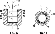
In einer bevorzugten Ausführungsform ist der Elektrolytkondensator mittels eines Klemmrings in der Ausnehmung festgehalten. Dadurch kann vorteilhaft ein Elektrolytkondensator Anwendung finden, welcher keine Rippen aufweisen braucht. Der Elektrolytkondensator weist in dieser Ausführungsform beispielsweise einen Gehäusebecher auf, welcher wenigstens im Bereich des wärmeleitenden Kontaktes mit der Ausnehmung zylinderförmig und glatt ausgebildet ist.In a preferred embodiment, the electrolytic capacitor is held in the recess by means of a clamping ring. As a result, it is advantageous to use an electrolytic capacitor which does not need to have any ribs. The electrolytic capacitor has in this embodiment, for example, a housing cup, which is cylindrical and smooth at least in the region of the heat-conducting contact with the recess.

Mittels des Klemmrings können vorteilhaft gewöhnliche Elektrolytkondensatoren mit einem Gehäusebecher mit dem Kühlkörper verbunden werden, wobei beispielsweise ein Anschlussdraht, welcher mit dem Gehäusebecher verbunden ist, vor einem Einfügen in die Ausnehmung abgeschnitten werden kann. Die Ausnehmung ist bevorzugt durch ein zylinderförmiges Sackloch gebildet. Das Sackloch kann beispielsweise im Bereich eines Bodens eine Vertiefung oder Mulde aufweisen, in die ein Rest eines abgeschnittenen Anschlussdrahtes wenigstens teilweise eingeführt werden kann. Dadurch kann ein Boden des Gehäusebechers nicht beim Einpressen verformt werden, da der Rest des Anschlussdrahtes einen Boden der Ausnehmung nicht berühren kann.By means of the clamping ring, it is possible with advantage to connect ordinary electrolytic capacitors with a housing cup to the heat sink, wherein, for example, a connection wire, which is connected to the housing cup, can be cut off before being inserted into the recess. The recess is preferably formed by a cylindrical blind hole. The blind hole may, for example, in the region of a bottom have a depression or depression, into which a remainder of a cut-off connecting wire can be at least partially inserted. As a result, a bottom of the housing cup can not be deformed during pressing, since the rest of the connecting wire can not touch a bottom of the recess.

In einer bevorzugten Ausführungsform ist der Klemmring auf einer Mantelfläche des Klemmrings zu einem Ende hin verjüngt, insbesondere konisch ausgebildet. Der Elektrolytkondensator kann so vorteilhaft zusammen mit dem verjüngt oder konisch ausgebildeten Klemmring in eine zuvor beschriebene sich zu einem Boden des Sacklochs hin verjüngende Ausnehmung eingepresst werden.In a preferred embodiment, the clamping ring is tapered on an outer surface of the clamping ring to one end, in particular conical. The electrolytic capacitor can be so advantageous pressed together with the tapered or conical clamping ring in a previously described to a bottom of the blind hole tapered recess.

In einer bevorzugten Ausführungsform ist der Klemmring in Umfangsrichtung wellenförmig und insbesondere zu einer Längsachse des Kondensators radial federnd ausgebildet. Der Gehäusebecher weist wenigstens auf einem Umfangsabschnitt eine Nut auf, wobei die Nut ausgebildet ist, den Klemmring wenigstens teilweise aufzunehmen, sodass der Klemmring in die Nut federnd eingreifen kann. Durch den Klemmring kann der Gehäusebecher vorteilhaft formschlüssig in der Ausnehmung festgehalten werden. Der Klemmring ist bevorzugt ausgebildet, mit einer radial abweisenden Welle in eine Nut der Ausnehmung federnd eingreifen. Die Ausnehmung kann dazu vorteilhaft eine radial umlaufende Ringnut aufweisen, welche zum Eingriff des Klemmrings ausgebildet ist. Auf diese Weise kann der Klemmring vor einem Einfügen des Elektrolytkondensators in die Ausnehmung über den Gehäusebecher geschoben werden, bis der Klemmring mit wenigstens einem bevorzugt wellenförmig radial nach innen weisenden Ringumfangsabschnitt in die zuvor beschriebene Nut des Gehäusebechers einschnappt. Der Gehäusebecher kann dann zusammen mit dem wellenförmigen Klemmring in die Ausnehmung eingefügt werden. Im Falle einer ringförmig umlaufenden Nut in der Ausnehmung kann der Klemmring mit einem radial nach außen weisenden Umfangsabschnitt in die Nut der Ausnehmung einrasten. Der Gehäusebecher ist so kraftschlüssig und zusätzlich formschlüssig in der Ausnehmung festgehalten.In a preferred embodiment, the clamping ring is wavy in the circumferential direction and in particular radially resiliently formed to a longitudinal axis of the capacitor. The housing cup has at least on a peripheral portion a groove, wherein the groove is formed to receive the clamping ring at least partially, so that the clamping ring can engage resiliently in the groove. By the clamping ring of the housing cup can be advantageously held positively in the recess. The clamping ring is preferably designed to resiliently engage with a radially deflecting shaft in a groove of the recess. The recess may advantageously have a radially encircling annular groove, which is designed for engagement of the clamping ring. In this way, the clamping ring can be pushed into the recess above the housing cup prior to insertion of the electrolytic capacitor until the clamping ring snaps into the previously described groove of the housing cup with at least one preferably radially inwardly directed circumferential ring section. The housing cup can then be inserted into the recess together with the wave-shaped clamping ring. In the case of an annular circumferential groove in the recess of the clamping ring can engage with a radially outwardly facing peripheral portion in the groove of the recess. The housing cup is so strong and additionally positively held in the recess.

In einer bevorzugten Ausführungsform weist der Klemmring wenigstens eine Federlasche auf, welche ausgebildet ist, gegen den Gehäusebecher und/oder eine Wand der Ausnehmung federnd abzustützen. Dazu kann der Klemmring beispielsweise radial nach außen weisende, und/oder radial nach innen weisende Federlaschen aufweisen. Vorteilhaft weisen die Federlaschen jeweils eine Schneide auf, wobei die Schneide ausgebildet ist, beim Einführen des Gehäusebechers in den Klemmring schabend in eine Oberfläche des Gehäusebechers einzugraben. Die Federlaschen, welche radial abweisen können beispielsweise schabend in die Wand der Ausnehmung eingreifen. Vorteilhaft erstrecken sich die radial abweisenden Federlaschen zu einer Öffnung der Ausnehmung hin, sodass beim Bewegen des Gehäusebechers in Richtung der Öffnung die Federlaschen mit den zuvor erwähnten Schneiden in die Wand der Ausnehmung einschneiden. Auf diese Weise ist eine Art Widerhaken gebildet, welcher ein wieder herausziehen des Elektrolytkondensators, beispielsweise durch Vibrationen oder Erschütterungen, verhindert. Die Federlaschen, welche radial nach innen weisen, weisen bevorzugt mit einer Richtungskomponente zu dem Boden des Gehäusebechers hin, sodass bei einer Kraft auf den Gehäusebecher, die gerichtet ist den Gehäusebecher aus der Öffnung herauszubewegen, die Federlaschen in die Oberfläche des Gehäusebechers einschneiden und wie zuvor beschrieben nach Art eines Widerhakens ein Herausbewegen des Gehäusebechers aus dem Klemmring verhindern.In a preferred embodiment, the clamping ring has at least one spring tab, which is designed to resiliently bear against the housing cup and / or a wall of the recess. For this purpose, the clamping ring, for example, radially outwardly facing, and / or radially inwardly facing spring tabs. Advantageously, the spring tabs each have a cutting edge, wherein the cutting edge is designed to scrape when inserting the housing cup in the clamping ring in a surface of the housing cup. The spring tabs, which deflect radially, for example, can intervene schabend in the wall of the recess. Advantageously, extend the radially repellent spring tabs to an opening of the recess, so that when moving the housing cup in the direction of the opening, the spring tabs cut with the aforementioned cutting in the wall of the recess. In this way, a kind of barbs is formed which prevents the electrolytic capacitor from being pulled out again, for example by vibrations or vibrations. The spring tabs pointing radially inward preferably face a directional component toward the bottom of the housing cup so that with a force on the housing cup directed to move the housing cup out of the opening, the spring tabs will cut into the surface of the housing cup and as before described in the manner of a barb prevent it from moving out of the housing cup from the clamping ring.

In einer bevorzugten Ausführungsform ist der Gehäusebecher in der Ausnehmung mit einem mindestens wärmeleitfähigen, oder zusätzlich elektrisch leitfähigen Medium, insbesondere einem Klebstoff, einer Paste oder einem Gel, in die Ausnehmung eingefügt, im Falle des Klebstoffs eingeklebt. Durch das Medium kann vorteilhaft ein guter Wärmeübergangswiderstand vom Gehäusebecher zu der Wand der Ausnehmung gebildet sein. Der Klebstoff ist beispielsweise durch ein Harz, insbesondere ein Acrylharz oder ein Epoxidharz gebildet. Das Harz kann beispielsweise mittels Ultraviolettstrahlung oder mittels einer radialhaltigen Startersubstanz zum Aushärten, insbesondere Auspolymerisieren gebracht werden. Der elektrisch leitfähige Klebstoff kann beispielsweise elektrisch leitfähige Partikel aufweisen, deren Anteil und Partikeldurchmesser im Klebstoff derart ausgebildet ist, dass zwischen dem Gehäusebecher und dem Kühlkörper im Bereich der Ausnehmung eine ununterbrochen elektrisch und wärmeleitfähige Kette von elektrisch leitfähigen Partikeln gebildet ist, wobei die elektrisch leitfähigen Partikel als Bestandteil der Kette einander berührend kontaktieren. Die Partikel sind beispielsweise Silberpartikel oder Kohlenstoffpartikel, insbesondere Carbonfaserabschnitte oder Carbon-Nanoröhrchen.In a preferred embodiment, the housing cup in the recess with an at least thermally conductive, or additionally electrically conductive medium, in particular an adhesive, a paste or a gel, inserted into the recess, glued in the case of the adhesive. The medium can advantageously be used to form a good heat transfer resistance from the housing cup to the wall of the recess. The adhesive is formed, for example, by a resin, in particular an acrylic resin or an epoxy resin. The resin can be brought to curing, in particular by polymerization, for example by means of ultraviolet radiation or by means of a radially containing starter substance. The electrically conductive adhesive may, for example, comprise electrically conductive particles whose proportion and particle diameter in the adhesive is such that an uninterrupted electrically and thermally conductive chain of electrically conductive particles is formed between the housing cup and the heat sink in the region of the recess, the electrically conductive particles contact each other as part of the chain. The particles are, for example, silver particles or carbon particles, in particular carbon fiber sections or carbon nanotubes.

Die Erfindung wird nun im Folgenden anhand von Figuren und weiteren Ausführungsbeispielen beschrieben. Weitere vorteilhafte Ausführungsvarianten ergeben sich aus den in den abhängigen Ansprüchen und in den Figuren genannten Merkmalen.The invention will now be described below with reference to figures and further embodiments. Further advantageous embodiments will become apparent from the features mentioned in the dependent claims and in the figures.

1 zeigt schematisch ein Ausführungsbeispiel für einen Elektrolytkondensator, welcher in einer Ausnehmung eines Kühlkörpers angeordnet ist und von Rippen des Kühlkörpers in der Ausnehmung kontaktiert wird; 1 schematically shows an embodiment of an electrolytic capacitor, which is arranged in a recess of a heat sink and is contacted by ribs of the heat sink in the recess;

2 zeigt schematisch den in 1 dargestellten Elektrolytkondensator in einem Querschnitt; 2 schematically shows the in 1 illustrated electrolytic capacitor in a cross section;

3 zeigt schematisch ein Einpressen des in 1 dargestellten Elektrolytkondensators in die Ausnehmung mittels eines Presswerkzeugs; 3 shows schematically a pressing of the in 1 shown electrolytic capacitor in the recess by means of a pressing tool;

4 zeigt schematisch einen in der Ausnehmung eines Kühlkörpers mittels eines Klemmrings festgehaltenen Kondensators; 4 shows schematically a captured in the recess of a heat sink by means of a clamping ring capacitor;

5 zeigt schematisch den in 4 dargestellten Kondensator in einem Querschnitt; 5 schematically shows the in 4 illustrated capacitor in a cross section;

6 zeigt schematisch einen in der Ausnehmung eines Kühlkörpers mittels eines längsgerippten Klemmrings festgehaltenen Kondensators; 6 shows schematically a captured in the recess of a heat sink by means of a longitudinally ribbed clamping ring capacitor;

7 zeigt schematisch den in 6 dargestellten Kondensator in einem Querschnitt; 7 schematically shows the in 6 illustrated capacitor in a cross section;

8 zeigt schematisch einen in der Ausnehmung eines Kühlkörpers mittels eines konisch ausgebildeten Klemmrings festgehaltenen Kondensators; 8th shows schematically a captured in the recess of a heat sink by means of a conical clamping ring capacitor;

9 zeigt schematisch den in 8 dargestellten Kondensator in einem Querschnitt; 9 schematically shows the in 8th illustrated capacitor in a cross section;

10 zeigt schematisch einen in der Ausnehmung eines Kühlkörpers mittels eines Klemmrings mit Federlaschen festgehaltenen Kondensators; 10 shows schematically a captured in the recess of a heat sink by means of a clamping ring with spring tabs capacitor;

11 zeigt schematisch den in 10 dargestellten Kondensator in einem Querschnitt; 11 schematically shows the in 10 illustrated capacitor in a cross section;

12 zeigt schematisch einen in der Ausnehmung eines Kühlkörpers mittels eines wellenförmigen Klemmrings festgehaltenen Kondensators; 12 shows schematically a captured in the recess of a heat sink by means of a wave-shaped clamping ring capacitor;

13 zeigt schematisch den in 12 dargestellten Kondensator in einem Querschnitt; 13 schematically shows the in 12 illustrated capacitor in a cross section;

14 zeigt schematisch einen in der Ausnehmung eines Kühlkörpers mittels eines mehrere Federbügel aufweisenden Klemmrings festgehaltenen Kondensators; 14 shows schematically a captured in the recess of a heat sink by means of a plurality of spring clip clamping ring held capacitor;

15 zeigt eine Variante des in 14 dargestellten Klemmrings in einer Aufsicht; 15 shows a variant of in 14 shown clamping ring in a plan view;

16 zeigt schematisch den in 14 dargestellten Kondensator in einem Querschnitt; 16 schematically shows the in 14 illustrated capacitor in a cross section;

17 zeigt einen Elektrolytkondensator der mittels einer Tellerfeder in einer Aussparung eines Kühlkörpers mit dem Kühlkörper verbunden ist; 17 shows an electrolytic capacitor which is connected by means of a disc spring in a recess of a heat sink to the heat sink;

18 zeigt die in 17 dargestellte Tellerfeder teilweise in einer Aufsicht; 18 shows the in 17 partially shown plate spring in a plan view;

19 zeigt einen Elektrolytkondensator der mittels eines wärmeleitfähigen und zusätzlich elektrisch leitfähigen Klebstoffs in einer Aussparung eines Kühlkörpers mit dem Kühlkörper verbunden ist; 19 shows an electrolytic capacitor by means of a thermally conductive and in addition electrically conductive adhesive is connected in a recess of a heat sink to the heat sink;

20 zeigt ein Ausführungsbeispiel für einen Elektrolytkondensator mit einem Gehäusebecher mit Rippen, die über einen Längsabschnitt des Gehäusebechers eine Art Zahnrad bilden; 20 shows an embodiment of an electrolytic capacitor with a housing cup with ribs, which form a kind of gear over a longitudinal portion of the housing cup;

21 zeigt ein Ausführungsbeispiel für einen Elektrolytkondensator mit einem Gehäusebecher mit einem Gewinde zum Einschrauben des Elektrolytkondensators in eine Aussparung eines Kühlkörpers. 21 shows an embodiment of an electrolytic capacitor with a housing cup with a thread for screwing the electrolytic capacitor in a recess of a heat sink.

1 zeigt ein Ausführungsbeispiel für einen Elektrolytkondensator 1, welcher in einer Ausnehmung 8 eines Kühlkörpers 5 angeordnet ist. Der Elektrolytkondensator 1 weist einen Anschluss 7 auf, welcher im Inneren des Elektrolytkondensators 1 mit einer positiven Elektrode des Elektrolytkondensators 1 verbunden ist. Der Elektrolytkondensator 1 weist auch einen in diesem Ausführungsbeispiel zylinderförmig ausgebildeten Gehäusebecher 3 auf, welcher im Inneren des Elektrolytkondensators 1 mit einer negativen Elektrode des Elektrolytkondensators 1 verbunden ist. Die Ausnehmung 8 des Kühlkörpers 5 ist in diesem Ausführungsbeispiel hohlzylinderförmig ausgebildet. Der Kühlkörper 5 weist radial umlaufend an einer Wand der Ausnehmung sich radial nach innen erstreckende Rippen auf. Die Rippen 10 und 11 sind beispielhaft bezeichnet. Der Elektrolytkondensator 1 weist in diesem Ausführungsbeispiel am Boden des Gehäusebechers 3 einen abgeschnittenen Anschluss 6 auf, welcher sich – wie der Anschluss 7 entlang einer Längsachse 20 des Elektrolytkondensators 1 erstreckt. Die Rippen 10 und 11 erstrecken sich jeweils in Richtung einer Tiefe der Ausnehmung 8 bis hin zu einem Boden der Ausnehmung 8, welche in diesem Ausführungsbeispiel als Sackloch ausgebildet ist. Am Boden der Ausnehmung 8 weist der Kühlkörper 5 eine weitere Vertiefung 9 auf, welche ausgebildet ist, den nach dem Abschneiden des Anschlussdrahtes des Gehäusebechers 3 verbleibenden Anschlussrest 6 aufzunehmen, nachdem der Kondensator 1 in die Ausnehmung 8 eingeschoben wurde. 1 shows an embodiment of an electrolytic capacitor 1 which is in a recess 8th a heat sink 5 is arranged. The electrolytic capacitor 1 has a connection 7 on which inside the electrolytic capacitor 1 with a positive electrode of the electrolytic capacitor 1 connected is. The electrolytic capacitor 1 also has a cylindrical in this embodiment formed housing cup 3 on which inside the electrolytic capacitor 1 with a negative electrode of the electrolytic capacitor 1 connected is. The recess 8th of the heat sink 5 is formed in this embodiment, a hollow cylinder. The heat sink 5 has radially circumferentially on a wall of the recess radially inwardly extending ribs. Ribs 10 and 11 are designated by way of example. The electrolytic capacitor 1 has in this embodiment at the bottom of the housing cup 3 a cut off connection 6 on which - like the connection 7 along a longitudinal axis 20 of the electrolytic capacitor 1 extends. Ribs 10 and 11 each extend in the direction of a depth of the recess 8th to a bottom of the recess 8th , which is formed in this embodiment as a blind hole. At the bottom of the recess 8th has the heat sink 5 another depression 9 which is formed after the cutting of the lead wire of the housing cup 3 remaining connection remainder 6 record after the capacitor 1 into the recess 8th was inserted.

Ein Boden des Gehäusebechers 3 gerät nach dem Einschieben des Kondensators 1 in die Ausnehmung 8 mit dem Boden der Ausnehmung 8 in wärmeleitenden Wirkkontakt. Der Gehäusebecher 3 steht auch im Bereich der Rippen mit dem Gehäusebecher 3, insbesondere einer Außenwand des Gehäusebechers 3 auf dem Längsabschnitt, über den sich die Rippen – in Richtung der Längsachse 20 – erstrecken, in wärmeleitendem Wirkkontakt. So kann Wärme sowohl über die Rippen als auch über den Boden der Ausnehmung 8 von dem Gehäusebecher 3 in den Kühlkörper 5 geleitet werden.A bottom of the housing cup 3 device after inserting the capacitor 1 into the recess 8th with the bottom of the recess 8th in thermally conductive active contact. The case mug 3 is also in the area of the ribs with the housing cup 3 , in particular an outer wall of the housing cup 3 on the longitudinal section, over which the ribs - in the direction of the longitudinal axis 20 - extend, in thermally conductive active contact. So heat can be transmitted both over the ribs and over the bottom of the recess 8th from the case cup 3 in the heat sink 5 be directed.

Zusätzlich zu dem bereits beschriebenen Kontakt zwischen dem Boden des Gehäusebechers 3 und dem Boden der Ausnehmung 8 durch Berühren kann zwischen dem Boden des Gehäusebechers 3 und dem Boden der Ausnehmung 8 ein Wärmeleitmittel 40, zuvor auch wärmeleitfähiges Medium genannt, angeordnet sein. Das Wärmeleitmittel ist beispielsweise eine Wärmeleitpaste oder ein wärmeleitfähiger oder zusätzlich elektrisch leitfähiger Klebstoff. Mittels des Wärmeleitmittels 40 kann ein zwischen dem Boden des Gehäusebechers 3 und dem Boden der Ausnehmung 8 befindlicher Luftspalt überbrückt werden. Der Gehäusebecher 3 des Kondensators 1 kann sich vorteilhaft bei thermischen Ausdehnungen in Hohlräume zwischen den Rippen hinein expandieren. Der Gehäusebecher 3 wird auch in dieser Ausführungsform vorteilhaft nur im Bereich der Rippen während eines Einpressens leicht eingedrückt und federnd festgehalten.In addition to the already described contact between the bottom of the housing cup 3 and the bottom of the recess 8th by touching it can be between the bottom of the housing cup 3 and the bottom of the recess 8th a heat transfer agent 40 , previously also called thermally conductive medium may be arranged. The heat conducting means is for example a thermal paste or a thermally conductive or additionally electrically conductive adhesive. By means of the heat transfer medium 40 can one between the bottom of the housing cup 3 and the bottom of the recess 8th be bridged air gap. The case mug 3 of the capacitor 1 can advantageously expand in thermal expansions in cavities between the ribs in. The case mug 3 is pressed in this embodiment, only slightly pressed in the region of the ribs during insertion and resiliently.

2 zeigt den in 1 bereits in einer Längsschnittdarstellung dargestellten Kondensator 1 in einer Querschnittdarstellung. Dargestellt ist der positive Anschlussdraht 7, der Gehäusebecher 3 und die Ausnehmung 8 des Kühlkörpers 5. Dargestellt sind auch die in 1 bereits gezeigten sich längserstreckenden Rippen 10 und 11. Die Rippen 10 und 11 erstrecken sich jeweils entlang eines Abschnitts einer Tiefenabmessung der Ausnehmung 8. So kann der Kondensator 1 in die Ausnehmung 8 entlang der Längsachse 20 eingeführt werden, bis ein Rand des Bodens des Gehäusebechers 3 die Rippen, insbesondere zu einer Öffnung der Ausnehmung 8 hingewandte Begrenzung der Rippen berührt. Zum weiteren Einschieben des Kondensators 1 ist dann eine Einpresskraft erforderlich, durch welche die Rippen in den Gehäusebecher eindrücken und den Gehäusebecher 3 so kraftschlüssig entlang der Längsachse 20 festhalten. 2 shows the in 1 already shown in a longitudinal sectional view capacitor 1 in a cross-sectional view. Shown is the positive connection wire 7 , the housing cup 3 and the recess 8th of the heat sink 5 , Shown are also in 1 already shown longitudinally extending ribs 10 and 11 , Ribs 10 and 11 each extend along a portion of a depth dimension of the recess 8th , So can the capacitor 1 into the recess 8th along the longitudinal axis 20 be inserted until an edge of the bottom of the housing cup 3 the ribs, in particular to an opening of the recess 8th wielded boundary of the ribs touched. For further insertion of the capacitor 1 then a pressing force is required through which the ribs press into the housing cup and the housing cup 3 so frictionally along the longitudinal axis 20 hold tight.

3 zeigt den in 1 und in 2 bereits dargestellten Kondensator 1, welcher von einem Einpresswerkzeug 30 in eine Ausnehmung des Kühlkörpers 5 eingepresst worden ist. Das Einpresswerkzeug 30 umgreift dabei den Gehäusebecher 3 des Kondensators 1 im Bereich des Anschlusses 7 und greift in eine in einer Becherwand des Gehäusebechers gebildete Vertiefung, insbesondere eine umlaufend ausgebildete Nut ein. Dargestellt ist die in 2 bereits gezeigte Ausnehmung 8, die Rippe 11, und die Vertiefung 9. 3 shows the in 1 and in 2 already shown capacitor 1 , which of a press tool 30 in a recess of the heat sink 5 has been pressed. The press tool 30 encloses the case cup 3 of the capacitor 1 in the area of the connection 7 and engages in a recess formed in a cup wall of the housing cup, in particular a circumferentially formed groove. Shown is the in 2 already shown recess 8th , the rib 11 , and the depression 9 ,

4 zeigt ein Ausführungsbeispiel, bei dem der in 1 bereits dargestellte Kondensator 1 umfassend den Gehäusebecher 3 und den Anschluss 7 in eine Ausnehmung 22 eines Kühlkörpers 5 eingefügt ist. Die Ausnehmung 22 ist in diesem Ausführungsbeispiel entlang eines Tiefenabschnitts beginnend von einer Öffnung der Ausnehmung 22 zylinderförmig ausgebildet. Die Ausnehmung 22 ist im weiteren Verlauf entlang einer Tiefenerstreckung sich verjüngend ausgebildet. 4 shows an embodiment in which the in 1 already shown capacitor 1 comprising the housing cup 3 and the connection 7 in a recess 22 a heat sink 5 is inserted. The recess 22 is in this embodiment along a depth section starting from an opening of the recess 22 cylindrically shaped. The recess 22 is formed laterally tapering along a depth extension.

Ein Durchmesser der Ausnehmung 22 am Boden der Ausnehmung 22 ist größer als ein Durchmesser des Gehäusebechers 3 des Kondensators 1, sodass sich der Kondensator 1 zunächst ohne weitere Einpresskräfte in die Ausnehmung 22 einfügen lässt. Nach einem Einfügen des Kondensators 1 in die Ausnehmung 22 kann ein Klemmring 16, welcher in diesem Ausführungsbeispiel als Rohrabschnitt ausgebildet ist, in die Ausnehmung 22 eingepresst werden. Der Klemmring 16 verformt sich dabei in der Ausnehmung durch die zuvor beschriebene zunehmende Verjüngung und die so gebildete Konizität der Ausnehmung zum Boden hin. Der Klemmring 16 drückt dabei auch in den Gehäusebecher 3 auf einem Längsabschnitt der Verjüngung der Ausnehmung 22 ein und sichert den Kondensator 1 so formschlüssig gegen ein Herausbewegen aus der Ausnehmung 22 entlang einer Längsachse 20 des Kondensators 1. A diameter of the recess 22 at the bottom of the recess 22 is larger than a diameter of the housing cup 3 of the capacitor 1 so that the capacitor 1 initially without further pressing forces into the recess 22 insert. After inserting the capacitor 1 into the recess 22 can be a clamping ring 16 , which is formed in this embodiment as a pipe section, in the recess 22 be pressed. The clamping ring 16 Deformed in the recess by the above-described increasing taper and the conicity of the recess thus formed towards the ground. The clamping ring 16 also presses into the housing cup 3 on a longitudinal portion of the taper of the recess 22 and secures the capacitor 1 so positively against a move out of the recess 22 along a longitudinal axis 20 of the capacitor 1 ,

5 zeigt den in 4 bereits dargestellten Kondensator 1 in der Ausnehmung 22. Die Ausnehmung 22 weist in diesem Ausführungsbeispiel im Bereich der Tiefenabmessung sich entlang der Tiefe erstreckende Nuten auf. Die Nut 13 ist beispielhaft bezeichnet. Die Nuten bewirken, dass beim Einpressen des Klemmrings 16 Luft, welche durch den Klemmring 16 komprimiert werden würde, durch die Nuten entweichen kann. 5 shows the in 4 already shown capacitor 1 in the recess 22 , The recess 22 has in this embodiment in the depth dimension along the depth extending grooves. The groove 13 is designated by way of example. The grooves cause when pressing the clamping ring 16 Air passing through the clamping ring 16 would be compressed, can escape through the grooves.

6 zeigt ein Ausführungsbeispiel für einen Kühlkörper 5 mit einer Ausnehmung 24, welche in diesem Ausführungsbeispiel zylinderförmig ausgebildet ist. 6 shows an embodiment of a heat sink 5 with a recess 24 which is cylindrical in this embodiment.

In der Ausnehmung 24 ist der in 1 bereits beschriebene Kondensator 1 umfassend den Gehäusebecher 3 und den Anschluss 7 vollständig aufgenommen. Die Ausnehmung 24 weist einen größeren Durchmesser auf als der Gehäusebecher 3 des Kondensators 1. Dadurch lässt sich der Kondensator 1 ohne zusätzliche Einpresskraft in die Ausnehmung 24 einfügen. Zwischen einer Außenwand des Gehäusebechers 3 und einer Innenwand der Ausnehmung 24 ist entlang einem Längsabschnitt der Ausnehmung 24 – in Tiefenerstreckung der Ausnehmung 24 – ein Klemmring 15 angeordnet. Der Klemmring 15 ist nach einem Einfügen des Kondensators 1 in die Ausnehmung 24 zwischen dem Gehäusebecher 3 und die Innenwand der Ausnehmung 24 eingepresst worden. Der Klemmring 15 ist ausgebildet, den Gehäusebecher 3 wärmeleitend zu berühren oder zusätzlich einzupressen und Wärme von dem Gehäusebecher 3 an den Kühlkörper 5 über die Innenwand der Ausnehmung 24 zu leiten. Der Gehäusebecher 3 kann – wie bereits in 1 dargestellt – im Bereich eines Bodens mit einem Boden der Ausnehmung 24 in thermisch leitfähigem Wirkkontakt stehen. Dazu kann zusätzlich zu einem Berühren des Bodens des Gehäusebechers 3 mit dem Kühlkörper 5 ein Wärmeleitmittel 40 zwischen dem Boden des Gehäusebechers und einem Boden der Ausnehmung 24 angeordnet sein.In the recess 24 is the in 1 already described capacitor 1 comprising the housing cup 3 and the connection 7 completely recorded. The recess 24 has a larger diameter than the housing cup 3 of the capacitor 1 , This allows the capacitor 1 without additional pressing force into the recess 24 insert. Between an outer wall of the housing cup 3 and an inner wall of the recess 24 is along a longitudinal portion of the recess 24 - In depth extension of the recess 24 - a clamping ring 15 arranged. The clamping ring 15 is after an insertion of the capacitor 1 into the recess 24 between the housing cup 3 and the inner wall of the recess 24 been pressed. The clamping ring 15 is formed, the housing cup 3 heat-conducting touch or in addition to press and heat from the housing cup 3 to the heat sink 5 over the inner wall of the recess 24 to lead. The case mug 3 can - as already in 1 represented - in the region of a bottom with a bottom of the recess 24 are in thermally conductive active contact. This may be in addition to touching the bottom of the housing cup 3 with the heat sink 5 a heat transfer agent 40 between the bottom of the housing cup and a bottom of the recess 24 be arranged.

7 zeigt den in 6 bereits in einer Längsschnittdarstellung dargestellten Kondensator 1 in der Ausnehmung 24 in einer Querschnittdarstellung. Dargestellt sind der Gehäusebecher 3, der Anschluss 7, die Ausnehmung 24 und der Klemmring 15. Der Klemmring 15 weist eine radial nach außen weisende, umlaufende glatte Begrenzung auf, welche mit der zuvor beschriebenen Innenwand der Ausnehmung 24 glatt abschließt. Der Klemmring 15 weist radial nach innen weisende sich längserstreckende Rippen auf, welche wie zuvor bereits in den 1, 2 und 3 beschrieben ausgebildet sein können. Die Rippen des Klemmrings 15 sind ausgebildet, beim Einpressen des Klemmrings 15 die Gehäusewand des Gehäusebechers 3 auf einem Längsabschnitt des Kondensators 1 einzupressen und so federnd kraftschlüssig festzuhalten. Die Rippen des Klemmrings 15 sind weiter ausgebildet, den Gehäusebecher 3 im Bereich der Berührungsstellen wärmeleitend oder zusätzlich elektrisch zu kontaktieren, und von dem Gehäusebecher 3 aufgenommene Wärme an den Kühlkörper 5 über die Innenwand abzugeben. 7 shows the in 6 already shown in a longitudinal sectional view capacitor 1 in the recess 24 in a cross-sectional view. Shown are the housing cup 3 , the connection 7 , the recess 24 and the clamping ring 15 , The clamping ring 15 has a radially outwardly facing, circumferential smooth boundary, which with the above-described inner wall of the recess 24 smoothly completes. The clamping ring 15 has radially inwardly facing longitudinally extending ribs, which as previously in the 1 . 2 and 3 may be formed described. The ribs of the clamping ring 15 are formed when pressing the clamping ring 15 the housing wall of the housing cup 3 on a longitudinal section of the capacitor 1 press in and thus hold resiliently frictionally. The ribs of the clamping ring 15 are further formed, the housing cup 3 in the region of the contact points heat-conducting or in addition to electrically contact, and of the housing cup 3 absorbed heat to the heat sink 5 to deliver over the inner wall.

8 zeigt ein Ausführungsbeispiel für eine Ausnehmung 23 in einem Kühlkörper 5. Die Ausnehmung 23 ist von einer Öffnung an beginnend entlang eines Tiefenabschnitts der Ausnehmung 23 zylinderförmig ausgebildet. Die Ausnehmung 23 ist im weiteren Verlauf entlang der Tiefe bis hin zu einem Boden konisch mit zum Boden hin abnehmendem Durchmesser ausgebildet. Der Durchmesser der Ausnehmung 23 ist in diesem Ausführungsbeispiel am Boden größer als der Durchmesser des Gehäusebechers 3 am Boden des Kondensators 1. Dadurch lässt sich der Kondensator 1 ohne zusätzliche Einpresskräfte in die Ausnehmung 23 einführen. Der Kondensator 1 wird in einem weiteren Schritt mit einem Klemmring 14 in der Ausnehmung 23 festgeklemmt. Der Klemmring 14 ist dazu an einer Innenwand zylinderförmig ausgebildet, sodass der – in diesem Ausführungsbeispiel zylinderförmig ausgebildete – Gehäusebecher 3 nach einem Einführen des Klemmrings 14 in die Ausnehmung und einem Überstülpen über den Kondensator 1 von der Innenwand des Klemmrings 1 thermisch und zusätzlich elektrisch leitend kontaktiert werden kann. Der Klemmring 14 weist einen entlang einer Längserstreckung entlang der Längsachse 20 des Klemmrings sich verringernden Außendurchmesser auf. Dadurch ist eine Außenwand des Klemmrings 14 kreiskegelförmig gebildet. Zusätzlich zu der Wärmeleitung von dem Gehäusebecher 3 über den Klemmring 14 an den Kühlkörper 5 kann der Boden des Gehäusebechers 3 – wie bereits zuvor beschrieben – mittels eines Wärmeleitmittels 40 an einem Boden der Ausnehmung 23 wärmeleitend angebunden sein. 8th shows an embodiment of a recess 23 in a heat sink 5 , The recess 23 is from an opening beginning along a depth portion of the recess 23 cylindrically shaped. The recess 23 is further formed along the depth to a bottom conical with decreasing diameter towards the bottom. The diameter of the recess 23 is greater in this embodiment at the bottom than the diameter of the housing cup 3 at the bottom of the capacitor 1 , This allows the capacitor 1 without additional pressing forces into the recess 23 introduce. The capacitor 1 is in a further step with a clamping ring 14 in the recess 23 clamped. The clamping ring 14 For this purpose, it is cylindrical on an inner wall, so that the - in this embodiment, cylindrically shaped - housing cup 3 after insertion of the clamping ring 14 in the recess and a slipping over the capacitor 1 from the inner wall of the clamping ring 1 thermally and additionally electrically conductive can be contacted. The clamping ring 14 has one along a longitudinal extent along the longitudinal axis 20 of the clamping ring decreasing outer diameter. This is an outer wall of the clamping ring 14 formed in a circle. In addition to the heat conduction from the housing cup 3 over the clamping ring 14 to the heat sink 5 may be the bottom of the housing cup 3 - As already described above - by means of a Wärmeleitmittels 40 at a bottom of the recess 23 be thermally connected.

9 zeigt den bereits in 8 in einem Längsschnitt dargestellten Kondensator 1 in einer Querschnittdarstellung. Dargestellt sind der Gehäusebecher 3 und der Anschluss 7. Die zuvor beschriebene Buchse 14 weist entlang eines Umlaufes einen Schlitz auf, sodass mögliche Toleranzen im Durchmesser des Gehäusebechers 3 und/oder dem Durchmesser der bereits beschriebenen Ausnehmung 23 ausgeglichen werden können. 9 shows the already in 8th in a longitudinal section shown capacitor 1 in a cross-sectional view. Shown are the housing cup 3 and the connection 7 , The previously described socket 14 has a slot along one revolution, so possible tolerances in the diameter of the housing cup 3 and / or the diameter of the recess already described 23 can be compensated.

Durch die zuvor in 8 beschriebene Keilform im Längsschnitt des Klemmrings 14 kann beim Einpressen des Klemmrings 14 eine gasdichte Verbindung zwischen dem Klemmring 14 und dem Gehäusebecher 3 und dem Klemmring 14 und einer Innenwand der Ausnehmung 23 des Kühlkörpers 5 erreicht werden. Durch die gasdichte Verbindung ist ein guter elektrischer Kontakt zwischen dem Gehäusebecher 3 und dem Kühlkörper 5 über den in diesem Ausführungsbeispiel elektrisch- und wärmeleitfähigen Klemmring 14 hergestellt, der durch die Gasdichtigkeit vor Oxidation geschützt ist.By the previously in 8th described wedge shape in the longitudinal section of the clamping ring 14 can when pressing the clamping ring 14 a gas-tight connection between the clamping ring 14 and the housing cup 3 and the clamping ring 14 and an inner wall of the recess 23 of the heat sink 5 be achieved. Due to the gas-tight connection is a good electrical contact between the housing cup 3 and the heat sink 5 over the electrically and thermally conductive clamping ring in this embodiment 14 manufactured, which is protected by the gas-tightness from oxidation.

10 zeigt ein Ausführungsbeispiel für einen Kühlkörper 5 mit einer Ausnehmung 24. Die Ausnehmung 24 ist – wie zuvor in 6 beschrieben – zylinderförmig ausgebildet. Der Kondensator 1 umfassend den Gehäusebecher 3 und der Anschluss 7 weist einen kleineren Durchmesser als die Ausnehmung 24 auf, sodass der Kondensator 1 sich ohne zusätzliche Einpresskräfte in die Ausnehmung 24 einfügen lässt. Der Gehäusebecher 3 des Kondensators 1 ist in diesem Ausführungsbeispiel vollständig in der Ausnehmung 24 aufgenommen. Der Kondensator 1 ist durch einen Klemmring 17 in der Ausnehmung 24 festgehalten. Der Klemmring 17 weist radial nach außen abweisende Federlaschen 34 und radial nach innen weisende Federlaschen 32 auf. Nach einem Einpressen des Klemmrings 17 entlang der Längsachse 20 drücken die Federlaschen 32, welche radial nach innen weisen, gegen eine Wand des Gehäusebechers 3 und die Federlaschen 34, welche radial nach außen weisen, gegen die Wand der Ausnehmung 24. Der Gehäusebecher 3 steht mit einem Boden der Ausnehmung 24 in wärmeleitfähigem Wirkkontakt. Der Klemmring 17 ist beispielsweise elektrisch leitfähig ausgebildet, sodass mittels des Klemmrings 17 eine elektrische Verbindung zwischen dem Gehäusebecher 3 und dem Kühlkörper 5 über die Wand der Ausnehmung 24 hergestellt ist. 10 shows an embodiment of a heat sink 5 with a recess 24 , The recess 24 is - as before in 6 described - cylindrical. The capacitor 1 comprising the housing cup 3 and the connection 7 has a smaller diameter than the recess 24 on, so the capacitor 1 without additional pressing forces in the recess 24 insert. The case mug 3 of the capacitor 1 is completely in the recess in this embodiment 24 added. The capacitor 1 is through a clamping ring 17 in the recess 24 recorded. The clamping ring 17 has radially outwardly repellent spring tabs 34 and radially inwardly facing spring tabs 32 on. After pressing in the clamping ring 17 along the longitudinal axis 20 press the spring tabs 32 , which point radially inward, against a wall of the housing cup 3 and the spring tabs 34 facing radially outward against the wall of the recess 24 , The case mug 3 stands with a bottom of the recess 24 in thermally conductive active contact. The clamping ring 17 is, for example, electrically conductive, so that by means of the clamping ring 17 an electrical connection between the housing cup 3 and the heat sink 5 over the wall of the recess 24 is made.

Die Federlaschen 34 erstrecken sich mit einer Richtungskomponente radial nach außen und mit einer Richtungskomponente zu einer Öffnung der Ausnehmung 34 hin. Dadurch kann der Klemmring 17 in die Ausnehmung 24 eingefügt werden. Die zur Öffnung der Ausnehmung 24 hin gerichteten Federlaschen bilden so eine Art Widerhaken, sodass der Klemmring 17 gegen ein Herausbewegen des Klemmrings 17 entlang der Längsachse 20 gesichert ist. Die Federlaschen 32 weisen mit einer Richtungskomponente radial nach innen und mit einer Richtungskomponente zu einem Boden der Ausnehmung 24 hin. Dadurch lässt sich der Gehäusebecher 3 des Kondensators in den Kontaktring 17 einpressen. Der Gehäusebecher 3 des Kondensators ist gegen ein Herausbewegen aus dem Kontaktring 17 und der Ausnehmung 24 wie bereits beschrieben durch die mittels der Federlaschen 32 gebildeten Widerhaken gesichert.The spring tabs 34 extend with a direction component radially outward and with a directional component to an opening of the recess 34 out. This allows the clamping ring 17 into the recess 24 be inserted. The opening of the recess 24 directed towards the spring tabs form a kind of barbs, so that the clamping ring 17 against a moving out of the clamping ring 17 along the longitudinal axis 20 is secured. The spring tabs 32 point with a directional component radially inward and with a directional component to a bottom of the recess 24 out. This allows the housing cup 3 of the capacitor in the contact ring 17 Pressing. The case mug 3 the capacitor is against moving out of the contact ring 17 and the recess 24 as already described by means of the spring tabs 32 secured barbs secured.

11 zeigt den in 10 in einer Längsschnittdarstellung dargestellten Kondensator 1 in der Ausnehmung 24 in einer Querschnittdarstellung. Dargestellt ist der Gehäusebecher 3 und der Anschluss 7 des Kondensators 1. Der Klemmring 17 weist mehrere, in diesem Ausführungsbeispiel neun radial nach außen weisende Federlaschen 34 und neun radial nach innen weisende Federlaschen 32 auf. 11 shows the in 10 in a longitudinal section shown capacitor 1 in the recess 24 in a cross-sectional view. Shown is the housing cup 3 and the connection 7 of the capacitor 1 , The clamping ring 17 has several, in this embodiment, nine radially outwardly facing spring tabs 34 and nine radially inwardly facing spring tabs 32 on.

12 zeigt ein Ausführungsbeispiel für einen Kondensator 1, welcher in einer zylinderförmig ausgebildeten Ausnehmung 24 eines Kühlkörpers 5 angeordnet ist. Die Ausnehmung 24 weist zusätzlich zu der in 10 dargestellten Ausnehmung 24 zwei ringförmig ausgebildete Nuten auf, welche radial umlaufend nach außen ausgebildet sind und die Ausnehmung 24 jeweils entlang eines Tiefenabschnitts entlang der Längsachse 20 radial nach außen erweitern. Der Gehäusebecher 3 des Kondensators 1 weist zwei radial nach innen weisende und umlaufend ausgebildete Nuten, nämlich eine im Bereich des Anschlusses 7 verlaufende Nut 38, und eine entlang des Längserstreckungskondensators 1 zwischen einem Boden des Gehäusebechers 3 und einem Rand des Gehäusebechers angeordnete Nut 39 auf. Der Gehäusebecher 3 des Kondensators 1 ist in diesem Ausführungsbeispiel in der Ausnehmung 24 vollständig aufgenommen. Der Kühlkörper 5 weist eine radial nach außen weisende und ringförmig umlaufende Nut 42 auf, welche entlang der Längsachse 20 der Nut 38 gegenüber angeordnet ist. Der Kühlkörper 5 weist auch eine Nut 41 auf, welche die Ausnehmung 24 radial nach außen erweitert und welche entlang der Längsachse 20 der Nut 39 gegenüberliegend angeordnet ist. Der Gehäusebecher 3 des Kondensators 1 ist in diesem Ausführungsbeispiel mittels eines Klemmrings 18 und eines Klemmrings 19 formschlüssig gegen ein Herausbewegen entlang der Längsachse 20 aus der Ausnehmung 24 gesichert. Die Klemmringe 18 und 19 sind jeweils entlang eines Ringumlaufes wellenförmig ausgebildet, sodass sich entlang des Ringumlaufes ein Ringabschnitt radial nach außen und ein darauf folgender Ringabschnitt radial nach innen erstreckt. Die radial nach innen erstreckenden Ringabschnitte können dabei in die Nut 38 eingreifen, die radial nach außen erstreckenden Ringabschnitte können in die der Nut 38 gegenüberliegende Nut 42 des Kühlkörpers 5 eingreifen. 12 shows an embodiment of a capacitor 1 , which in a cylindrical recess 24 a heat sink 5 is arranged. The recess 24 indicates in addition to the in 10 illustrated recess 24 two annular grooves formed, which are formed radially circumferentially outward and the recess 24 each along a depth section along the longitudinal axis 20 expand radially outward. The case mug 3 of the capacitor 1 has two radially inwardly facing and circumferentially formed grooves, namely one in the region of the terminal 7 running groove 38 , and one along the longitudinal extension capacitor 1 between a bottom of the housing cup 3 and a rim of the housing cup arranged groove 39 on. The case mug 3 of the capacitor 1 is in this embodiment in the recess 24 completely recorded. The heat sink 5 has a radially outwardly facing and annular circumferential groove 42 on, which along the longitudinal axis 20 the groove 38 is arranged opposite. The heat sink 5 also has a groove 41 on which the recess 24 extended radially outward and which along the longitudinal axis 20 the groove 39 is arranged opposite. The case mug 3 of the capacitor 1 is in this embodiment by means of a clamping ring 18 and a clamping ring 19 positively against a move along the longitudinal axis 20 from the recess 24 secured. The clamping rings 18 and 19 are each wave-shaped along a circular revolution, so that extends along the annular circulation, a ring portion radially outward and a subsequent ring portion radially inwardly. The radially inwardly extending ring sections can thereby into the groove 38 engage, the radially outwardly extending annular portions can in the groove 38 opposite groove 42 of the heat sink 5 intervention.

Der Klemmring 18 greift somit in die Nut 38 des Gehäusebechers und in die Nut 42 des Kühlkörpers 5 ein. Der Klemmring 19 greift auf dieselbe Weise in die Nut 39 des Gehäusebechers 3 und in die Nut 41 des Kühlkörpers 5 ein. Die Klemmringe 18 und 19 können beispielsweise vor einem Einschieben des Kondensators 1 in die Ausnehmung 24 eingefügt sein. Der Kondensator 1 kann dann anschließend in die Nut 24 eingeschoben werden, wobei der Kondensator 1 bei einer Übereinstimmung der Nuten des Kühlkörpers 5 mit den Nuten des Gehäusebechers 3 mit den Klemmringen 18 und 19 in formschlüssigen Wirkeingriff gerät. Die Klemmringe 18 und 19 rasten dann in die Nuten 38 beziehungsweise 39 ein. The clamping ring 18 thus engages in the groove 38 of the housing cup and into the groove 42 of the heat sink 5 one. The clamping ring 19 engages in the same way in the groove 39 of the housing cup 3 and in the groove 41 of the heat sink 5 one. The clamping rings 18 and 19 For example, before inserting the capacitor 1 into the recess 24 be inserted. The capacitor 1 then can then into the groove 24 be pushed, the capacitor 1 at a coincidence of the grooves of the heat sink 5 with the grooves of the housing cup 3 with the clamping rings 18 and 19 in positive-locking action device. The clamping rings 18 and 19 then snap into the grooves 38 respectively 39 one.

13 zeigt den in 12 bereits als Längsschnitt dargestellten Kondensator 1 in der Ausnehmung 24 in einem Querschnitt. Dargestellt ist der Gehäusebecher 3 und der Anschluss 7 des Kondensators 1. Weiter dargestellt sind die Ausnehmung 24 des Kühlkörpers 5 und der Klemmring 18. Der Klemmring 18 ist beispielsweise elektrisch leitfähig oder zusätzlich wärmeleitfähig ausgebildet. Dadurch kann Wärme im Bereich der durch die Nuten 38 und 39 gebildeten Einschnürungen des Gehäusebechers 3 über den Klemmring 18 und den Klemmring 19 an den Kühlkörper 15 abgeführt werden. Der Gehäusebecher 3 kann auch mittels der Klemmringe 18 und 19 mit dem Kühlkörper 5 elektrisch verbunden sein. 13 shows the in 12 already shown as a longitudinal section capacitor 1 in the recess 24 in a cross section. Shown is the housing cup 3 and the connection 7 of the capacitor 1 , Further illustrated are the recess 24 of the heat sink 5 and the clamping ring 18 , The clamping ring 18 is, for example, electrically conductive or additionally thermally conductive. This can heat in the area through the grooves 38 and 39 formed constrictions of the housing cup 3 over the clamping ring 18 and the clamping ring 19 to the heat sink 15 be dissipated. The case mug 3 can also by means of the clamping rings 18 and 19 with the heat sink 5 be electrically connected.

Zusätzlich zu der thermischen Kontaktierung des Gehäusebechers 3 über die Klemmringe 18 und 19 kann ein Boden des Gehäusebechers 3 – wie zuvor in 1 beschrieben – mittels eines Wärmeleitmittels 40 mit einem Boden der Ausnehmung 24 in wärmeleitendem Wirkkontakt stehen.In addition to the thermal contacting of the housing cup 3 over the clamping rings 18 and 19 can be a bottom of the housing cup 3 - as previously in 1 described - by means of a Wärmeleitmittels 40 with a bottom of the recess 24 be in thermally conductive active contact.

14 zeigt ein Ausführungsbeispiel für einen Kondensator 1 mit einem Gehäusebecher 3 und einem Anschluss 7. Der Kondensator 1 ist mit dem Gehäusebecher 3 vollständig in eine Ausnehmung 25 des Kühlkörpers 5 angeordnet. Zwischen einer Außenfläche des Gehäusebechers 3 und einer Innenwand der Ausnehmung 25 ist ein Klemmring 21 angeordnet. Der Klemmring 21 weist konvex radial nach außen weisende Federbügel auf und radial nach innen konvex ausgebildete Federbügel auf. Der radial nach außen weisende Federbügel 35 und der radial nach innen weisende Federbügel 36 sind beispielhaft bezeichnet. 14 shows an embodiment of a capacitor 1 with a housing cup 3 and a connection 7 , The capacitor 1 is with the housing cup 3 completely in a recess 25 of the heat sink 5 arranged. Between an outer surface of the housing cup 3 and an inner wall of the recess 25 is a clamping ring 21 arranged. The clamping ring 21 has convexly radially outwardly facing spring clip on and radially inwardly convex spring clip on. The radially outwardly facing spring clip 35 and the radially inwardly facing spring clip 36 are designated by way of example.

Der Klemmring 21 ist in 15 in einer Aufsicht dargestellt. Der Klemmring 21 kann vor einem Einsetzen des Kondensators 1 in die Ausnehmung 25 auf den Gehäusebecher 3 des Kondensators 1 aufgeschoben werden. Beispielsweise weist der Klemmring 21 – in 15 nicht dargestellte – Federlaschen 37 auf, welche ausgebildet sind, in die zuvor beschriebene Nut 39 des Gehäusebechers einzugreifen. Dadurch ist nach einem Einrasten der Federlaschen 37 in die Nut 39 der Klemmring 21 entlang der Längsachse 20 gegen ein Verschieben entlang der Längsachse 20 auf dem Gehäusebecher 3 formschlüssig gesichert. Nach dem Aufschieben des Klemmrings 21 auf dem Gehäusebecher 3 kann der Kondensator 1 zusammen mit dem Klemmring 21 in die Ausnehmung 25 eingeführt werden. Der Klemmring 21 kann beispielsweise entlang seines Ringumfanges eine Öffnung aufweisen. Die Ausnehmung 25 kann – gestrichelt dargestellt – entlang einer Tiefenerstreckung einen Bereich aufweisen, welcher einen kleineren Durchmesser aufweist als ein entlang der Tiefenerstreckung benachbarter Bereich der Ausnehmung 25. Der Klemmring 21 kann dann in die Ausnehmung 25 unter radialer Komprimierung eingeführt werden und schnappt dann radial nach außen federnd in den Bereich der Ausnehmung 25 mit größerem Durchmesser ein. Der Kondensator 1 kann dann anschließend in die Ausnehmung 25 eingeführt werden und drückt dann die Federbügel 36 radial nach außen. Die Federlaschen 37 ragen dann in den noch verbleibenden Zwischenraum zwischen dem Gehäusebecher 3 und einer Wand der Ausnehmung 25 in den Bereich mit kleinerem Durchmesser. Die Federlaschen 37 rasten dann in die Ringnut 39 ein und sichern den Kondensator 1 formschlüssig gegen ein Herausbewegen aus der Ausnehmung 25 entlang der Längsachse 20.The clamping ring 21 is in 15 shown in a top view. The clamping ring 21 can be before inserting the capacitor 1 into the recess 25 on the housing mug 3 of the capacitor 1 be deferred. For example, the clamping ring 21 - in 15 not shown - spring clips 37 which are formed in the above-described groove 39 to engage the housing cup. As a result, after a latching of the spring tabs 37 in the groove 39 the clamping ring 21 along the longitudinal axis 20 against displacement along the longitudinal axis 20 on the case mug 3 positively secured. After pushing on the clamping ring 21 on the case mug 3 can the capacitor 1 together with the clamping ring 21 into the recess 25 be introduced. The clamping ring 21 For example, it may have an opening along its circumference. The recess 25 can - shown in dashed lines - along a depth extension having a region which has a smaller diameter than a depth along the extension of the adjacent region of the recess 25 , The clamping ring 21 can then into the recess 25 are introduced under radial compression and then snaps radially outward into the region of the recess 25 with a larger diameter. The capacitor 1 can then subsequently into the recess 25 are introduced and then presses the spring clip 36 radially outward. The spring tabs 37 then protrude into the remaining space between the housing cup 3 and a wall of the recess 25 in the area of smaller diameter. The spring tabs 37 then snap into the ring groove 39 and secure the capacitor 1 positively against a moving out of the recess 25 along the longitudinal axis 20 ,

16 zeigt eine Variante für einen Klemmring 27, welcher in dem in 14 bereits beschriebenen Bereich der Ausnehmung 25 mit größerem Durchmesser angeordnet ist. Der Klemmring 27 weist radial konvex nach innen ausgebildete Federbügel 31 auf. Die Federbügel 31 sind – ähnlich wie die Federbügel 35 in 15 – in Umfangsrichtung aufeinanderfolgend angeordnet. 16 shows a variant of a clamping ring 27 which is in the in 14 already described area of the recess 25 is arranged with a larger diameter. The clamping ring 27 has radially convex inwardly formed spring clip 31 on. The spring clips 31 are - similar to the spring clip 35 in 15 - Sequentially arranged in the circumferential direction.

Anders als in 15 sind in Umfangsrichtung unmittelbar aufeinanderfolgende Federbügel derart ausgeformt, dass die unmittelbar aufeinanderfolgenden Federbügel jeweils an zueinander verschiedenen Berührungsstellen entlang der Längsachse 20 den Gehäusebecher 3 federnd kontaktieren. Dadurch wird eine auf den Gehäusebecher 3 wirkende Anpresskraft auf einer Fläche des Gehäusebechers 3 verteilt. Weiter vorteilhaft wird eine Einpresskraft beim Einführen des Kondensators in die Aussparung in zeitlich zueinander versetzte Teilkräfte aufgeteilt.Unlike in 15 are circumferentially immediately successive spring clip formed such that the immediately successive spring clips each at mutually different points of contact along the longitudinal axis 20 the housing cup 3 contact resiliently. This will put one on the housing cup 3 acting contact pressure on a surface of the housing cup 3 distributed. Further advantageously, a press-in force during insertion of the capacitor is divided into the recess in mutually offset partial forces.

17 zeigt eine Ausführungsform für eine Verbindung des Kondensators 1 umfassend den Gehäusebecher 3 und den Anschluss 7 mit einem Kühlkörper 5, bei der der Kondensator 1 wenigstens entlang eines Längsabschnitts entlang der Längsachse 20 mit dem Gehäusebecher 3 in einer Tellerfeder 28 aufgenommen ist. Der Kondensator 1 ist zusammen mit der Tellerfeder 28 in der Ausnehmung 24 aufgenommen. 17 shows an embodiment for a connection of the capacitor 1 comprising the housing cup 3 and the connection 7 with a heat sink 5 in which the capacitor 1 at least along a longitudinal section along the longitudinal axis 20 with the housing cup 3 in a plate spring 28 is included. The capacitor 1 is together with the plate spring 28 in the recess 24 added.

Ein Boden des Gehäusebechers berührt dabei einen Boden der Tellerfeder 28. Die Tellerfeder 28 weist von dem Boden der Tellerfeder 28 sich senkrecht erstreckende Federlaschen 26 auf, welche sich jeweils entlang der Längsachse 20 erstrecken. Die Federlaschen 26 weisen jeweils einen konvex radial nach innen weisenden Längsabschnitt auf, welcher ausgebildet ist, den Gehäusebecher 3 federnd zu kontaktieren. Die Federlaschen 26 erstrecken sich jeweils im Bereich eines Endes radial nach außen, sodass die Federlaschen 26 im Bereich des Endes eine Wand des Kühlkörpers 5 im Bereich der Ausnehmung 24 kontaktieren können. Die Federlaschen 26 drücken dabei mit dem radial nach außen federnden Endabschnitt gegen die Wand der Ausnehmung 24 und mit dem radial nach innen weisenden Längsabschnitt gegen den Gehäusebecher 3.A bottom of the housing cup touches a bottom of the plate spring 28 , The plate spring 28 points from the bottom of the plate spring 28 vertically extending spring tabs 26 on, which are each along the longitudinal axis 20 extend. The spring tabs 26 each have a convex radially inwardly facing longitudinal portion, which is formed, the housing cup 3 resilient contact. The spring tabs 26 each extend in the region of one end radially outward, so that the spring tabs 26 in the region of the end of a wall of the heat sink 5 in the region of the recess 24 can contact. The spring tabs 26 Press with the radially outwardly resilient end portion against the wall of the recess 24 and with the radially inwardly facing longitudinal portion against the housing cup 3 ,

18 zeigt die in 18 dargestellte Tellerfeder 28 in einem Teilschnitt in einer Aufsicht. 18 shows the in 18 shown plate spring 28 in a partial section in a supervision.

19 zeigt ein Ausführungsbeispiel für einen Kondensator 1 umfassend einen Gehäusebecher 3 und einen Anschluss 7, welcher in einer Ausnehmung 24 angeordnet ist. Die Ausnehmung 24 ist zylinderförmig ausgebildet. Der Gehäusebecher 3 des Kondensators 1 ist in diesem Ausführungsbeispiel mittels eines elektrisch leitfähigen und wärmeleitfähigen Klebstoffs 40 in die Ausnehmung 24 eingeklebt. Der elektrisch leitfähige Klebstoff kann dazu beispielsweise elektrisch leitfähige Partikel aufweisen, deren Anteil und Partikeldurchmesser im Klebstoff derart ausgebildet ist, dass zwischen dem Gehäusebecher 3 und dem Kühlkörper 5 im Bereich der Ausnehmung 24 eine ununterbrochen elektrisch und wärmeleitfähige Kette von elektrisch leitfähigen Partikeln gebildet ist, wobei die elektrisch leitfähigen Partikel als Bestandteil der Kette einander berührend kontaktieren. Durch die berührende Kontaktierung ist ein galvanischer elektrischer Kontakt zwischen den einander berührenden Partikeln gebildet. Die Partikel sind beispielsweise Silberpartikel und/oder Kohlenstoffpartikel. 19 shows an embodiment of a capacitor 1 comprising a housing cup 3 and a connection 7 which is in a recess 24 is arranged. The recess 24 is cylindrical. The case mug 3 of the capacitor 1 is in this embodiment by means of an electrically conductive and thermally conductive adhesive 40 into the recess 24 glued. For this purpose, the electrically conductive adhesive may comprise, for example, electrically conductive particles whose proportion and particle diameter in the adhesive is such that between the housing cup 3 and the heat sink 5 in the region of the recess 24 a continuously electrically and thermally conductive chain of electrically conductive particles is formed, wherein the electrically conductive particles contact each other as part of the chain. As a result of the contacting contact, a galvanic electrical contact is formed between the mutually contacting particles. The particles are, for example, silver particles and / or carbon particles.

20 zeigt einen Elektrolytkondensator 2. Der Elektrolytkondensator 2 weist einen Gehäusebecher 47 und einen positiven Anschluss 7 auf. Der Gehäusebecher 47 weist einen Bereich auf, an dem sich längs in Richtung einer Längsachse 20 erstreckende und radial abweisende Rippen ausgebildet sind. Die Rippe 45 ist beispielhaft bezeichnet. Die Rippen sind jeweils in dem Gehäusebecher 47 – beispielsweise mittel Prägen oder bei einem Fließpressen des Gehäusebechers 47 – ausgeformt. Die Rippen sind jeweils ausgebildet, beim Einpressen in eine beispielsweise zylinderförmige Ausnehmung eines Kühlkörpers radial nach innen einzufedern und/oder radial nach innen plastisch verformt zu werden. Dadurch ist der Elektrolytkondensator in der Ausnehmung festgehalten und kontaktiert zusätzlich elektrisch und wärmeleitend den Kühlkörper. Die Rippen können dazu beispielsweise wenigstens eine radial abweisende Schneide oder Nadel aufweisen, welche ausgebildet ist, eine Oxidschicht einer Wand der Ausnehmung beim Einpressen des Elektrolytkondensators in die Ausnehmung zu durchbrechen und den Kühlkörper elektrisch zu kontaktieren. 20 shows an electrolytic capacitor 2 , The electrolytic capacitor 2 has a housing cup 47 and a positive connection 7 on. The case mug 47 has an area that extends longitudinally in the direction of a longitudinal axis 20 extending and radially repellent ribs are formed. The rib 45 is designated by way of example. The ribs are each in the housing cup 47 - For example, medium embossing or extruding the housing cup 47 - shaped. The ribs are each formed to be compressed radially inwardly during injection into an example cylindrical recess of a heat sink and / or to be plastically deformed radially inwardly. As a result, the electrolytic capacitor is held in the recess and also contacts the heat sink electrically and thermally conductive. For this purpose, the ribs may, for example, have at least one radially repellent cutting edge or needle, which is designed to break through an oxide layer of a wall of the recess when the electrolytic capacitor is pressed into the recess and to contact the cooling element electrically.

21 zeigt einen Elektrolytkondensator 4. Der Elektrolytkondensator 4 weist einen Gehäusebecher 48 und einen positiven Anschluss 7 auf. Der Gehäusebecher 48 bildet in diesem Ausführungsbeispiel einen negativen Anschluss des Elektrolytkondensators 4. 21 shows an electrolytic capacitor 4 , The electrolytic capacitor 4 has a housing cup 48 and a positive connection 7 on. The case mug 48 forms in this embodiment, a negative terminal of the electrolytic capacitor 4 ,

Der Gehäusebecher 48 weist einen Längsabschnitt auf, an dem ein Gewinde ausgebildet ist. Dazu ist an den Gehäusebecher 48 ein sich ein radial nach außen erstreckender und radial abweisender Gewindegang 49 ausgebildet. Der Elektrolytkondensator 4 kann mit dem Gewindeabschnitt in eine entsprechend ausgebildete Ausnehmung eines Kühlkörpers eingeschraubt werden. Der Kühlkörper kann dazu in der Ausnehmung ein entsprechendes Gegengewinde aufweisen. The case mug 48 has a longitudinal portion on which a thread is formed. This is the case cup 48 a radially outwardly extending and radially deflecting thread 49 educated. The electrolytic capacitor 4 can be screwed with the threaded portion in a correspondingly formed recess of a heat sink. The heat sink may have in the recess a corresponding counter-thread.

Claims (12)

Kondensator (1, 2, 4), insbesondere Elektrolytkondensator, mit einem Gehäusebecher (3, 47, 48), dadurch gekennzeichnet, dass der Kondensator (1, 2, 4) mit einem Kühlkörper (5) derart verbunden ist, dass von dem Kondensator (1, 2, 4) erzeugte Wärme an den Kühlkörper (5) abgegeben werden kann, wobei der Kühlkörper (5) eine Ausnehmung (8, 22, 23, 24, 25) aufweist, in welcher der Kondensator (1, 2, 4) wenigstens teilweise aufgenommen ist und der Gehäusebecher (3, 47, 48) in der Ausnehmung (8, 22, 23, 24, 25) mit dem Kühlkörper (5) wenigstens wärmeleitend verbunden ist.Capacitor ( 1 . 2 . 4 ), in particular electrolytic capacitor, with a housing cup ( 3 . 47 . 48 ), characterized in that the capacitor ( 1 . 2 . 4 ) with a heat sink ( 5 ) is connected in such a way that of the capacitor ( 1 . 2 . 4 ) generated heat to the heat sink ( 5 ), wherein the heat sink ( 5 ) a recess ( 8th . 22 . 23 . 24 . 25 ), in which the capacitor ( 1 . 2 . 4 ) is at least partially received and the housing cup ( 3 . 47 . 48 ) in the recess ( 8th . 22 . 23 . 24 . 25 ) with the heat sink ( 5 ) is connected at least thermally conductive. Kondensator (1, 2, 4) nach Anspruch 1, dadurch gekennzeichnet, dass der Kühlkörper (5) elektrisch leitfähig ausgebildet ist und der Kondensator (1, 2, 4) insbesondere der Gehäusebecher (3, 47, 48) in der Ausnehmung (8, 22, 23, 24, 25) mit dem Kühlkörper (5) elektrisch verbunden ist.Capacitor ( 1 . 2 . 4 ) according to claim 1, characterized in that the heat sink ( 5 ) is electrically conductive and the capacitor ( 1 . 2 . 4 ) in particular the housing cup ( 3 . 47 . 48 ) in the recess ( 8th . 22 . 23 . 24 . 25 ) with the heat sink ( 5 ) is electrically connected. Kondensator (1, 2, 4) nach Anspruch 1 oder 2, dadurch gekennzeichnet, dass der Kondensator (1, 2, 4) in die Ausnehmung derart eingepresst ist, dass eine Wand der Ausnehmung (8, 22, 23, 24, 25) von wenigstens einem Bereich des Gehäusebechers (3, 47, 48) wärmeleitend oder zusätzlich elektrisch kontaktiert ist.Capacitor ( 1 . 2 . 4 ) according to claim 1 or 2, characterized in that the capacitor ( 1 . 2 . 4 ) is pressed into the recess such that a wall of the recess ( 8th . 22 . 23 . 24 . 25 ) of at least a portion of the housing cup ( 3 . 47 . 48 ) is thermally conductive or additionally electrically contacted. Kondensator (1, 2, 4) nach Anspruch 3, dadurch gekennzeichnet, dass die Ausnehmung (23) wenigstens auf einem Abschnitt nach innen konisch verlaufend ausgebildet ist. Capacitor ( 1 . 2 . 4 ) according to claim 3, characterized in that the recess ( 23 ) Is designed to taper at least on a portion inwardly. Kondensator (1, 2, 4) nach Anspruch 3 oder 4, dadurch gekennzeichnet, dass der Kondensator (2) wenigstens auf einem zum Einpressen ausgebildeten Abschnitt radial abweisende, bevorzugt sich entlang der Längsachse erstreckende Rippen (45) aufweist, welche ausgebildet sind, den Kühlkörper (5) im Bereich der Ausnehmung (8, 22, 23, 24, 25) wärmeleitend oder zusätzlich elektrisch zu kontaktieren und den Kondensator (2) in der Ausnehmung (8, 22, 23, 24, 25) insbesondere federnd festzuklemmen.Capacitor ( 1 . 2 . 4 ) according to claim 3 or 4, characterized in that the capacitor ( 2 ) at least on a section formed for pressing radially repellent, preferably along the longitudinal axis extending ribs ( 45 ), which are formed, the heat sink ( 5 ) in the region of the recess ( 8th . 22 . 23 . 24 . 25 ) thermally conductive or in addition to electrically contact and the capacitor ( 2 ) in the recess ( 8th . 22 . 23 . 24 . 25 ) in particular resiliently clamp. Kondensator (1, 2, 4) nach Anspruch 3 oder 4, dadurch gekennzeichnet, dass der Kühlkörper (5) in der Ausnehmung (8) ausgeformte Rippen (10, 11) aufweist, welche ausgebildet sind, den Gehäusebecher festzuhalten.Capacitor ( 1 . 2 . 4 ) according to claim 3 or 4, characterized in that the heat sink ( 5 ) in the recess ( 8th ) shaped ribs ( 10 . 11 ), which are designed to hold the housing cup. Kondensator (1) nach einem der vorhergehenden Ansprüche, dadurch gekennzeichnet, dass der Kondensator mittels eines Klemmringes (14, 15, 16, 17, 18, 19, 21, 27) in der Ausnehmung (8, 22, 23, 24, 25) festgehalten ist.Capacitor ( 1 ) according to one of the preceding claims, characterized in that the capacitor by means of a clamping ring ( 14 . 15 . 16 . 17 . 18 . 19 . 21 . 27 ) in the recess ( 8th . 22 . 23 . 24 . 25 ) is recorded. Kondensator (1) nach Anspruch 7, dadurch gekennzeichnet, dass der Klemmring (14) auf einer Mantelfläche des Klemmrings (14) zu einem Ende hin verjüngt ausgebildet ist.Capacitor ( 1 ) according to claim 7, characterized in that the clamping ring ( 14 ) on a lateral surface of the clamping ring ( 14 ) is tapered to one end. Kondensator (1) nach Anspruch 7, dadurch gekennzeichnet, dass der Klemmring (18, 19) in Umfangsrichtung wellenförmig ausgebildet ist, und der Gehäusebecher (3) wenigstens auf einem Umfangsabschnitt eine Nut (38, 39) aufweist, welche ausgebildet ist, den Klemmring (18, 19) wenigstens teilweise aufzunehmen, so dass der Klemmring (18, 19) in die Nut (38, 39) eingreifen kann.Capacitor ( 1 ) according to claim 7, characterized in that the clamping ring ( 18 . 19 ) is wave-shaped in the circumferential direction, and the housing cup ( 3 ) at least on a peripheral portion of a groove ( 38 . 39 ), which is formed, the clamping ring ( 18 . 19 ) at least partially, so that the clamping ring ( 18 . 19 ) into the groove ( 38 . 39 ) can intervene. Kondensator (1) nach einem der Ansprüche 7 bis 9, dadurch gekennzeichnet, dass der Klemmring (17) wenigstens eine Federlasche (32, 34) aufweist, welche ausgebildet ist, gegen den Gehäusebecher (3) und/oder eine Wand der Ausnehmung (24) federnd abzustützen.Capacitor ( 1 ) according to one of claims 7 to 9, characterized in that the clamping ring ( 17 ) at least one spring tab ( 32 . 34 ), which is formed against the housing cup ( 3 ) and / or a wall of the recess ( 24 ) resiliently support. Kondensator (1, 2, 4) nach einem der vorhergehenden Ansprüche, dadurch gekennzeichnet, dass der Gehäusebecher (3) in der Ausnehmung (8, 24, 25) mit einem mindestens wärmeleitfähigen oder zusätzlich elektrisch leitfähigen Klebstoff (40) in die Ausnehmung (24) eingeklebt ist.Capacitor ( 1 . 2 . 4 ) according to one of the preceding claims, characterized in that the housing cup ( 3 ) in the recess ( 8th . 24 . 25 ) with an at least thermally conductive or additionally electrically conductive adhesive ( 40 ) in the recess ( 24 ) is glued. Kondensator (1, 2, 4) nach einem der vorhergehenden Ansprüche, dadurch gekennzeichnet, dass der Gehäusebecher (48) eine Gewinde (49) aufweist und in die Aussparung eingeschraubt werden kann.Capacitor ( 1 . 2 . 4 ) according to one of the preceding claims, characterized in that the housing cup ( 48 ) a thread ( 49 ) and can be screwed into the recess.
DE201110081283 2011-08-19 2011-08-19 Capacitor with a heat sink Withdrawn DE102011081283A1 (en)

Priority Applications (4)

Application Number Priority Date Filing Date Title
DE201110081283 DE102011081283A1 (en) 2011-08-19 2011-08-19 Capacitor with a heat sink
EP12743426.4A EP2745300B1 (en) 2011-08-19 2012-07-24 Capacitor having a heat sink
PCT/EP2012/064543 WO2013026645A2 (en) 2011-08-19 2012-07-24 Capacitor having a heat sink
CN201280040526.1A CN103748644B (en) 2011-08-19 2012-07-24 There is the capacitor of radiator

Applications Claiming Priority (1)

Application Number Priority Date Filing Date Title
DE201110081283 DE102011081283A1 (en) 2011-08-19 2011-08-19 Capacitor with a heat sink

Publications (1)

Publication Number Publication Date
DE102011081283A1 true DE102011081283A1 (en) 2013-02-21

Family

ID=46614463

Family Applications (1)

Application Number Title Priority Date Filing Date
DE201110081283 Withdrawn DE102011081283A1 (en) 2011-08-19 2011-08-19 Capacitor with a heat sink

Country Status (4)

Country Link
EP (1) EP2745300B1 (en)
CN (1) CN103748644B (en)
DE (1) DE102011081283A1 (en)
WO (1) WO2013026645A2 (en)

Cited By (9)

* Cited by examiner, † Cited by third party
Publication number Priority date Publication date Assignee Title
DE102015203791A1 (en) * 2015-03-03 2016-09-08 Ebm-Papst Mulfingen Gmbh & Co. Kg Multifunction housing for electronic components
DE102015111541A1 (en) * 2015-07-16 2017-01-19 Halla Visteon Climate Control Corporation System for installing at least one cylindrical electrolytic capacitor on a heat sink and method for producing a compound
DE102017223631A1 (en) 2017-12-21 2019-06-27 Robert Bosch Gmbh Inverter for an electric machine
DE102018201120A1 (en) * 2018-01-24 2019-07-25 Dr. Ing. H.C. F. Porsche Ag On-board charger of an electric or hybrid vehicle
US20190304711A1 (en) * 2018-03-30 2019-10-03 Avx Corporation Supercapacitor Assembly having a Barrier Layer
DE102018121945A1 (en) * 2018-09-07 2020-03-12 Seg Automotive Germany Gmbh Power module for an inverter, inverter and method for producing a power module
DE102018121919A1 (en) * 2018-09-07 2020-03-12 Seg Automotive Germany Gmbh Power module for an inverter, inverter and method for producing a power module
DE102018218219A1 (en) * 2018-10-24 2020-04-30 Hanon Systems Efp Deutschland Gmbh Electric water pump
FR3126278A1 (en) * 2021-08-20 2023-02-24 Psa Automobiles Sa ELECTRICAL DEVICE PROTECTED AGAINST LIQUID SPRAYS

Families Citing this family (9)

* Cited by examiner, † Cited by third party
Publication number Priority date Publication date Assignee Title
US9025315B2 (en) * 2013-03-06 2015-05-05 Cooper Technologies Company Electrochemical energy storage device with flexible metal current collector
CN205212748U (en) * 2015-11-30 2016-05-04 中山大洋电机股份有限公司 Motor controller
CN106535532A (en) * 2016-12-27 2017-03-22 成都芯通科技股份有限公司 Positioning and installing device and positioning method for circuit system
JPWO2019064897A1 (en) * 2017-09-29 2020-10-15 日本電産株式会社 motor
CN109148763B (en) * 2018-08-03 2021-04-06 六安志成智能科技有限公司 New forms of energy power battery fixed knot constructs
JP7469956B2 (en) * 2020-05-27 2024-04-17 Tdk株式会社 Electronic Components
CN114551091B (en) * 2020-11-18 2025-07-29 上海汽车电驱动有限公司 Capacitor device for BSG system and mounting structure
DE102022111476A1 (en) 2022-05-09 2023-11-09 Tdk Electronics Ag Capacitor component, use of a capacitor component and method of production
CN118919295B (en) * 2024-10-10 2024-12-13 胜业电气股份有限公司 Power capacitor with high safety performance

Citations (13)

* Cited by examiner, † Cited by third party
Publication number Priority date Publication date Assignee Title
DE4038689A1 (en) * 1990-12-05 1992-06-11 Standard Elektrik Lorenz Ag Support clamp for cylindrical electrical capacitor - uses sleeve fitted to carrier plate enclosing outside of capacitor
JPH04223319A (en) * 1990-12-25 1992-08-13 Matsushita Electric Ind Co Ltd Aluminum electrolytic capacitor
DE9213103U1 (en) * 1992-09-29 1992-11-12 Siemens Matsushita Components GmbH & Co. KG, 8000 München Electrolytic capacitor for high AC load capacity
DE9212421U1 (en) * 1992-09-15 1994-01-27 Siemens AG, 80333 München Device for dissipating the heat loss in power capacitors
US5373418A (en) * 1990-03-28 1994-12-13 Mitsubishi Denki Kabushiki Kaisha Electrical device for mounting electrical components with enhanced thermal radiating properties
JPH0864457A (en) * 1994-08-19 1996-03-08 Fujitsu General Ltd Condenser holder
US5940264A (en) * 1996-10-04 1999-08-17 Philips Electronics North America Corp Electrolytic capacitor with heat sink and method of heat dissipation
DE19817493C1 (en) * 1998-04-20 1999-08-26 Siemens Matsushita Components Aluminium electrolyte capacitor for capacitor battery
DE10009398A1 (en) * 2000-02-28 2001-09-06 Epcos Ag Plate-shaped heat-sink module for capacitor, comprises edge structures that allow coupling to similar modules in defined orientation
DE19857840C2 (en) * 1998-12-15 2003-10-02 Siemens Ag Electronic device
DE102007009315A1 (en) * 2006-02-22 2007-08-30 Behr Gmbh & Co. Kg Electrical component, e.g. lithium ion battery, cooling device for e.g. hybrid vehicle, has heat sink, and connection provided between guiding bodies and side surface of component and between guiding bodies and heat sink
DE102006025535A1 (en) * 2006-06-01 2007-12-06 Behr Gmbh & Co. Kg Device for cooling electrical elements
DE102009034051B3 (en) * 2009-07-21 2011-03-31 Siemens Aktiengesellschaft Holding element for use in mounting arrangement and for simultaneous fixing of multiple cylindrical condensers of condenser battery at cooling plate, has base plate and hoods, where base of each hood has two openings

Family Cites Families (3)

* Cited by examiner, † Cited by third party
Publication number Priority date Publication date Assignee Title
JPH06104143A (en) * 1992-09-21 1994-04-15 Nippon Chemicon Corp Electrolytic capacitor mounting device
DE19725843C1 (en) * 1997-06-18 1998-10-29 Siemens Matsushita Components Aluminium-electrolyte capacitor for AC operation
DE102005025832B3 (en) * 2005-06-02 2006-11-16 Aic Europe Elektronische Bauteile Gmbh Capacitor fixture arrangement e.g. for vertical mounting of electrolytic capacitors, has part-zone with connection device for connection of retainer body with support element

Patent Citations (13)

* Cited by examiner, † Cited by third party
Publication number Priority date Publication date Assignee Title
US5373418A (en) * 1990-03-28 1994-12-13 Mitsubishi Denki Kabushiki Kaisha Electrical device for mounting electrical components with enhanced thermal radiating properties
DE4038689A1 (en) * 1990-12-05 1992-06-11 Standard Elektrik Lorenz Ag Support clamp for cylindrical electrical capacitor - uses sleeve fitted to carrier plate enclosing outside of capacitor
JPH04223319A (en) * 1990-12-25 1992-08-13 Matsushita Electric Ind Co Ltd Aluminum electrolytic capacitor
DE9212421U1 (en) * 1992-09-15 1994-01-27 Siemens AG, 80333 München Device for dissipating the heat loss in power capacitors
DE9213103U1 (en) * 1992-09-29 1992-11-12 Siemens Matsushita Components GmbH & Co. KG, 8000 München Electrolytic capacitor for high AC load capacity
JPH0864457A (en) * 1994-08-19 1996-03-08 Fujitsu General Ltd Condenser holder
US5940264A (en) * 1996-10-04 1999-08-17 Philips Electronics North America Corp Electrolytic capacitor with heat sink and method of heat dissipation
DE19817493C1 (en) * 1998-04-20 1999-08-26 Siemens Matsushita Components Aluminium electrolyte capacitor for capacitor battery
DE19857840C2 (en) * 1998-12-15 2003-10-02 Siemens Ag Electronic device
DE10009398A1 (en) * 2000-02-28 2001-09-06 Epcos Ag Plate-shaped heat-sink module for capacitor, comprises edge structures that allow coupling to similar modules in defined orientation
DE102007009315A1 (en) * 2006-02-22 2007-08-30 Behr Gmbh & Co. Kg Electrical component, e.g. lithium ion battery, cooling device for e.g. hybrid vehicle, has heat sink, and connection provided between guiding bodies and side surface of component and between guiding bodies and heat sink
DE102006025535A1 (en) * 2006-06-01 2007-12-06 Behr Gmbh & Co. Kg Device for cooling electrical elements
DE102009034051B3 (en) * 2009-07-21 2011-03-31 Siemens Aktiengesellschaft Holding element for use in mounting arrangement and for simultaneous fixing of multiple cylindrical condensers of condenser battery at cooling plate, has base plate and hoods, where base of each hood has two openings

Cited By (15)

* Cited by examiner, † Cited by third party
Publication number Priority date Publication date Assignee Title
DE102015203791A1 (en) * 2015-03-03 2016-09-08 Ebm-Papst Mulfingen Gmbh & Co. Kg Multifunction housing for electronic components
US10741332B2 (en) 2015-07-16 2020-08-11 Hanon Systems Cooling of electrolytic capacitors in electrical climate compressors
DE102015111541A1 (en) * 2015-07-16 2017-01-19 Halla Visteon Climate Control Corporation System for installing at least one cylindrical electrolytic capacitor on a heat sink and method for producing a compound
US10410795B2 (en) 2015-07-16 2019-09-10 Hanon Systems Cooling of electrolytic capacitors in electrical climate compressors
DE102015111541B4 (en) 2015-07-16 2023-07-20 Halla Visteon Climate Control Corporation Method of making a connection between at least one cylindrical electrolytic capacitor and a heat sink
DE102017223631A1 (en) 2017-12-21 2019-06-27 Robert Bosch Gmbh Inverter for an electric machine
WO2019121317A1 (en) 2017-12-21 2019-06-27 Robert Bosch Gmbh Inverter for an electrical machine
US11316439B2 (en) 2017-12-21 2022-04-26 Robert Bosch Gmbh Inverter for an electrical machine
DE102018201120A1 (en) * 2018-01-24 2019-07-25 Dr. Ing. H.C. F. Porsche Ag On-board charger of an electric or hybrid vehicle
DE102018201120B4 (en) 2018-01-24 2024-12-12 Dr. Ing. H.C. F. Porsche Ag on-board charger of an electric or hybrid vehicle
US20190304711A1 (en) * 2018-03-30 2019-10-03 Avx Corporation Supercapacitor Assembly having a Barrier Layer
DE102018121919A1 (en) * 2018-09-07 2020-03-12 Seg Automotive Germany Gmbh Power module for an inverter, inverter and method for producing a power module
DE102018121945A1 (en) * 2018-09-07 2020-03-12 Seg Automotive Germany Gmbh Power module for an inverter, inverter and method for producing a power module
DE102018218219A1 (en) * 2018-10-24 2020-04-30 Hanon Systems Efp Deutschland Gmbh Electric water pump
FR3126278A1 (en) * 2021-08-20 2023-02-24 Psa Automobiles Sa ELECTRICAL DEVICE PROTECTED AGAINST LIQUID SPRAYS

Also Published As

Publication number Publication date
EP2745300B1 (en) 2016-01-20
WO2013026645A2 (en) 2013-02-28
WO2013026645A3 (en) 2013-04-11
EP2745300A2 (en) 2014-06-25
CN103748644B (en) 2016-12-07
CN103748644A (en) 2014-04-23

Similar Documents

Publication Publication Date Title
EP2745300B1 (en) Capacitor having a heat sink
KR101567355B1 (en) Arrangement and method for holding a plurality of electric capacitor assemblies
EP2226899B1 (en) Device for connecting two electrical conductors
CN114649721B (en) Bus bar contact for attachment to a bus bar and method for attaching a bus bar contact
DE102009030463A1 (en) Electrical connector
EP1291939A2 (en) Galvanic element comprising spirally wound electrode assembly
CN209344380U (en) Switch jaw contact part and current connector
DE102020211091A1 (en) Electrical contact connector and battery
DE112013004468T5 (en) Energy storage device
EP3161884A2 (en) Contact device for contacting an energy storage cell
DE112014001135T5 (en) Electrochemical energy storage device with flexible metal current collector
WO2007099124A1 (en) Lamp with a built-in lamp
DE102019115985B4 (en) BATTERY CONNECTION SYSTEM
EP1234361B1 (en) Gaz-filled surge diverter with electrode connections in the shape of band-type clips
EP2698874B1 (en) Contact system with a press-fit contact
DE112016006088T5 (en) ENERGY STORAGE DEVICE
CN218678764U (en) Slant rotor press-fitting tooling and skew rotor press-fit equipment
JP6704826B2 (en) Electronic component manufacturing method and electronic component
JP2009264428A (en) Rivet
DE102017131016A1 (en) Automatic crimping on sheet metal parts
DE102009040222A1 (en) Terminal for use at battery pole in vehicle, has spacer element providing radial spreading of clamping jaws and tensioning element i.e. spring, where spacer element is removed such that jaws and tensioning element are radially narrowed
KR20160132907A (en) Connector for electrically contacting arresters of an electrochemical cell
CN113258332A (en) Electrode connection structure and lamp
CN212062754U (en) PIN needle structure of prevention deformation
CN211026954U (en) Oil squeezing device

Legal Events

Date Code Title Description
R163 Identified publications notified
R005 Application deemed withdrawn due to failure to request examination