CN212593917U - Be applied to axle center magnetism of oblique commentaries on classics magic cube and inhale positioning mechanism - Google Patents
Be applied to axle center magnetism of oblique commentaries on classics magic cube and inhale positioning mechanism Download PDFInfo
- Publication number
- CN212593917U CN212593917U CN202020921870.3U CN202020921870U CN212593917U CN 212593917 U CN212593917 U CN 212593917U CN 202020921870 U CN202020921870 U CN 202020921870U CN 212593917 U CN212593917 U CN 212593917U
- Authority
- CN
- China
- Prior art keywords
- block
- magnet
- shaft
- magic cube
- positioning mechanism
- Prior art date
- Legal status (The legal status is an assumption and is not a legal conclusion. Google has not performed a legal analysis and makes no representation as to the accuracy of the status listed.)
- Active
Links
- 230000005389 magnetism Effects 0.000 title claims abstract description 9
- 238000000034 method Methods 0.000 abstract description 4
- 230000009286 beneficial effect Effects 0.000 description 1
- 230000009466 transformation Effects 0.000 description 1
Images


Landscapes
- Magnetic Treatment Devices (AREA)
Abstract
The utility model provides a be applied to positioning mechanism is inhaled to axle center magnetism of oblique magic cube, the oblique magic cube includes central axis body and block, magnetism is inhaled positioning mechanism including setting up in the axle center magnet of the axle center department of central axis body, and set up in the block bottom and with the corresponding block magnet of axle center magnet through setting up magnet respectively in the bottom of axle center and interior corner piece, has saved the inside space of interior corner piece main part, has also increaseed the moment of overcoming magnetic force at the in-process that rotates the magic cube for the rotation process is more smooth.
Description
Technical Field
The utility model relates to a magic cube, in particular to be applied to axle center magnetism of oblique commentaries on classics magic cube and inhale positioning mechanism.
Background
The oblique magic cube inherits the cubic structure of the positive-order magic cube, but one surface block is divided into five parts, namely four congruent isosceles right triangles and one square, by an inscribed square. The four corners are called corner blocks, the small square in the middle is called a center block, the small square rotates along one side of the square during rotation, the oblique magic cube needs to be accurately rotated by a player, and the magic cube needs to be rotated 120 degrees each time.
The magnetic positioning mechanism of the existing magic cube is magnets respectively arranged on the corner block and the central block, but the magnetic positioning mechanism is not suitable for the oblique magic cube, because the oblique magic cube mainly twists the corner block to drive other corner blocks and the central block to rotate, and if the magnets are arranged on the corner block and the central block, the moment required for overcoming the magnetic force when the corner block is rotated is too small, so that the restoring speed of the oblique magic cube is greatly influenced.
SUMMERY OF THE UTILITY MODEL
In order to solve the technical problem, the utility model provides a to one side magic cube with positioning mechanism is inhaled to magnetism aims at overcoming the required moment of magnetic force when the increase hornblock is rotatory.
The utility model discloses the technical scheme who adopts as follows:
the utility model provides a be applied to axle center magnetism of oblique commentaries on classics magic cube and inhale positioning mechanism, the oblique commentaries on classics magic cube includes central axis body and block, its characterized in that: the magnetic attraction positioning mechanism comprises an axis magnet arranged at the axis of the central axis body and a block magnet arranged at the bottom of the block and corresponding to the axis magnet.
Preferably, the block includes four outer corner pieces, with the center block of outer corner piece joint, and is located outer corner piece opposite direction one side and joint the inner corner piece of center block, the bottom of outer corner piece, center block and inner corner piece all is provided with the tongue of sliding base, the center axis body is special-shaped buckle axle, special-shaped buckle axle includes axostylus axostyle and axle center, the axostylus axostyle end is provided with the stopper, axle center magnet set up in with the terminal opposite direction one side of axostylus axostyle and be located the axle center department of special-shaped buckle axle, block magnet set up in inner corner piece bottom, block magnet along with every rotatory 120 degrees of oblique magic cube promptly with axle center magnet is relative.
Furthermore, the axis magnet is cylindrical, four cylindrical grooves for placing the axis magnet are arranged at the axis of the special-shaped buckle shaft, each cylindrical groove is coaxial with one shaft rod, and the orientation of each cylindrical groove is opposite to the extending direction of the coaxial shaft rod.
Furthermore, the inner corner block comprises an inner corner color block and an inner corner block main body, a sliding tongue groove used for placing a block magnet is formed in the center of the lower end face of a sliding tongue base at the bottom of the inner corner block main body, a sliding tongue upright column is arranged in the center of the upper end face of the sliding tongue base, and the sliding tongue upright column penetrates through the bottom wall of the inner corner block main body and extends into the inner corner block main body.
The utility model discloses following beneficial effect has:
through setting up magnet respectively in the bottom of axle center and interior hornblock for magnetism is inhaled positioning mechanism and is moved down, has adjusted moment, reduces the magic cube and starting the required thrust in the twinkling of an eye of pivoted, has increaseed the required moment of overcoming magnetic force at the in-process of rotating the magic cube promptly, makes the rotation process more smooth, has promoted the speed of recovering of oblique rotation magic cube.
Drawings
Fig. 1 is a perspective view of the oblique magic cube;
FIG. 2 is a schematic view of the inside structure of the oblique rotation magic cube after being partially disassembled;
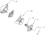
fig. 3 is an exploded view of the special-shaped snap shaft of the present invention;
fig. 4 is a perspective view of the inner corner block of the present invention;
FIG. 5 is an exploded view of the inside corner block of FIG. 4;
fig. 6 is a perspective view of the special-shaped buckle shaft connected with the outer corner block of the present invention;
FIG. 7 is an exploded view of FIG. 6;
wherein: 1, an outer corner block; 11 outer corner color blocks; 12 an outer corner block body; 2, a special-shaped buckle shaft; 21 a shaft rod; 22 a limiting block; 23, an axis; 24 circular grooves; 3, a central block; 4, inner corner blocks; 41 inner corner color blocks; 42 inner corner block body; 5, a sliding tongue base; 51 a tongue groove; 52 a tongue upright; 6 an axis magnet; 7 a bulk magnet; 8 axle center floating elasticity governing system.
Detailed Description
The technical solutions in the embodiments of the present invention will be described clearly and completely with reference to the accompanying drawings, and it is obvious that the described embodiments are only some embodiments of the present invention, not all embodiments.
It should be noted that, if directional indicators (such as … …, upper, lower, left, right, front, back, top, bottom, inner, outer, vertical, horizontal, longitudinal, counterclockwise, clockwise, circumferential, radial, axial) are involved in the embodiments of the present invention, the directional indicators are only used to explain the relative position, motion, etc. of the components in a specific posture (as shown in the drawings), and if the specific posture is changed, the directional indicators are changed accordingly.
As shown in fig. 1, the inside structure of the oblique magic cube is shown in fig. 2, the oblique magic cube with the magnetic attraction positioning mechanism comprises four outer corner blocks 1, an end-connected special-shaped buckle shaft 2 of the outer corner block 1, a center block 3 clamped with the outer corner block 1, and an inner corner block 4 located on one side of the end of a shaft lever 21 of the special-shaped buckle shaft 2 in the opposite direction and clamped with the center block 3, the bottoms of the outer corner block 1, the center block 3 and the inner corner block 4 are all provided with a sliding tongue base 5, the end of the shaft lever 21 is provided with a limiting block 22, the magnetic attraction positioning mechanism comprises an axis magnet 6 located on one side of the end of the shaft lever 22 in the opposite direction and located at an axis 23 of the special-shaped buckle shaft, and a block magnet 7 located at the bottom of the inner corner block 4, and the magnet block 7 is opposite to the axis magnet 6 when the oblique magic cube.
Specifically, as shown in fig. 3, the axis magnet 6 is cylindrical, four cylindrical grooves 24 for placing the axis magnet 6 are disposed at the axis of the special-shaped snap shaft 2, each cylindrical groove 24 is coaxial with one shaft rod 21, and the orientation of each cylindrical groove 24 is opposite to the extending direction of the coaxial shaft rod 21, so as to facilitate the fixing of the axis magnet 6, and meanwhile, the axis magnet 6 is coaxial with the corresponding shaft rod 21, so that the positioning is more accurate.
Specifically, as shown in fig. 4 to 5, the inner corner block includes an inner corner color block 41 and an inner corner block main body 42, a tongue groove 51 for placing the block magnet 7 is provided at the center of the lower end face of the tongue base 5 at the bottom of the inner corner block 4, a tongue upright post 52 is provided at the center of the upper end face of the tongue base 5, the tongue upright post 52 penetrates through the bottom wall of the inner corner block main body 42 and extends into the inner corner block main body 42, and the tongue upright post 52 extends into the inner corner block main body 42, so that when the inner corner block 4 is rotated by 120 degrees, a user can transfer torque as a moment arm by means of the tongue upright post 52, and the rotation is smoother.
Specifically, as shown in fig. 6 to 7, the outer corner block 1 includes an outer corner color block 11 and an outer corner main body 12, and the limiting block 22 at the end of the shaft rod 21 of the special-shaped snap shaft 2 is connected with the outer corner main body 12 through the axis floating elastic force adjusting system 8, so that a user can conveniently remove the outer corner block 1 and then take out the inner corner block 4 to float the elastic force adjusting system for replacement. For the specific structure and usage of the axle center floating spring force adjusting system 8, reference is made to the prior publication with publication number CN210384805U, and the description is not repeated here.
The above is only the preferred embodiment of the present invention, not limiting the scope of the present invention, all of which are under the concept of the present invention, the equivalent structure transformation made by the contents of the specification and the drawings is utilized, or the direct/indirect application in other related technical fields is included in the patent protection scope of the present invention.
Claims (4)
1. The utility model provides a be applied to axle center magnetism of oblique commentaries on classics magic cube and inhale positioning mechanism, the oblique commentaries on classics magic cube includes central axis body and block, its characterized in that: the magnetic attraction positioning mechanism comprises an axis magnet (6) arranged at the axis (23) of the central shaft body and a block magnet (7) arranged at the bottom of the block and corresponding to the axis magnet (6).
2. The axial magnetic attraction positioning mechanism applied to the oblique magic cube of claim 1, which is characterized in that: the block body comprises four outer corner blocks (1) and a central block (3) clamped with the outer corner blocks (1), and an inner corner block (4) which is positioned at one side of the outer corner block in the opposite direction and is clamped with the central block (3), the bottoms of the outer corner block (1), the central block (3) and the inner corner block (4) are all provided with a sliding tongue base (5), the central shaft body is a special-shaped buckle shaft (2), the special-shaped buckle shaft (2) comprises a shaft lever (21) and an axle center (23), the tail end of the shaft lever (21) is provided with a limiting block (22), the axis magnet (6) is arranged on one side of the tail end of the shaft lever (21) in the opposite direction and is positioned at the axis (23) of the special-shaped buckle shaft (2), the block magnet (7) is arranged at the bottom of the inner corner block (4), and the block magnet (7) is opposite to the axis magnet (6) when rotating 120 degrees along with the oblique magic cube.
3. The axial magnetic attraction positioning mechanism applied to the oblique magic cube of claim 2, which is characterized in that: the special-shaped buckle shaft is characterized in that the shaft center magnet (6) is cylindrical, four cylindrical grooves (24) used for placing the shaft center magnet (6) are formed in the shaft center (23) of the special-shaped buckle shaft (2), each cylindrical groove (24) is coaxial with one shaft rod (21), and the direction of each cylindrical groove (24) is opposite to the extending direction of the coaxial shaft rod (21).
4. The axial magnetic attraction positioning mechanism applied to the oblique magic cube of claim 3, which is characterized in that: interior angle piece (4) include interior angle color block (41) and interior angle piece main part (42), the lower terminal surface center department of tongue base (5) of interior angle piece main part (42) bottom sets up a tongue groove (51) that is used for placing block magnet (7), the up end center department of tongue base (5) sets up a tongue stand (52), tongue stand (52) run through the diapire of interior angle piece main part (42) and stretch into within interior angle piece main part (42).
Priority Applications (1)
| Application Number | Priority Date | Filing Date | Title |
|---|---|---|---|
| CN202020921870.3U CN212593917U (en) | 2020-05-27 | 2020-05-27 | Be applied to axle center magnetism of oblique commentaries on classics magic cube and inhale positioning mechanism |
Applications Claiming Priority (1)
| Application Number | Priority Date | Filing Date | Title |
|---|---|---|---|
| CN202020921870.3U CN212593917U (en) | 2020-05-27 | 2020-05-27 | Be applied to axle center magnetism of oblique commentaries on classics magic cube and inhale positioning mechanism |
Publications (1)
| Publication Number | Publication Date |
|---|---|
| CN212593917U true CN212593917U (en) | 2021-02-26 |
Family
ID=74751209
Family Applications (1)
| Application Number | Title | Priority Date | Filing Date |
|---|---|---|---|
| CN202020921870.3U Active CN212593917U (en) | 2020-05-27 | 2020-05-27 | Be applied to axle center magnetism of oblique commentaries on classics magic cube and inhale positioning mechanism |
Country Status (1)
| Country | Link |
|---|---|
| CN (1) | CN212593917U (en) |
Cited By (1)
| Publication number | Priority date | Publication date | Assignee | Title |
|---|---|---|---|---|
| CN111450518A (en) * | 2020-05-27 | 2020-07-28 | 广州淦源智能科技有限公司 | An axial magnetic attraction positioning mechanism applied to the oblique Rubik's cube |
-
2020
- 2020-05-27 CN CN202020921870.3U patent/CN212593917U/en active Active
Cited By (1)
| Publication number | Priority date | Publication date | Assignee | Title |
|---|---|---|---|---|
| CN111450518A (en) * | 2020-05-27 | 2020-07-28 | 广州淦源智能科技有限公司 | An axial magnetic attraction positioning mechanism applied to the oblique Rubik's cube |
Similar Documents
| Publication | Publication Date | Title |
|---|---|---|
| CN208255836U (en) | a remote control | |
| CN212593917U (en) | Be applied to axle center magnetism of oblique commentaries on classics magic cube and inhale positioning mechanism | |
| CN108568089A (en) | Magnetic force positions magic square | |
| CN111282259A (en) | Magnetic attraction positioning magic cube | |
| CN204699371U (en) | A kind of magnetic force storing magic square | |
| CN111450518A (en) | An axial magnetic attraction positioning mechanism applied to the oblique Rubik's cube | |
| CN206075630U (en) | Space Rotating converting means | |
| CN212235964U (en) | Magnetic attraction positioning magic cube | |
| JP2022159729A (en) | Magnetic force connection panel toy with spherical magnet embedded to corner of regular polygon and electrification thereof | |
| CN223184060U (en) | A gyroscope toy based on magnetic attraction | |
| CN208954470U (en) | A kind of mechanical drawing knowledge figure quick start teaching aid | |
| CN213904863U (en) | Display device for data rendering with good display effect | |
| CN205460920U (en) | Magnetic force concatenation toy stick | |
| US20250242231A1 (en) | Puzzle with magnetic system | |
| CN207657975U (en) | A kind of all-wheel steering mechanism of perambulator | |
| CN209378438U (en) | A kind of Puzzle provided with elements movable in relation to each other robot | |
| CN213432923U (en) | Novel rotary balance magic bead toy | |
| CN216771958U (en) | Miniature fluxgate sensor | |
| CN222357947U (en) | A multifunctional gyroscope | |
| CN213464511U (en) | Multi-angle exhibition show cupboard | |
| CN206243362U (en) | A kind of multiple degrees of freedom electrodynamic balance car handlebar | |
| CN202892891U (en) | Face changing toy | |
| CN207237240U (en) | A kind of new gyro magic square | |
| CN205734960U (en) | Robot head pitch system | |
| CN213298724U (en) | Built-in module slip table |
Legal Events
| Date | Code | Title | Description |
|---|---|---|---|
| GR01 | Patent grant | ||
| GR01 | Patent grant |