CN211674046U - Cleaning rollers that can be attached to cleaning robots and cleaning robots - Google Patents
Cleaning rollers that can be attached to cleaning robots and cleaning robots Download PDFInfo
- Publication number
- CN211674046U CN211674046U CN202020214922.3U CN202020214922U CN211674046U CN 211674046 U CN211674046 U CN 211674046U CN 202020214922 U CN202020214922 U CN 202020214922U CN 211674046 U CN211674046 U CN 211674046U
- Authority
- CN
- China
- Prior art keywords
- blade
- cleaning
- cleaning roller
- roller
- vanes
- Prior art date
- Legal status (The legal status is an assumption and is not a legal conclusion. Google has not performed a legal analysis and makes no representation as to the accuracy of the status listed.)
- Active
Links
Images


Classifications
-
- A—HUMAN NECESSITIES
- A47—FURNITURE; DOMESTIC ARTICLES OR APPLIANCES; COFFEE MILLS; SPICE MILLS; SUCTION CLEANERS IN GENERAL
- A47L—DOMESTIC WASHING OR CLEANING; SUCTION CLEANERS IN GENERAL
- A47L9/00—Details or accessories of suction cleaners, e.g. mechanical means for controlling the suction or for effecting pulsating action; Storing devices specially adapted to suction cleaners or parts thereof; Carrying-vehicles specially adapted for suction cleaners
- A47L9/02—Nozzles
- A47L9/04—Nozzles with driven brushes or agitators
- A47L9/0461—Dust-loosening tools, e.g. agitators, brushes
- A47L9/0466—Rotating tools
- A47L9/0477—Rolls
-
- A—HUMAN NECESSITIES
- A47—FURNITURE; DOMESTIC ARTICLES OR APPLIANCES; COFFEE MILLS; SPICE MILLS; SUCTION CLEANERS IN GENERAL
- A47L—DOMESTIC WASHING OR CLEANING; SUCTION CLEANERS IN GENERAL
- A47L11/00—Machines for cleaning floors, carpets, furniture, walls, or wall coverings
- A47L11/24—Floor-sweeping machines, motor-driven
-
- A—HUMAN NECESSITIES
- A47—FURNITURE; DOMESTIC ARTICLES OR APPLIANCES; COFFEE MILLS; SPICE MILLS; SUCTION CLEANERS IN GENERAL
- A47L—DOMESTIC WASHING OR CLEANING; SUCTION CLEANERS IN GENERAL
- A47L11/00—Machines for cleaning floors, carpets, furniture, walls, or wall coverings
- A47L11/40—Parts or details of machines not provided for in groups A47L11/02 - A47L11/38, or not restricted to one of these groups, e.g. handles, arrangements of switches, skirts, buffers, levers
- A47L11/4036—Parts or details of the surface treating tools
- A47L11/4041—Roll shaped surface treating tools
-
- A—HUMAN NECESSITIES
- A47—FURNITURE; DOMESTIC ARTICLES OR APPLIANCES; COFFEE MILLS; SPICE MILLS; SUCTION CLEANERS IN GENERAL
- A47L—DOMESTIC WASHING OR CLEANING; SUCTION CLEANERS IN GENERAL
- A47L11/00—Machines for cleaning floors, carpets, furniture, walls, or wall coverings
- A47L11/40—Parts or details of machines not provided for in groups A47L11/02 - A47L11/38, or not restricted to one of these groups, e.g. handles, arrangements of switches, skirts, buffers, levers
- A47L11/4063—Driving means; Transmission means therefor
- A47L11/4069—Driving or transmission means for the cleaning tools
-
- A—HUMAN NECESSITIES
- A47—FURNITURE; DOMESTIC ARTICLES OR APPLIANCES; COFFEE MILLS; SPICE MILLS; SUCTION CLEANERS IN GENERAL
- A47L—DOMESTIC WASHING OR CLEANING; SUCTION CLEANERS IN GENERAL
- A47L11/00—Machines for cleaning floors, carpets, furniture, walls, or wall coverings
- A47L11/40—Parts or details of machines not provided for in groups A47L11/02 - A47L11/38, or not restricted to one of these groups, e.g. handles, arrangements of switches, skirts, buffers, levers
- A47L11/4094—Accessories to be used in combination with conventional vacuum-cleaning devices
-
- A—HUMAN NECESSITIES
- A47—FURNITURE; DOMESTIC ARTICLES OR APPLIANCES; COFFEE MILLS; SPICE MILLS; SUCTION CLEANERS IN GENERAL
- A47L—DOMESTIC WASHING OR CLEANING; SUCTION CLEANERS IN GENERAL
- A47L9/00—Details or accessories of suction cleaners, e.g. mechanical means for controlling the suction or for effecting pulsating action; Storing devices specially adapted to suction cleaners or parts thereof; Carrying-vehicles specially adapted for suction cleaners
- A47L9/02—Nozzles
- A47L9/04—Nozzles with driven brushes or agitators
- A47L9/0405—Driving means for the brushes or agitators
- A47L9/0411—Driving means for the brushes or agitators driven by electric motor
-
- A—HUMAN NECESSITIES
- A47—FURNITURE; DOMESTIC ARTICLES OR APPLIANCES; COFFEE MILLS; SPICE MILLS; SUCTION CLEANERS IN GENERAL
- A47L—DOMESTIC WASHING OR CLEANING; SUCTION CLEANERS IN GENERAL
- A47L9/00—Details or accessories of suction cleaners, e.g. mechanical means for controlling the suction or for effecting pulsating action; Storing devices specially adapted to suction cleaners or parts thereof; Carrying-vehicles specially adapted for suction cleaners
- A47L9/28—Installation of the electric equipment, e.g. adaptation or attachment to the suction cleaner; Controlling suction cleaners by electric means
- A47L9/2836—Installation of the electric equipment, e.g. adaptation or attachment to the suction cleaner; Controlling suction cleaners by electric means characterised by the parts which are controlled
- A47L9/2852—Elements for displacement of the vacuum cleaner or the accessories therefor, e.g. wheels, casters or nozzles
-
- A—HUMAN NECESSITIES
- A47—FURNITURE; DOMESTIC ARTICLES OR APPLIANCES; COFFEE MILLS; SPICE MILLS; SUCTION CLEANERS IN GENERAL
- A47L—DOMESTIC WASHING OR CLEANING; SUCTION CLEANERS IN GENERAL
- A47L2201/00—Robotic cleaning machines, i.e. with automatic control of the travelling movement or the cleaning operation
- A47L2201/04—Automatic control of the travelling movement; Automatic obstacle detection
Landscapes
- Engineering & Computer Science (AREA)
- Mechanical Engineering (AREA)
- Nozzles For Electric Vacuum Cleaners (AREA)
- Electric Vacuum Cleaner (AREA)
- Cleaning Or Drying Semiconductors (AREA)
- Cleaning In General (AREA)
- Manipulator (AREA)
Abstract
Description
技术领域technical field
本申请涉及清洁辊,特别是用于清洁机器人的清洁辊。The present application relates to cleaning rollers, in particular cleaning rollers for cleaning robots.
背景技术Background technique
自主清洁机器人能够导航通过地板表面并避开障碍物,同时其可以清洁地板表面并操作其自带的可旋转部件摄取地板上的碎屑。当机器人移动通过地板表面时,机器人能够旋转可旋转部件,该可旋转部件吸引碎屑并把碎屑引导至机器人产生的真空气流。因此,可旋转部件和真空气流能够协同运作从而使机器人可以摄取碎屑。The autonomous cleaning robot is able to navigate through the floor surface and avoid obstacles, while it cleans the floor surface and operates its own rotatable parts to pick up debris on the floor. As the robot moves across the floor surface, the robot is able to rotate a rotatable member that attracts and directs the debris to the vacuum airflow generated by the robot. Thus, the rotatable parts and the vacuum flow can work together to allow the robot to ingest debris.
实用新型内容Utility model content
一种用于自主清洁机器人的清洁辊,其可在机器人的清洁操作期间旋转,从而在机器人移动通过地板表面时,清洁辊可以从地板表面吸引和拾取碎屑。清洁辊包括叶片,叶片被配置为在清洁辊旋转时扫过地板表面。叶片可包括多个相互连接的部分,所述相互连接的部分形成至少一个弯折。例如,叶片的第一部分能够在第一方向上延伸,叶片的附接到第一部分的第二部分能在不同于第一方向的第二方向上延伸。A cleaning roller for an autonomous cleaning robot that is rotatable during cleaning operations of the robot so that the cleaning roller can attract and pick up debris from the floor surface as the robot moves across the floor surface. The cleaning roller includes blades configured to sweep across the floor surface as the cleaning roller rotates. The blade may comprise a plurality of interconnected portions forming at least one bend. For example, a first portion of the vane can extend in a first direction and a second portion of the vane attached to the first portion can extend in a second direction different from the first direction.
本申请所述的清洁辊、清洁头和清洁机器人的优点可包括但不限于下文和本申请其他地方所述的那些优点。清洁辊的叶片的实施方式可以提高机器人的碎屑拾取能力。例如,当辊旋转并接合地板表面时,相对于沿径向轴线向外径向延伸并没有弯折的叶片,本申请叶片中的弯折可使叶片扫过地板表面的长度更大。叶片中的弯折还可以通过辊的旋转来抵消叶片的角偏转,从而在叶片扫过地板表面时允许叶片相对于地板表面保持方向。机器人可以包括多个叶片以进一步提高其碎屑拾取能力。在一些实施方式中,叶片的尖端部分可包括一些表面特征以提高叶片的碎屑拾取能力。沿尖端部分的凸出或凹入特征可允许叶片以更大的力接触地板表面,以搅动地板表面上的碎屑,从而更容易使用机器人的真空系统通过流动的空气把碎屑吸入机器人。叶片沿着清洁辊的螺旋路径会使被叶片清扫的碎屑移向辊的中心。这些螺旋路径因此可以允许碎片的机械搅拌与由机器人的真空组件产生的气流相配合,并且特别地,可以使碎片朝着辊的一个区域移动,其中在该区域中由真空组件产生的气流的力是最大的。Advantages of the cleaning rollers, cleaning heads, and cleaning robots described herein may include, but are not limited to, those described below and elsewhere in this application. The implementation of the blades of the cleaning roller can improve the debris pickup capability of the robot. For example, as the rollers rotate and engage the floor surface, the kinks in the vanes of the present application may allow the vanes to sweep a greater length across the floor surface relative to vanes extending radially outward along the radial axis without kinks. The kinks in the vanes can also counteract the angular deflection of the vanes by the rotation of the rollers, allowing the vanes to maintain orientation relative to the floor surface as the vanes sweep across the floor surface. The robot can include multiple blades to further improve its debris pickup capabilities. In some embodiments, the tip portion of the blade may include surface features to improve the debris pickup capability of the blade. A convex or concave feature along the tip portion may allow the blades to contact the floor surface with greater force to agitate debris on the floor surface, making it easier to draw debris into the robot by flowing air using the robot's vacuum system. The helical path of the vanes along the cleaning roller moves debris swept by the vanes toward the center of the roller. These helical paths may thus allow mechanical agitation of the chips to be coordinated with the air flow generated by the vacuum assembly of the robot and, in particular, may move the chips towards an area of the rollers in which the force of the air flow generated by the vacuum assembly is present is the largest.
辊可进一步被配置为提高机器人的机动性。例如,辊可以关于辊的中心轴向平面对称。当机器人沿着地板表面移动并且当辊接触地板表面时,这种对称性可以减小辊在机器人上产生侧向力的趋势。因此,当机器人沿向前驱动方向移动时,辊不太可能使机器人漂移,例如向左或向右漂移。辊的叶片也可以被配置为提高机器人的机动性。叶片可以具有足够的柔韧性,以减小叶片接触地板表面时叶片影响机器人的运动方向的可能性。在一些实施方式中,辊可以包括使辊能够帮助机器人移动通过地板表面上障碍物的特征。例如,辊可包括自清洁辊延伸的凸块,该凸块与地板表面上的障碍物接合。凸块可以足够坚硬,以允许辊与障碍物接合并将机器人提升到障碍物上方,从而使机器人能够移动通过障碍物。The rollers may be further configured to improve the maneuverability of the robot. For example, the rolls may be plane symmetrical about the central axial plane of the rolls. This symmetry can reduce the tendency of the rollers to generate lateral forces on the robot as the robot moves along the floor surface and when the rollers contact the floor surface. Therefore, the rollers are less likely to drift the robot, such as left or right, when the robot is moving in the forward drive direction. The blades of the rollers can also be configured to improve the manoeuvrability of the robot. The blades may be sufficiently flexible to reduce the possibility of the blades affecting the direction of motion of the robot when the blades contact the floor surface. In some embodiments, the rollers may include features that enable the rollers to assist the robot in moving through obstacles on the floor surface. For example, the rollers may include tabs extending from the cleaning rollers that engage obstacles on the floor surface. The bumps can be rigid enough to allow the rollers to engage the obstacle and lift the robot over the obstacle, allowing the robot to move through the obstacle.
辊还可包括一些特征,这些特征在辊接触地板表面时减少由辊产生的噪声量。叶片可以沿沿着清洁辊的表面的螺旋路径延伸,这种构造可以减少由清洁辊产生的噪声量。在一些实施方式中,叶片的第一部分和第二部分被成形以减小叶片的刚度并因此减轻噪声。辊还可包括沿着叶片的一个或多个开口,这些开口可进一步用于减轻噪声。例如,辊可包括沿着叶片的一个或多个开口,以减小辊在沿辊的各个位置处(例如,在辊的中心处、在沿辊的四分点处或在其他位置处)的刚度。辊刚度的降低可进一步降低辊接触物体(比如地板表面或碎屑)时产生的噪声。The rollers may also include features that reduce the amount of noise generated by the rollers when they contact the floor surface. The vanes may extend along a helical path along the surface of the cleaning roller, a configuration that reduces the amount of noise generated by the cleaning roller. In some embodiments, the first and second portions of the blade are shaped to reduce the stiffness of the blade and thus reduce noise. The rollers may also include one or more openings along the blades, which openings may further serve to mitigate noise. For example, the rollers may include one or more openings along the vanes to reduce the rollers at various locations along the rollers (eg, at the center of the rollers, at quarter points along the rollers, or at other locations) stiffness. The reduction in roll stiffness can further reduce the noise generated when the roll contacts objects such as floor surfaces or debris.
辊可包括减少叶片易磨损性的特征。例如,辊的叶片与叶片所连接的伸长部件之间的交界处可降低叶片的易磨损性。例如,叶片可从伸长部件切向延伸,从而减小了叶片附接到伸长部件的位置附近应力集中的可能性。The rollers may include features that reduce the susceptibility of the blades to wear. For example, the interface between the vanes of the roller and the elongated member to which the vanes are attached may reduce the susceptibility of the vanes to wear. For example, the vanes may extend tangentially from the elongated member, thereby reducing the likelihood of stress concentrations near where the vanes are attached to the elongated member.
一方面,本申请描述了一种可安装到清洁机器人的清洁辊。清洁辊包括沿清洁辊的纵向轴线延伸的伸长部件和从伸长部件向外延伸的叶片。叶片包括附接到伸长部件的第一叶片部分和附接到第一叶片部分的第二叶片部分。第一叶片部分在与清洁辊的径向轴线相交的位置处从伸长部件延伸。第一叶片部分沿第一轴线延伸并且沿切线方向远离径向轴线,该第一轴线相对于径向轴线成角度。第二叶片部分沿第二轴线延伸,该第二轴线相对于第一轴线成角度。第一轴线和径向轴线之间的第一角度大于第二轴线和径向轴线之间的第二角度。In one aspect, the present application describes a cleaning roller mountable to a cleaning robot. The cleaning roller includes an elongated member extending along a longitudinal axis of the cleaning roller and vanes extending outwardly from the elongated member. The blade includes a first blade portion attached to the elongated member and a second blade portion attached to the first blade portion. The first blade portion extends from the elongated member at a location intersecting the radial axis of the cleaning roller. The first blade portion extends along a first axis and is tangentially away from a radial axis, the first axis being angled with respect to the radial axis. The second blade portion extends along a second axis that is angled relative to the first axis. The first angle between the first axis and the radial axis is greater than the second angle between the second axis and the radial axis.
另一方面,本申请描述了一种用于真空清洁器的清洁头。清洁头包括导管和被配置为将碎屑扫入导管的清洁辊。清洁辊包括沿清洁辊的纵向轴线延伸的伸长部件和从伸长部件向外延伸的叶片。叶片包括附接到伸长部件的第一叶片部分和附接到第一叶片部分的第二叶片部分。第一叶片部分在与清洁辊的径向轴线相交的位置处从伸长部件延伸。第一叶片部分沿第一轴线延伸并且沿切线方向远离径向轴线,该第一轴线相对于径向轴线成角度。第二叶片部分沿第二轴线延伸,该第二轴线相对于第一轴线成角度。第一轴线和径向轴线之间的第一角度大于第二轴线和径向轴线之间的第二角度。In another aspect, the present application describes a cleaning head for a vacuum cleaner. The cleaning head includes a conduit and a cleaning roller configured to sweep debris into the conduit. The cleaning roller includes an elongated member extending along a longitudinal axis of the cleaning roller and vanes extending outwardly from the elongated member. The blade includes a first blade portion attached to the elongated member and a second blade portion attached to the first blade portion. The first blade portion extends from the elongated member at a location intersecting the radial axis of the cleaning roller. The first blade portion extends along a first axis and is tangentially away from a radial axis, the first axis being angled with respect to the radial axis. The second blade portion extends along a second axis that is angled relative to the first axis. The first angle between the first axis and the radial axis is greater than the second angle between the second axis and the radial axis.
另一方面,清洁机器人包括:驱动系统,其使机器人在地板表面上移动;以及清洁辊,其可安装至清洁机器人。清洁辊可在第一旋转方向上绕清洁辊的纵向轴线旋转。清洁辊包括沿清洁辊的纵向轴线延伸的伸长部件和从伸长部件向外延伸的叶片。叶片包括附接到伸长部件的第一叶片部分和附接到第一叶片部分的第二叶片部分。第一叶片部分在与清洁辊的径向轴线相交的位置处从伸长部件延伸。第一叶片部分沿第一轴线延伸并且沿切线方向远离径向轴线,该第一轴线相对于径向轴线成角度。第二叶片部分沿第二轴线延伸,该第二轴线相对于第一轴线成角度。第一轴线和径向轴线之间的第一角度大于第二轴线和径向轴线之间的第二角度。On the other hand, the cleaning robot includes: a drive system that moves the robot on a floor surface; and a cleaning roller that can be mounted to the cleaning robot. The cleaning roller is rotatable about a longitudinal axis of the cleaning roller in a first rotational direction. The cleaning roller includes an elongated member extending along a longitudinal axis of the cleaning roller and vanes extending outwardly from the elongated member. The blade includes a first blade portion attached to the elongated member and a second blade portion attached to the first blade portion. The first blade portion extends from the elongated member at a location intersecting the radial axis of the cleaning roller. The first blade portion extends along a first axis and is tangentially away from a radial axis, the first axis being angled with respect to the radial axis. The second blade portion extends along a second axis that is angled relative to the first axis. The first angle between the first axis and the radial axis is greater than the second angle between the second axis and the radial axis.
在一些实施方式中,叶片可包括第一叶片,并且清洁辊可包括多个叶片,所述多个叶片至少包括第一叶片和第二叶片。第二叶片可以从壳体向外延伸远离清洁辊的纵向轴线,并且在切线方向上自第一叶片偏移。In some embodiments, the vanes may include a first vane, and the cleaning roller may include a plurality of vanes including at least a first vane and a second vane. The second vane may extend outwardly from the housing away from the longitudinal axis of the cleaning roller and be tangentially offset from the first vane.
在一些实施方式中,清洁辊可包括多个叶片,所述多个叶片包括第一叶片和第二叶片。多个叶片中的每个叶片可关于一个平面对称。该平面可以位于清洁辊的中心并且垂直于清洁辊的纵向轴线。在进一步的实施方式中,径向轴线可以是第一径向轴线,并且第二叶片可以在与清洁辊的第二径向轴线相交的位置处附接到壳体。第一径向轴线和第二径向轴线可形成30度到90度的角度。In some embodiments, the cleaning roller may include a plurality of blades including a first blade and a second blade. Each of the plurality of vanes may be symmetrical about a plane. The plane may be centered on the cleaning roll and perpendicular to the longitudinal axis of the cleaning roll. In further embodiments, the radial axis may be the first radial axis, and the second vane may be attached to the housing at a location intersecting the second radial axis of the cleaning roller. The first radial axis and the second radial axis may form an angle of 30 degrees to 90 degrees.
在一些实施方式中,伸长部件可以是圆柱形的。第一轴线可以从伸长部件的圆周切向延伸。In some embodiments, the elongated member may be cylindrical. The first axis may extend tangentially from the circumference of the elongated member.
在一些实施方式中,切线方向可以是第二切线方向。第二叶片部分可包括面向第一切线方向的第一表面和面向第二切线方向的第二表面。第一和第二表面可以位于第二叶片部分的尖端和第一叶片部分之间,并且第一表面可以是弯曲的。在进一步的实施方式中,第一表面可以是凹面的。在进一步的实施方式中,第一表面可以是凸面的。In some embodiments, the tangential direction may be the second tangential direction. The second blade portion may include a first surface facing the first tangential direction and a second surface facing the second tangential direction. The first and second surfaces may be located between the tip of the second blade portion and the first blade portion, and the first surface may be curved. In further embodiments, the first surface may be concave. In further embodiments, the first surface may be convex.
在一些实施方式中,径向轴线可以是第一径向轴线,并且第二叶片部分可以延伸穿过清洁辊的第二径向轴线。第二轴线可与第二径向轴线形成不大于5度的角度。In some embodiments, the radial axis may be the first radial axis and the second vane portion may extend through the second radial axis of the cleaning roller. The second axis may form an angle of no more than 5 degrees with the second radial axis.
在一些实施方式中,叶片的一区段可以沿沿着伸长部件的螺旋路径延伸。在进一步的实施方式中,螺旋路径可以是第一螺旋路径,并且叶片的区段可以是叶片的第一区段。叶片的第二区段可沿沿着伸长部件的第二螺旋路径延伸。在进一步的实施方式中,第一螺旋路径可在清洁辊的切线方向上沿着伸长部件从第一螺旋路径的第一端延伸到第一螺旋路径的第二端。第一螺旋路径的第一端可位于清洁辊的第一纵向端部附近,并且第一螺旋路径的第二端可以位于清洁辊的中心附近。第二螺旋路径可以在清洁辊的切线方向上沿着伸长部件从第二螺旋路径的第一端延伸到第二螺旋路径的第二端。第二螺旋路径的第一端可以位于清洁辊的第二纵向端部附近,并且第二螺旋路径的第二端可以位于清洁辊的中心附近。在进一步的实施方式中,第一螺旋路径可以关于一个平面与第二螺旋路径相对称。该平面可以位于清洁辊的中心并且垂直于清洁辊的纵向轴线。在进一步的实施方式中,螺旋路径的螺距可以是300到900毫米。In some embodiments, a section of the blade may extend along a helical path along the elongated member. In further embodiments, the helical path may be a first helical path and the section of the blade may be the first section of the blade. The second section of the blade may extend along a second helical path along the elongated member. In further embodiments, the first helical path may extend along the elongated member in a tangential direction of the cleaning roller from a first end of the first helical path to a second end of the first helical path. The first end of the first helical path may be located near the first longitudinal end of the cleaning roller, and the second end of the first helical path may be located near the center of the cleaning roller. The second helical path may extend along the elongated member in a tangential direction of the cleaning roller from a first end of the second helical path to a second end of the second helical path. The first end of the second helical path may be located near the second longitudinal end of the cleaning roller, and the second end of the second helical path may be located near the center of the cleaning roller. In further embodiments, the first helical path may be symmetrical about a plane to the second helical path. The plane may be centered on the cleaning roll and perpendicular to the longitudinal axis of the cleaning roll. In further embodiments, the pitch of the helical path may be 300 to 900 millimeters.
在一些实施方式中,清洁辊可进一步包括从伸长部件向外延伸远离纵向轴线的凸块。叶片的外部尖端相对于伸长部件的高度可以大于凸块的外部尖端相对于壳体的高度。在进一步的实施方式中,凸块的最大厚度为8毫米至18毫米。在进一步的实施方式中,凸块可以从伸长部件到凸块的外部尖端逐渐变细。在进一步的实施方式中,凸块可以是第一凸块,并且清洁辊还可以包括第二凸块,该第二凸块从伸长部件向外延伸远离纵向轴线。叶片可位于第一凸块和第二凸块之间。在进一步的实施方式中,凸块的外尖端相对于伸长部件的高度可以是0.25至2.0厘米。In some embodiments, the cleaning roller may further include a tab extending outwardly from the elongate member away from the longitudinal axis. The height of the outer tips of the vanes relative to the elongated member may be greater than the height of the outer tips of the lugs relative to the housing. In further embodiments, the bumps have a maximum thickness of 8 mm to 18 mm. In further embodiments, the bumps may taper from the elongate member to the outer tips of the bumps. In further embodiments, the bumps may be first bumps, and the cleaning roller may further include second bumps extending outwardly from the elongate member away from the longitudinal axis. The vane may be located between the first bump and the second bump. In further embodiments, the height of the outer tips of the bumps relative to the elongated member may be 0.25 to 2.0 centimeters.
在一些实施方式中,叶片可以包括沿着清洁辊的中央部分延伸的开口。开口仅可部分地通过叶片并远离伸长部件朝向叶片的外尖端延伸。在进一步的实施方式中,开口可以从伸长部件朝向叶片的外尖端延伸。在进一步的实施方式中,开口可以朝向叶片的外部尖端逐渐变细。在进一步的实施方式中,开口的最大宽度为2毫米至8毫米。在进一步的实施方式中,第一叶片部分可包括第一区段和第二区段,第一区段从清洁辊的第一纵向端部朝向清洁辊的中心部分延伸,第二区段从清洁辊的第二纵向端部朝向清洁辊的中心部分延伸。第一叶片部分的第一区段可以通过开口与第一叶片部分的第二区段分开,并且第二叶片部分可以沿着叶片从清洁辊的第一纵向端部向清洁辊的第二纵向端部连续地延伸。In some embodiments, the vanes may include openings extending along a central portion of the cleaning roller. The opening can only extend partially through the blade and away from the elongated member towards the outer tip of the blade. In further embodiments, the opening may extend from the elongate member towards the outer tip of the blade. In further embodiments, the opening may taper towards the outer tip of the blade. In a further embodiment, the maximum width of the opening is 2 millimeters to 8 millimeters. In a further embodiment, the first blade portion may include a first section extending from the first longitudinal end of the cleaning roll towards a central portion of the cleaning roll and a second section extending from the cleaning roll The second longitudinal end of the roller extends towards the central portion of the cleaning roller. The first section of the first blade portion may be separated from the second section of the first blade portion by an opening, and the second blade portion may be along the blade from the first longitudinal end of the cleaning roller to the second longitudinal end of the cleaning roller The part extends continuously.
在一些实施方式中,叶片可以是第一叶片,并且清洁辊可以进一步包括第二叶片。第一叶片可包括靠近清洁辊的第一纵向端的第一纵向端和靠近清洁辊中心的第二纵向端。第二叶片可包括靠近清洁辊的第二纵向端的第一纵向端和靠近清洁辊中心的第二纵向端。第一叶片的第二纵向端可以与第二叶片的第二纵向端分离。In some embodiments, the blade may be a first blade, and the cleaning roller may further include a second blade. The first vane may include a first longitudinal end proximate the first longitudinal end of the cleaning roll and a second longitudinal end proximate the center of the cleaning roll. The second vane may include a first longitudinal end proximate the second longitudinal end of the cleaning roll and a second longitudinal end proximate the center of the cleaning roll. The second longitudinal end of the first vane may be separated from the second longitudinal end of the second vane.
在一些实施方式中,清洁辊的外径在清洁辊的整个长度上可以是均匀的。外径可以至少部分地由叶片限定。In some embodiments, the outer diameter of the cleaning roll may be uniform over the entire length of the cleaning roll. The outer diameter may be at least partially defined by the vanes.
在一些实施方式中,伸长部件可以在清洁辊的整个长度上是圆柱形的。In some embodiments, the elongated member may be cylindrical over the entire length of the cleaning roll.
在一些实施方式中,第一叶片部分可包括附接到伸长部件的第一端和附接到第二叶片部分的第二端。第一叶片部分的第一端与清洁辊的纵向轴线之间的第一径向距离可以是第一叶片部分的第二端与清洁辊的纵向轴线之间的第二径向距离的50%至90%。In some embodiments, the first blade portion may include a first end attached to the elongate member and a second end attached to the second blade portion. The first radial distance between the first end of the first blade portion and the longitudinal axis of the cleaning roller may be 50% to 50% of the second radial distance between the second end of the first blade portion and the longitudinal axis of the cleaning roller. 90%.
在一些实施方式中,从第二叶片部分的第一端到第二叶片部分的第二端的长度可以是从第一叶片部分的第一端到第一叶片的第二端的长度的25%至75%。In some embodiments, the length from the first end of the second blade portion to the second end of the second blade portion may be 25% to 75% of the length from the first end of the first blade portion to the second end of the first blade %.
在一些实施方式中,从第一叶片部分的第一端到第一叶片部分的第二端的第一长度可以是0.5到3厘米。从第二叶片部分的第一端到第二叶片部分的第二端的第二长度可以是0.2到1.5厘米。In some embodiments, the first length from the first end of the first blade portion to the second end of the first blade portion may be 0.5 to 3 centimeters. The second length from the first end of the second blade portion to the second end of the second blade portion may be 0.2 to 1.5 centimeters.
在一些实施方式中,第一叶片部分的厚度可以是0.5到4毫米。In some embodiments, the thickness of the first blade portion may be 0.5 to 4 millimeters.
在一些实施方式中,第二叶片部分的最大厚度可以是2到5毫米。In some embodiments, the maximum thickness of the second blade portion may be 2 to 5 millimeters.
在一些实施方式中,清洁辊的总直径可以是30至90毫米,并且清洁辊的总长度为10至50厘米。In some embodiments, the overall diameter of the cleaning roll may be 30 to 90 millimeters, and the overall length of the cleaning roll may be 10 to 50 centimeters.
在一些实施方式中,叶片还可包括附接到第二叶片部分的第三部分。叶片的第三部分可沿着第三轴线延伸,第三轴线相对于第二轴线成角度。第三轴线和径向轴线之间的第三角度可以小于第二轴线和径向轴线之间的第二角度。在进一步的实施方式中,叶片的第三部分可以包括叶片的尖端部分。In some embodiments, the blade may further include a third portion attached to the second blade portion. The third portion of the vane may extend along a third axis that is angled relative to the second axis. The third angle between the third axis and the radial axis may be smaller than the second angle between the second axis and the radial axis. In further embodiments, the third portion of the vane may comprise a tip portion of the vane.
另一方面,本申请描述了一种可安装到清洁机器人的清洁辊。清洁辊包括沿着清洁辊的纵向轴线延伸的伸长部件和附接到该伸长部件的叶片。叶片包括第一叶片部分、第二叶片部分和弯折,第一叶片部分从附接到伸长部件的第一端延伸到第二端,第二叶片部分从附接到第一叶片部分的第二端的第一端延伸到包括叶片尖端部分的第二端,第一叶片部分的第二端在弯折处附接到第二叶片部分的第一端。In another aspect, the present application describes a cleaning roller mountable to a cleaning robot. The cleaning roller includes an elongated member extending along a longitudinal axis of the cleaning roller and vanes attached to the elongated member. The vane includes a first vane portion extending from a first end attached to the elongated member to a second end, a second vane portion extending from a second vane portion attached to the first vane portion, and a bend. The first end of the two ends extends to include a second end of the blade tip portion, the second end of the first blade portion being attached to the first end of the second blade portion at a bend.
在一些实施方式中,第一叶片部分的第一端可以沿着与清洁辊的第一径向轴线相交的位置附接到伸长部件,并且叶片的尖端部分可以沿着清洁辊的第二径向轴线布置。在进一步的实施方式中,第一径向轴线和第二径向轴线之间的角度可以是20度至70度。在进一步的实施方式中,第一叶片部分可以沿着第一轴线延伸,第二叶片部分可以沿着第二轴线延伸。第一轴线和第一径向轴线之间的角度可以大于第二轴线和第一径向轴线之间的角度。在进一步的实施方式中,第一轴线和第二轴线之间的角度可以是90度到170度。In some embodiments, the first end of the first blade portion may be attached to the elongated member along a location intersecting the first radial axis of the cleaning roller, and the tip portion of the blade may be along the second diameter of the cleaning roller Arrange to the axis. In further embodiments, the angle between the first radial axis and the second radial axis may be 20 degrees to 70 degrees. In further embodiments, the first blade portion may extend along a first axis and the second blade portion may extend along a second axis. The angle between the first axis and the first radial axis may be greater than the angle between the second axis and the first radial axis. In further embodiments, the angle between the first axis and the second axis may be 90 degrees to 170 degrees.
在一些实施方式中,第二叶片部分的长度可以是第一叶片部分长度的25%至75%。In some embodiments, the length of the second blade portion may be 25% to 75% of the length of the first blade portion.
在一些实施方式中,第二叶片部分可包括面向第一切线方向的第一表面和面向第二切线方向的第二表面。第一表面可以包括凸出部。在进一步的实施方式中,第二叶片部分的第一表面的凸出部可以连接至第一叶片部分,并且第二叶片部分的第一表面还可以包括连接至凸出部的凹入部。在进一步的实施方式中,第一叶片部分可包括面向第一切线方向的第一表面和面向第二切线方向的第二表面。第一叶片部分的第一表面和第二表面可以彼此平行。In some embodiments, the second blade portion may include a first surface facing the first tangential direction and a second surface facing the second tangential direction. The first surface may include protrusions. In further embodiments, the protrusions of the first surface of the second blade portion may be connected to the first blade portion, and the first surface of the second blade portion may further comprise recesses connected to the protrusions. In further embodiments, the first blade portion may comprise a first surface facing the first tangential direction and a second surface facing the second tangential direction. The first surface and the second surface of the first blade portion may be parallel to each other.
在一些实施方式中,尖端部分可以是勺形的。In some embodiments, the tip portion may be spoon-shaped.
在一些实施方式中,第一叶片部分的最大厚度可以是1至4毫米。在进一步的实施方式中,第二叶片部分的最大厚度可以比第一叶片部分的最大厚度大10%至75%。In some embodiments, the maximum thickness of the first blade portion may be 1 to 4 millimeters. In further embodiments, the maximum thickness of the second blade portion may be 10% to 75% greater than the maximum thickness of the first blade portion.
在一些实施方式中,叶片相对于伸长部件的高度可以是0.5至2.5厘米。In some embodiments, the height of the vanes relative to the elongated member may be 0.5 to 2.5 centimeters.
另一方面,本申请描述了一种可安装到清洁机器人的清洁辊。清洁辊包括沿着清洁辊的纵向轴线延伸的伸长部件和附接到该伸长部件的叶片。叶片包括第一弯折和第二弯折。第一弯折位于伸长部件与第二弯折之间,第二弯折位于第一弯折与叶片的顶端部分之间。In another aspect, the present application describes a cleaning roller mountable to a cleaning robot. The cleaning roller includes an elongated member extending along a longitudinal axis of the cleaning roller and vanes attached to the elongated member. The blade includes a first bend and a second bend. The first bend is between the elongated member and the second bend, and the second bend is between the first bend and the tip portion of the blade.
在一些实施方式中,叶片可包括从伸长部件向外延伸的第一叶片部分和从第一叶片部分向外延伸的第二叶片部分。第一叶片部分可以在第一弯折处附接到第二叶片部分。在进一步的实施方式中,叶片可以包括第三叶片部分,该第三叶片部分从第二叶片部分向外延伸并且终止于叶片的尖端部分。第二叶片部分可以在第二弯折处附接到第三叶片部分。在进一步的实施方式中,第二叶片部分的长度可以是第一叶片部分长度的15%至35%。在进一步的实施方式中,第三叶片部分的长度可以是第一叶片部分的长度的10%至30%。在进一步的实施方式中,叶片可以在与清洁辊的径向轴线相交的位置处附接到伸长部件,第一叶片部分可以沿着第一轴线延伸,并且第二叶片部分可以沿着第二轴线延伸。第一轴线和径向轴线之间的角度可以大于第二轴线和径向轴线之间的角度。在进一步的实施方式中,第三叶片部分可以沿着第三轴线延伸,并且第二轴线和径向轴线之间的角度可以小于第三轴线和径向轴线之间的角度。在进一步的实施方式中,第一轴线和第二轴线之间的角度可以是90度到170度。在进一步的实施方式中,第二轴线和第三轴线之间的角度可以是90度至170度。在进一步的实施方式中,第三轴线与第一轴线之间的角度可以不大于5至15度。In some embodiments, the vane may include a first vane portion extending outwardly from the elongate member and a second vane portion extending outwardly from the first vane portion. The first blade portion may be attached to the second blade portion at the first bend. In further embodiments, the vane may include a third vane portion extending outwardly from the second vane portion and terminating at a tip portion of the vane. The second blade portion may be attached to the third blade portion at a second bend. In further embodiments, the length of the second blade portion may be 15% to 35% of the length of the first blade portion. In further embodiments, the length of the third blade portion may be 10% to 30% of the length of the first blade portion. In further embodiments, the vanes may be attached to the elongate member at locations intersecting the radial axis of the cleaning roller, the first vane portion may extend along the first axis, and the second vane portion may extend along the second axis extension. The angle between the first axis and the radial axis may be greater than the angle between the second axis and the radial axis. In further embodiments, the third vane portion may extend along the third axis, and the angle between the second axis and the radial axis may be smaller than the angle between the third axis and the radial axis. In further embodiments, the angle between the first axis and the second axis may be 90 degrees to 170 degrees. In further embodiments, the angle between the second axis and the third axis may be 90 degrees to 170 degrees. In further embodiments, the angle between the third axis and the first axis may be no greater than 5 to 15 degrees.
另一方面,本申请描述了一种可安装到清洁机器人的清洁辊。清洁辊包括沿着清洁辊的纵向轴线延伸的伸长部件和附接到该伸长部件的叶片。叶片沿沿着伸长部件纵向延伸的螺旋路径延伸。叶片包括沿清洁辊的中心部分延伸的开口。In another aspect, the present application describes a cleaning roller mountable to a cleaning robot. The cleaning roller includes an elongated member extending along a longitudinal axis of the cleaning roller and vanes attached to the elongated member. The vanes extend along a helical path extending longitudinally along the elongated member. The blades include openings extending along the central portion of the cleaning roller.
在一些实施方式中,开口可以包括狭缝。In some embodiments, the openings may comprise slits.
在一些实施方式中,开口可远离伸长部件朝向叶片的外尖端延伸。开口可以朝着叶片的外尖端逐渐变细。在进一步的实施方式中,开口的最大宽度为2毫米至8毫米。在进一步的实施方式中,开口可以关于清洁辊的中心横截面对称。In some embodiments, the opening may extend away from the elongate member towards the outer tip of the blade. The opening may taper towards the outer tip of the blade. In a further embodiment, the maximum width of the opening is 2 millimeters to 8 millimeters. In further embodiments, the openings may be symmetrical about the central cross-section of the cleaning roller.
在一些实施方式中,开口可以仅部分地通过叶片并远离伸长部件朝向叶片的外尖端延伸。在进一步的实施方式中,开口可以从伸长部件朝向叶片的外尖端延伸。In some embodiments, the opening may extend only partially through the blade and away from the elongate member towards the outer tip of the blade. In further embodiments, the opening may extend from the elongate member towards the outer tip of the blade.
在一些实施方式中,叶片可包括第一叶片部分、第二叶片部分和弯折,其中第一叶片部分附接到第二叶片部分。开口可以延伸通过第一叶片部分的整个长度。在进一步的实施方式中,开口的远端终止点可以与第一叶片部分附接到第二叶片部分的位置重合。在进一步的实施方式中,叶片可以沿着伸长部件的整个长度延伸。在进一步的实施方式中,第一叶片部分可包括第一区段和第二区段。第一区段可以通过开口与第二区段分开。在进一步的实施方式中,第二叶片部分可以沿着伸长部件的整个长度连续地延伸。In some embodiments, the vane may include a first vane portion, a second vane portion, and a bend, wherein the first vane portion is attached to the second vane portion. The opening may extend through the entire length of the first blade portion. In further embodiments, the distal end point of the opening may coincide with where the first blade portion is attached to the second blade portion. In further embodiments, the vanes may extend along the entire length of the elongate member. In further embodiments, the first blade portion may include a first section and a second section. The first section may be separated from the second section by an opening. In further embodiments, the second blade portion may extend continuously along the entire length of the elongate member.
另一方面,本申请描述了一种可安装到清洁机器人的清洁辊。清洁辊包括沿着清洁辊的纵向轴线延伸的伸长部件、附接到伸长部件的叶片以及附接到伸长部件的凸块。凸块从伸长部件向外延伸。凸块在伸长部件之上的高度小于叶片在伸长部件之上的高度。In another aspect, the present application describes a cleaning roller mountable to a cleaning robot. The cleaning roller includes an elongated member extending along a longitudinal axis of the cleaning roller, vanes attached to the elongated member, and tabs attached to the elongated member. The tabs extend outwardly from the elongated member. The height of the lugs above the elongated member is less than the height of the vanes above the elongated member.
在一些实施方式中,叶片可以是可弯曲的,并且凸块可以是刚性突起。In some embodiments, the vanes may be bendable and the bumps may be rigid protrusions.
在一些实施方式中,凸块可以从伸长部件到凸块的尖端部分逐渐变细。In some embodiments, the bump may taper from the elongate member to the tip portion of the bump.
在一些实施方式中,凸块可以是自伸长部件的大致三角形的突起。In some embodiments, the bumps may be generally triangular-shaped protrusions of the self-elongating member.
在一些实施方式中,凸块在伸长部件之上的高度为0.25至2厘米,在进一步的实施方式中,叶片的高度可以比凸块的高度大25%至100%。In some embodiments, the height of the lugs above the elongated member is 0.25 to 2 centimeters, and in further embodiments, the height of the vanes may be 25% to 100% greater than the height of the lugs.
在一些实施方式中,凸块可以包括面对清洁辊的第一切线方向的第一表面和面对清洁辊的第二切线方向的第二表面。第一表面的长度可以大于第二表面的长度。在进一步的实施方式中,第一表面的长度可以是第二表面的长度的1.5至2.5倍。In some embodiments, the bumps may include a first surface facing a first tangential direction of the cleaning roller and a second surface facing a second tangential direction of the cleaning roller. The length of the first surface may be greater than the length of the second surface. In further embodiments, the length of the first surface may be 1.5 to 2.5 times the length of the second surface.
在一些实施方式中,凸块的最大厚度是8到18毫米。In some embodiments, the bumps have a maximum thickness of 8 to 18 millimeters.
在一些实施方式中,叶片可以是附接到伸长部件的第一叶片,并且清洁辊可以进一步包括第二叶片。凸块可位于第一叶片和第二叶片之间。In some embodiments, the blade may be a first blade attached to the elongated member, and the cleaning roller may further include a second blade. The tabs may be located between the first vane and the second vane.
在一些实施方式中,凸块可以沿着伸长部件、沿沿着伸长部件的螺旋路径在纵向和圆周方向上延伸。In some embodiments, the bumps may extend longitudinally and circumferentially along the elongated member, along a helical path along the elongated member.
另一方面,本申请描述了一种可安装到清洁机器人的清洁辊。清洁辊包括沿着清洁辊的纵向轴线延伸的伸长部件、附接到伸长部件的叶片以及附接到伸长部件的凸块。凸块可以从伸长部件向外延伸,并且可以包括用于接收硬毛刷的开口。In another aspect, the present application describes a cleaning roller mountable to a cleaning robot. The cleaning roller includes an elongated member extending along a longitudinal axis of the cleaning roller, vanes attached to the elongated member, and tabs attached to the elongated member. The tabs may extend outwardly from the elongate member and may include openings for receiving the bristle brushes.
在一些实施方式中,开口可以从凸块的表面径向向内延伸。In some embodiments, the openings may extend radially inward from the surfaces of the bumps.
在一些实施方式中,开口可以包括矩形部分。In some embodiments, the opening may comprise a rectangular portion.
在一些实施方式中,叶片的第一部分可以沿切线方向向外延伸,并且开口可以面向切线方向。In some embodiments, the first portion of the vane may extend outward in a tangential direction, and the opening may face in a tangential direction.
在一些实施方式中,凸块相对于伸长部件的高度可以小于叶片相对于伸长部件的高度。In some embodiments, the height of the bump relative to the elongated member may be less than the height of the blade relative to the elongated member.
在一些实施方式中,开口可包括与凸块的表面相邻的第一部分和与开口的第一部分相邻的第二部分。在进一步的实施方式中,开口的第一部分的宽度可以小于开口的第二部分的宽度。在进一步的实施方式中,第一部分的宽度可以是1至4毫米。在进一步的实施方式中,第二部分的宽度可以比第一部分的宽度宽1.5至2.5倍。In some embodiments, the opening may include a first portion adjacent the surface of the bump and a second portion adjacent the first portion of the opening. In further embodiments, the width of the first portion of the opening may be smaller than the width of the second portion of the opening. In further embodiments, the width of the first portion may be 1 to 4 millimeters. In further embodiments, the width of the second portion may be 1.5 to 2.5 times wider than the width of the first portion.
在另一方面,清洁机器人包括:驱动系统,其使机器人在地板表面上移动;以及与本申请所述的任何示例性清洁辊相符的清洁辊。在一些实施方式中,清洁机器人包括与本申请所述的任何示例性清洁辊相符的另一清洁辊。In another aspect, a cleaning robot includes: a drive system that moves the robot over a floor surface; and a cleaning roller consistent with any of the exemplary cleaning rollers described herein. In some embodiments, the cleaning robot includes another cleaning roller consistent with any of the exemplary cleaning rollers described herein.
本说明书中描述的主题的一种或多种实施方式的细节将在附图和以下描述中阐述。根据说明书、附图和权利要求书,其他潜在的特征、方面和优点将变得显而易见。The details of one or more implementations of the subject matter described in this specification are set forth in the accompanying drawings and the description below. Other potential features, aspects and advantages will become apparent from the description, drawings and claims.
附图说明Description of drawings
图1A是清洁机器人在清洁操作期间的横截面示意侧视图。Figure 1A is a cross-sectional schematic side view of the cleaning robot during a cleaning operation.
图1B是沿着图1A中的截面1B-1B截取的机器人清洁辊的横截面仰视图。FIG. 1B is a cross-sectional bottom view of the robotic cleaning roller taken along
图1C是沿着图1B中的截面1C-1C截取的与地面接合的清洁辊的横截面侧视图。FIG. 1C is a cross-sectional side view of the ground-engaging cleaning roller taken along
图2A和图2B分别是图1A中的机器人的仰视图和仰视透视分解图。2A and 2B are bottom and bottom perspective exploded views, respectively, of the robot of FIG. 1A .
图3A至图3B分别是清洁辊的正视透视图和正视截面图。3A to 3B are a front perspective view and a front cross-sectional view of the cleaning roller, respectively.
图4A、4B、4C、4D和4F分别是图3A中包含叶片的清洁辊护套示例的透视图、侧视图、侧视图、侧视图和正视图。Figures 4A, 4B, 4C, 4D, and 4F are perspective, side, side, side, and front views, respectively, of the example of the cleaning roll jacket of Figure 3A that includes blades.
图4E是图4A中清洁辊护套的叶片的放大侧视图。Figure 4E is an enlarged side view of the vanes of the cleaning roller sheath of Figure 4A.
图5A到图5B分别是包含叶片的清洁辊护套的另一个示例的透视图和侧视图。5A-5B are perspective and side views, respectively, of another example of a cleaning roll jacket including blades.
图5C是图5A中清洁辊护套的凸块的放大侧视图。Figure 5C is an enlarged side view of the tabs of the cleaning roller boot of Figure 5A.
图6A到图6B分别是包含叶片的清洁辊护套的另一个示例的透视图和侧视图。6A-6B are perspective and side views, respectively, of another example of a cleaning roll jacket including blades.
图6C是图6A中护套的凸块的放大侧视图。Figure 6C is an enlarged side view of the bump of the sheath of Figure 6A.
图7是清洁辊护套的另一个示例的透视图。FIG. 7 is a perspective view of another example of a cleaning roller sheath.
图8是清洁辊的另一个示例的截面侧视图。8 is a cross-sectional side view of another example of a cleaning roller.
图9到图11是清洁辊护套的其他示例的截面侧视图。9 to 11 are cross-sectional side views of other examples of cleaning roller sheaths.
具体实施方式Detailed ways
图1A是清洁机器人102在清洁操作期间的横截面侧视图。在清洁操作期间,清洁机器人102可以清洁地板表面10。用于清洁机器人102的清洁头100包括一个或多个可旋转部件,例如清洁辊104,其被布置以吸引地板表面10上的碎屑106。机器人102围绕地板表面10移动,同时旋转清洁辊104并操作真空组件119以从地板表面10摄取碎屑106。在清洁操作期间,清洁辊104旋转以将碎屑106从地板表面10提升到机器人102中,同时机器人102围绕地板表面10移动。清洁辊104的旋转有利于碎屑106朝向机器人102的内部移动。清洁辊104的外表面接触并吸引碎屑106,然后将碎屑106引向机器人102内部。清洁辊104与碎屑106之间的接触进一步搅动碎屑106,使碎屑106更容易被吸入到机器人102中。1A is a cross-sectional side view of cleaning
参考图1B,辊104包括伸长部件107和叶片114,叶片114从伸长部件107向外延伸远离辊104的纵向轴线X1。伸长部件107是沿着纵向轴线X1延伸的结构部件。在一些实施方式中,伸长部件107从辊104的第一端部149延伸到辊104的第二端部150。在图1B所示的示例中,辊104包括护套110和在护套110内的支撑结构109。护套110包括壳体112和叶片114。伸长部件107包括或对应于护套110的壳体112。Referring to FIG. 1B , the
图1C描绘了辊104的侧视截面图,其中辊104的一部分接合地板表面10。特别地,当辊104旋转时,叶片114的一部分接合地板表面10。参考图1C,叶片114包括弯折115,在弯折115处,叶片114的第一部分116与叶片114的第二部分118相交。如本申请所述,这种构造可以减少旋转辊104所需的转矩量和提高辊104的碎屑拾取能力,并因此可以使机器人102(图1A中所示)更有效地清理地板表面10。FIG. 1C depicts a side cross-sectional view of
清洁机器人示例Example of a cleaning robot
本申请描述的自主清洁机器人属于真空清洁器,其可以在地板表面周围自主航行。参考图1A,机器人102是自主清洁机器人,其自动地穿过地板表面10同时从地板表面10的不同部分摄取碎屑106。在图1A和2A描述的示例中,机器人102包括可在地板表面10上移动的主体200。在一些情况下,主体200包括多个连接的结构,机器人102的可移动部件被安装在该多个连接的结构上。例如,形成主体200的连接的结构包括用于覆盖机器人102的内部部件的外壳,安装有驱动轮210a、210b和清洁辊104的底盘,安装到外壳的保险杠,用于机器人102的内部清洁箱的盖子等。The autonomous cleaning robots described in this application are vacuum cleaners that can navigate autonomously around a floor surface. Referring to FIG. 1A , the
主体200包括具有大致矩形形状的前部202a和具有大致半圆形形状的后部202b。前部202a是指,例如,机器人102的前三分之一到前一半,而后部202b是指机器人102的后一半到三分之二。如图2A所示,前部202a包括两个侧边204a、204b,侧边204a、204b基本垂直于前部202a的前边206。在一些实施方式中,机器人102的宽度W1(例如,两个侧边204a、204b之间的距离)在20厘米到60厘米之间,比如在20厘米到40厘米之间、30厘米到50厘米之间、40厘米到60厘米之间等。The
机器人102包括驱动系统,该驱动系统包括可与驱动轮210a、210b一起运行的致动器208a、208b(例如马达)。致动器208a、208b安装在主体200中并可操作地连接到驱动轮210a、210b,驱动轮210a、210b可旋转地安装到主体200。驱动轮210a、210b将主体200支撑在地板表面10上方。当被驱动时,致动器208a、208b旋转驱动轮210a、210b以使机器人102能够自主地在地板表面10上移动。
机器人102包括控制器212,控制器212操作致动器208a、208b以在清洁操作期间围绕地板表面10自主地驱动机器人102。致动器208a、208b是可操作的,以在向前驱动方向117(图2A中示出)上驱动机器人102以及转动机器人102。在一些实施方式中,机器人102包括在地板表面10上方支撑主体200的脚轮211。例如,脚轮211在地板表面10上方支撑主体200的后部202b,驱动轮210a、210b在地板表面10上方支撑主体200的前部202a。The
如图1A和2A所示,真空组件119被装载在机器人102的主体200内,例如,在主体200的后部202b中。具体地,参照图2A,控制器212操作真空组件119以产生气流120,气流120在清洁辊104附近流动、穿过主体200并流出主体200。例如,真空组件119包括在旋转时产生气流120的叶轮。当清洁辊104旋转时,真空组件119产生气流120,以将碎屑106摄入机器人102。安装在主体200中的清洁箱122被配置以存储由机器人102摄取的碎屑106。在主体200内的过滤器123在气流120进入真空组件119并从主体200排出之前,将碎屑106与气流120分开。就这一点而言,在气流120从主体200排出之前,碎屑106同时被捕获在清洁箱122和过滤器123中。As shown in FIGS. 1A and 2A , the
如图2A所示,清洁头100和清洁辊104位于侧边204a、204b之间的主体200的前部202a中。清洁辊104可操作地连接到机器人102的致动机构。具体地,清洁辊104可操作地连接到致动机构,该致动机构包括连接到机器人102的致动器214的驱动机构,以使得由致动器214产生的扭矩可以被传送以驱动清洁辊104。清洁头100和清洁辊104位于清洁箱122的前方,清洁箱122位于真空组件119的前方。在图2A所描述的机器人102的示例中,主体200的前部202a的大致矩形的形状使得清洁辊104比用于具有例如圆形主体的清洁机器人的清洁辊更长。As shown in Figure 2A, the cleaning
清洁辊104安装到清洁头100的壳体124,并且安装到(例如间接地或直接地)机器人102的主体200。具体地,清洁辊104安装到主体200的前部202a的下侧,这样在清洁操作期间,当前部202a的下侧面向地板表面10时,清洁辊104吸引地板表面10上的碎屑106。在一些实施方式中,清洁头100的壳体124安装到机器人102的主体200。就此而言,清洁辊104也安装到机器人102的主体200,例如,通过壳体124间接地安装到主体200。可选地或另外地,清洁头100是机器人102的可拆卸组件,其中安装有清洁辊104的壳体124可拆卸地安装到机器人102的主体200上。壳体124和辊104可作为一个单元从主体200移除,使得清洁头100可容易地与替换的清洁头互换。The cleaning
在一些实施方式中,清洁头100的壳体124不是可拆卸地安装到主体200,其并不是可与主体200分开的部件,而是对应于机器人102的主体200的一体组成部分。清洁辊104安装在机器人102的主体200上,例如,直接安装在主体200的一体组成部分上。清洁辊104可独立地从清洁头100的壳体124上拆下和/或从机器人102的主体200拆下,以使得清洁辊104可以容易地被清洁或者用替换清洁辊替换。如本文所述,清洁辊104可包括用于细丝碎屑的收集腔(collection well),当清洁辊104从壳体124拆下时,使用者可容易地获取和清洁细丝碎屑。In some embodiments, the
参考图1A和2A,当清洁辊104安装到壳体124时,清洁辊104位于沿其延伸的簸箕125附近。在一些实施方式中,簸箕125沿着清洁辊104的整个长度或至少沿着清洁辊104整个长度的90%延伸。簸箕125至少部分地位于清洁辊104的下方,并被布置成接收由清洁辊104扫上来的碎屑106。这样,簸箕125可相对于清洁辊104接触地板表面10的区域布置在清洁辊104的旋转方向上,使得接触清洁辊104的区域中的任何碎屑都能被扫到簸箕125中。1A and 2A, when the cleaning
清洁辊104可相对于清洁头100的壳体124以及相对于机器人102的主体200旋转。清洁辊104可绕清洁辊104的纵向轴线X1旋转。纵向轴线X1可平行于地板表面10。在某些情况下,纵向轴线X1垂直于机器人102的前向驱动方向117。参考图1B和1C,清洁辊104的中心113沿清洁辊104的纵向轴线X1布置,并且对应于清洁辊104的长度L1的中点。就此而言,中心113沿着清洁辊104的旋转轴线布置。清洁辊104的长度L1在例如10厘米到50厘米之间,比如10厘米到30厘米之间、20厘米到40厘米之间、30厘米到50厘米之间、20厘米到30厘米之间、22厘米到26厘米之间、23厘米到25厘米之间,或约为24厘米。长度L1为例如机器人102的总宽度W1的70%到90%,比如机器人102的总宽度W1的70%到80%、75%到85%以及80%到90%等。The cleaning
参考图2B所示的清洁头100的分解图,清洁辊104包括伸长部件107和叶片114。在图2B所示的例子中,清洁辊包括护套110和支撑结构109。护套110包括壳体112和叶片114。伸长部件107可包括或对应于护套110的壳体112。支撑结构109包括芯140和安装到芯140的端盖141。芯140径向支撑护套110,尤其是壳体112。端盖141可安装到机器人102的主体200,从而将清洁辊104安装到机器人102。Referring to the exploded view of cleaning
在一些实施方式中,护套110是由一种或多种弹性体材料形成的单个模制件。壳体112及其对应的叶片142是单个模制件的一部分。例如,清洁辊104是弹性辊,其特征在于沿其外表面分布的图案化叶片142(例如包括叶片114)。清洁辊104的叶片142沿着清洁辊104的长度与地板表面10接触,并且在旋转过程中经受持续施加的摩擦力,这是具有柔韧刷毛的刷子所不具有的。另外,清洁辊104的叶片142可以设计成具有一定的刚度,这种刚度是柔韧的刷毛所不具备的。当叶片142接触地板表面10时,叶片142可以承受一定的外力而不会因为这种外力而变形。相反,柔韧的刷毛可能会因为刷毛和地板表面10之间的力而变形。护套110的强表面摩擦力使护套110能够吸引碎屑106并将碎屑106引导至机器人102的内部,例如朝向机器人102内的空气导管128(如图1A所示)。In some embodiments, the
此外,类似于具有从杆构件径向延伸的不同刷毛的清洁辊,清洁辊104具有径向向外延伸的叶片142。然而,与刷毛不同,叶片142在纵向方向上沿着壳体112的外表面连续地延伸。叶片142沿沿着壳体112的外表面的切线方向延伸。然而,也可以考虑其他合适的构造。例如,在一些实施方式中,除了叶片142之外或作为叶片142的替代,清洁辊104可包括刷毛、伸长的柔性翼片(flap)或它们的组合,以用于搅动地板表面。Furthermore, similar to cleaning rollers having different bristles extending radially from the rod member, cleaning
参考图2A,在一些实施方式中,为了把碎屑106扫向清洁辊104,机器人102包括绕非水平轴线旋转的刷子233,例如,该非水平轴线与地板表面10形成75度到90度的角度。例如,非水平轴线与清洁辊104的纵向轴线X1形成75度到90度的角度。机器人102包括可操作地连接至刷子233的致动器235。刷子233延伸超过主体200的周边,使得刷子233能够吸引地板表面10的通常清洁辊104无法触及的部分上的碎屑106。Referring to FIG. 2A , in some embodiments, in order to sweep
在图1A所示的清洁操作期间,当控制器212操作致动器208a、208b以驱动机器人102在地板表面10上穿行时,如果存在刷子233,则控制器212操作致动器235以使刷子233围绕非水平轴线旋转以吸引清洁辊104不能触及的碎屑106。特别地,刷子233能够吸引环境中墙壁附近的碎屑106并将这些碎屑106刷向清洁辊104。刷子233将碎屑106扫向清洁辊104,使得碎屑106可以被清洁辊104吸引并被扫入机器人102的内部。During the cleaning operation shown in FIG. 1A , when the
控制器212操作致动器214以使清洁辊104围绕纵向轴线X1旋转。清洁辊104在旋转时吸引地板表面10上的碎屑106并使碎屑106朝向簸箕125和朝向空气导管128移动。如图1A所示,清洁辊104以逆时针方向130旋转并将地板表面10上的碎屑扫到簸箕125上或扫入空气导管128中。
控制器212还操作真空组件119以产生气流120。真空组件119被操作以产生气流120,其中气流120穿过簸箕125和清洁辊104之间的区域132,并可移动由清洁辊104扫到簸箕125上的碎屑106以及扫入空气导管128中的碎屑106。气流120将碎屑106运送到清洁箱122中,清洁箱122收集由气流120输送的碎屑106。就这一点而言,真空组件119和清洁辊104都便于从地板表面10摄取碎屑106。空气导管128接收包含碎屑106的气流120并将气流120引导到清洁箱122中。碎屑106存放在清洁箱122中。在清洁辊104的旋转期间,清洁辊104向地板表面10施加力以搅动地板表面10上的任何碎屑。搅动碎屑106可使碎屑106从地板表面10上脱落,使得清洁辊104可以更容易地接触碎屑106,因此由真空组件119产生的气流120可以更容易地向机器人102的内部运送碎屑106。在一些实施方式中,当清洁辊104旋转时,清洁辊104的叶片(例如,图1C中所示的叶片114)接触簸箕125,从而把碎屑沿着簸箕125扫向空气导管128。
清洁辊示例Example of cleaning roller
本申请描述了清洁辊的各种实施方式,例如清洁辊104。图3A和3B示出了包括外护套110和支撑结构109的辊104的示例。Various embodiments of cleaning rollers, such as cleaning
参考图3B,如本申请所述,支撑结构109包括芯140和安装到芯140的端盖141。支撑结构109是内部刚性结构,其为护套110提供径向支撑,与支撑结构109相比,护套110的刚度更小并且更柔韧。在一些实施方式中,支撑结构109以一种方式附接到护套110,使得护套110和支撑结构109以相切的方式彼此耦接,例如,沿着一个交界面彼此耦接,该交界面沿着垂直于辊104的径向轴线的路径延伸。Referring to FIG. 3B , the
芯140包括套筒144,支撑构件146a、146b、146c(统称为支撑构件146)和轴部148。支撑结构109还包括端盖141。端盖141接合到轴部148且可安装到机器人102的主体200。支撑结构109旋转地耦接到护套110,使得支撑结构109的旋转会导致护套110的旋转。The
支撑构件146被沿着轴部148布置并且彼此间隔开。支撑构件146可以包括与轴部148接合的环形部分,例如围绕轴部148的横切面的周界。支撑构件146可以附接到轴部148,通过例如粘合剂、机械互锁或其他合适的附接机制。支撑构件146a位于辊104的第一端部149附近,支撑构件146b位于辊104的中心113处或中心113附近,支撑构件146c位于辊104的第二端部150附近。支撑构件146a可以布置在距离辊104的第一端部149一定距离的地方,该距离为长度L1的5%到15%。同时支撑构件146c可以布置在距离辊104的第二端部150一定距离的地方,该距离为长度L1的5%到15%。The support members 146 are arranged along the
套筒144围绕支撑构件146并且至少部分地围绕轴部148布置。例如,套筒144是圆柱形的。套筒144的内表面接合至支撑构件146,并且套筒144的外表面接合至护套110的壳体112。套筒144与支撑构件146一起可径向地支撑护套110。特别地,支撑构件146可以是刚性构件,其阻止护套110朝纵向轴线X1径向弯曲。护套110可以更容易地朝支撑结构109的支撑构件146之间的区域中的纵向轴线X1弯曲。The
护套110围绕支撑结构109的至少一部分布置。护套110以及特别是壳体112围绕套筒144、支撑构件146以及轴部148的至少一部分布置。辊104的外径D1由护套110特别是由护套110的叶片142限定。外径D1在长度L1(如图1B所示)上是均匀的。在一些实施方式中,辊104的直径D1为30毫米到90毫米,例如30毫米到60毫米、40毫米到70毫米、50毫米到80毫米或者60毫米到90毫米。在一些实施方式中,辊104的外径D1对应于辊104不旋转时的外径。当辊104旋转时,由于离心力,辊104的外径可能会增加。The
图4A至图4E示出了护套110的示例。如图4A所示,护套110包括壳体112和叶片142(包括叶片114)。在一些实施方式中,壳体112是圆柱形构件,其包括内表面152,其中内表面152围绕支撑结构109布置并与支撑结构109接触(在图3B中示出)。壳体112在护套110的整个长度上是圆柱形的。壳体112可具有0.5毫米至3毫米的壁厚,例如0.5毫米至1.5毫米、1毫米至2毫米、1.5毫米至2.5毫米或2毫米至3毫米。在一些实施方式中,辊104的护套110是包括壳体112和叶片142的整体部件。叶片142中的每个叶片都具有固定至壳体112外表面的一端和自由的另一端。叶片142中的每个叶片的高度都被定义为从壳体112处的固定端(例如,与壳体112的附接点)到自由端之间的距离。简要地参考图4D,例如,叶片114的高度H1为0.5厘米到2.5厘米,例如1厘米到2厘米、1.25厘米到1.75厘米或1.4厘米到1.6厘米。在一些实施方式中,叶片114的高度H1为护套110的直径(即叶片114的尖端部分154与纵向轴线X1之间的径向距离)的30%至70%。自由端在辊104旋转期间扫过护套110的外周。该外周沿辊104的长度是恒定的。4A-4E illustrate examples of
参考图4B至图4D,叶片114是护套110的可弯曲部分,在某些情况下,当辊104在清洁操作期间旋转时,叶片114与地板表面10接合。参考图4B,当辊104旋转时,叶片114在其接触地板表面10时弯曲。叶片114相对于辊104的旋转方向向后弯曲,使得叶片114可以响应于与地板表面10的接触而更容易弯曲。Referring to Figures 4B-4D, the
叶片114包括第一部分116、第二部分118和弯折115,其中第一部分116和第二部分118彼此附接。第一部分116附接到壳体112,第二部分118在弯折115处附接到第一部分116。特别地,第一部分116的第一端116a附接到壳体112,第一部分116的第二端116b附接到第二部分118的第一端118a。再参考图4C,叶片114的第一部分116在与辊104的径向轴线Y1相交的位置处附接到壳体112。叶片114的第一部分116沿着相对于径向轴线Y1成角度的轴线y1延伸,并且在切线方向Z2上延伸远离径向轴线Y1并远离切线方向Z1。叶片114的第二部分118沿着相对于轴线y1成角度的轴线y2延伸,其中叶片114的第一部分116沿着轴线y1延伸。轴线y1和径向轴线Y1之间的角度(例如最小角度)大于轴线y2和径向轴线Y1之间的角度(例如最小角度)。叶片114的第二部分118终止于叶片114的尖端部分154。尖端部分154沿着轴线y2和径向轴线Y2布置。The
在壳体112为圆柱形的实施方式中,叶片114的第一部分116可以从壳体112的外周切向延伸。在一些实施方式中,轴线y1(叶片114的第一部分116沿着其延伸)与径向轴线Y1之间的角度为70度到110度,例如80度到100度、85度到95度或者88度到92度,或大约85度、90度或95度。轴线y1(叶片114的第一部分116沿其延伸)与轴线y2(叶片114的第二部分118沿其延伸)之间的角度为90度到170度,例如90度到150度、90度到130度或90到110度,或大约95、105或115度。径向轴线Y1和径向轴线Y2之间的角度可以为20到70度,例如25度到65度、30度到60度、35度到55度或40度到50度。In embodiments where the
如本申请所述,叶片114的第二部分118沿着轴线y2延伸。在一些实施方式中,叶片114的第二部分118延伸穿过辊104的径向轴线Y2。径向轴线Y2与轴线y2之间的角度可以为0度到15度,例如不大于10度、5度、3度或1度。在一些实施方式中,轴线y2沿着径向轴线Y2延伸并且与径向轴线Y2重合。As described herein, the
参考图4E,示出了叶片114的放大图,叶片114的第一部分116包括第一表面156和第二表面158。第一表面156面向切线方向Z1并且背离切线方向Z2,第二表面158朝向切线方向Z2并且背离切线方向Z1。叶片114的第一部分116的厚度T1为0.5毫米至4毫米,例如0.5毫米至1毫米、1毫米至3毫米、1.5毫米至3.5毫米或2毫米至4毫米。第一表面156和第二表面158基本彼此平行。第一部分116从壳体112向外延伸并终止于弯折115。叶片114的第二部分118的最大厚度T2为2毫米至5毫米,例如2毫米至4毫米、2毫米至3毫米或2毫米至2.5毫米。叶片114的第二部分118的最大厚度T2比叶片114的第一部分116的厚度T1大10%至75%,例如比叶片114的第一部分的厚度T1大10%至50%、10%至40%或20%至35%。Referring to FIG. 4E , an enlarged view of the
在不同的实施方式中,叶片114的第一部分116和第二部分118的尺寸可以变化。再参考图4D,第一部分116的第一端116a与纵向轴线X1之间的径向距离R1为1至3厘米,例如1至2厘米、1.5至2.5厘米或2至3厘米。第一部分116的第二端116b与纵向轴线X1之间的径向距离R2为1.5至3.5厘米,例如1.5至2.5厘米、2至3厘米或2.5至3.5厘米。径向距离R1为径向距离R2的50%至90%,例如为径向距离R2的50%至80%、50%至75%或50%至70%。第一部分116的长度L2(即第一部分116的第一端116a与第一部分116的第二端116b之间的长度)为0.5至3厘米,例如0.5至2.5厘米、0.5至2厘米或1至2厘米。第二部分118的长度L3(即第二部分118的第一端118a和第二端118b之间的长度)为0.2至1.5厘米,例如0.2至1.2厘米、0.2至1厘米或0.4至1厘米。第二部分118的长度L3是第一部分116的长度L2的25%至75%,例如是第一部分116的长度L2的30%至70%、35%至65%或40%至50%。叶片114的总长度为1.5至4厘米,例如1.5至3.5厘米、1.5至3厘米或1.75至2.75厘米。In different embodiments, the dimensions of the
参考图4E,叶片114的第二部分118包括第一表面160和第二表面162。第二部分118的第一和第二表面160、162位于叶片114的尖端部分154和叶片114的第一部分116之间。第一表面160面向切线方向Z1并且远离切线方向Z2,第二表面162面向切线方向Z2并且远离切线方向Z1。第二部分118的第一表面160连接到第一部分116的第一表面156,第二部分118的第二表面162连接到第一部分116的第二表面162。Referring to FIG. 4E , the
在一些实施方式中,第一表面160是凸出的或包括凸出的部分。在一些实施方式中,第一表面160是笔直的或包括笔直的部分。在一些实施方式中,第一表面160是凹入的或包括凹入的部分。在一些实施方式中,第一表面160包括笔直部分、凹入部分或凸出部分中的至少一个。在一些实施方式中,第二表面162是笔直的或包括笔直的部分。在一些实施方式中,第二表面162是凸出的或包括凸出的部分。在一些实施方式中,第二表面162是凹入的或包括凹入的部分。在一些实施方式中,第二表面162包括笔直部分、凹入部分或凸出部分中的至少一个。在图4E所示的示例中,第一表面160包括附接到叶片第一部分116的凸出部160a和附接到凸出部160a的凹入部160b。在一些实施方式中,尖端部分154是勺形的,以允许叶片114可以容易地将碎屑带入机器人102中。例如,尖端部分154至少包括第一表面160的凹入部160b的一部分。In some embodiments, the
如本申请所述,在一些实施方式中,护套110可包括多个叶片142,多个叶片142中的每个叶片都具有类似于结合叶片114描述的特征。叶片142中的每个叶片可关于中心横截面172对称(如图4F所示),其中中心横截面172垂直于辊104的纵向轴线X1并位于辊104的中心113。如图4B至图4D所示,叶片142包括叶片114和叶片164。叶片164可在几何上类似于叶片114,不同点在于叶片164位于壳体112上的不同位置处。在与叶片114从壳体112向外延伸的位置相偏离的位置,叶片164沿切向方向从壳体112向外延伸。例如,叶片164从壳体112向外延伸的位置可以与辊104的径向轴线Y3重合。径向轴线Y3与径向轴线Y1之间的角度可以为30度到90度,例如30度到45度、45度到60度、60度到75度或75度到90度。径向轴线Y3和径向轴线Y1之间的角度可以等于径向轴线Y1和径向轴线Y2之间的角度。在一些实施方式中,叶片164的第二部分166沿着径向轴线Y1延伸,其中如本申请所述,径向轴线Y1延伸穿过叶片114与壳体112接触的位置。第二部分166可包括一些类似于结合叶片114的第二部分118描述的那些几何结构。As described herein, in some embodiments, the
如图4B所示,护套110可包括八个叶片142。在进一步的实施方式中,护套110可包括更少或更多的叶片,例如2、3、4、5、6、7、9个或更多个叶片。在一些实施方式中,护套110包括4至12个叶片,例如4至8个叶片、6至10个叶片或8至12个叶片。如本申请所述,叶片114的构造可以提高辊104的碎屑拾取能力。尽管结合叶片114描述了某些特征,但是在某些实施方式中,叶片142可以包括这些特征中的一些或全部。As shown in FIG. 4B , the
参考图4F,叶片114的一个区段168沿螺旋路径170沿着壳体112延伸。为叶片114的部分所设计的螺旋路径可使得被辊104扫起的碎屑朝辊104的中心113移动,其中由真空组件119(图2A所示)产生的气流的力在沿着辊104的长度时可能是最强的。当叶片114接触地板表面10时,螺旋路径还可以减小由辊104产生的噪声量。Referring to FIG. 4F , a
螺旋路径170沿着壳体112(例如沿着纵向轴线X1和切线方向Z2)在纵向和圆周方向上延伸。螺旋路径170在辊104的切线方向Z2(图4C所示)上沿着壳体112从螺旋路径170的第一端170a延伸到螺旋路径170的第二端170b。螺旋路径170的第一端170a位于辊104的第一端部149附近,螺旋路径170的第二端170b位于中心横截面172附近。区段168从辊104的第一端部149延伸到中心横截面172,其中中心横截面172延伸穿过辊104的中心113并垂直于纵向轴线X1(如图1B所示)。The
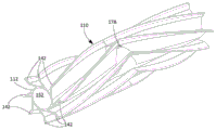
叶片114可以沿着壳体112形成人字形图案。例如,叶片114的区段174沿螺旋路径176沿着壳体112延伸,并且叶片114的区段174与区段168可以形成人字形图案。螺旋路径176因此沿着壳体112纵向和周向延伸。螺旋路径176在辊104的切线方向Z2(如图4C所示)上沿着壳体112从螺旋路径176的第一端176a延伸到螺旋路径176的第二端176b。螺旋路径176的第一端176a位于辊104的第二端部150附近,螺旋路径176的第二端176b位于中心横截面172附近。区段174从辊104的第二端部150延伸到中心横截面172。叶片114的区段168在中心横截面172处连接到叶片114的区段174。在一些实施方式中,区段168和区段174关于中心横断面172彼此对称。螺旋路径170的螺距和螺旋路径176的螺距可为300毫米至900毫米,例如300至600毫米、400至700毫米、500至800毫米或600至900毫米。The
在一些实施方式中,辊104包括布置在辊104的中心113处或其附近的开口178。通过减小叶片114朝向辊104中心113附近的部分的刚度,开口178可以减弱辊104接触地板表面时由辊104产生的噪声。在一些实施方式中,开口178关于辊104的中心横截面172对称。In some embodiments, the
开口178(也在图4A中示出)沿着辊104的中心部分182的至少一部分延伸(例如辊104的关于中心横截面172对称的长度部分,该部分的长度为辊104的长度L1的25%至50%之间)。开口178可以自壳体112向外朝向辊104的外圆周延伸,并且可以延伸穿过叶片114。例如,开口178可以仅部分地穿过叶片114朝向叶片114的尖端部分154(在图4B中示出)延伸。在一些实施方式中,开口178从壳体112朝着叶片114的尖端部分154向外延伸。开口178朝着叶片114的尖端部分154逐渐变细。例如,从靠近壳体112的地方至靠近叶片114的尖端部分154的地方,开口178沿着纵向轴线X1的长度会减小。开口178沿着纵向轴线X1的最大长度L4可以为15到45毫米,例如15到30毫米、20到35毫米、25到40毫米或30到45毫米。The opening 178 (also shown in FIG. 4A ) extends along at least a portion of the
如图4F所示,在一些实施方式中,开口178延伸穿过叶片114的第一部分116的全部(例如穿过叶片114的第一部分116的整个长度),并且不穿过叶片114的第二部分118或仅穿过第二部分118的一部分。例如,开口178在远端终止点179处终止,该远端终止点179与叶片114的第二部分118的第一端118a(如图4B所示)重合。该远端终止点179与一个位置重合,在该位置处叶片114的第一部分116附接到叶片114的第二部分118。(沿着叶片114的区段168的)叶片114的第一部分116与(沿着叶片114的区段174的)叶片114的第一部分116相分离。特别地,(沿着叶片114的区段168的)叶片114的第一部分116的区段通过开口178与(沿着叶片114的区段174的)叶片114的第一部分116的区段分离。叶片114的第二部分118可以沿着叶片114从辊104的第一端部149连续地延伸到辊104的第二端部150,例如沿着辊104的长度L1(如图1B所示)的至少90%至95%。尽管描述为延伸穿过叶片114的第一部分116的全部,但是在一些实施方式中,开口178可以仅部分地延伸穿过叶片114的第一部分116,并且不延伸穿过叶片114的第二部分118。As shown in FIG. 4F , in some embodiments, the
开口178可以是多个开口180中的一个开口,开口180中的每一个开口都延伸穿过叶片142中的一个相应的叶片。开口180中的每一个开口可具有类似于关于开口178所描述的特征。在一些实施方式中,开口180中的每一个开口可以仅延伸穿过叶片114的第一部分116的一部分,例如仅沿着第一部分116的底部,其中在第一部分116的底部,第一部分116附接至伸长部件107。开口180可以通过减少辊104的整体刚度来减少驱动辊104的整体能耗。The
替代实施方式Alternative implementation
已经描述了多个实施方式,然而,应当理解,可以进行各种修改。本申请结合辊104或其他本申请描述的辊描述了某些实施方式。结合这些实施方式描述的特征不限于这些实施方式,并且可应用于其他实施方式。A number of embodiments have been described, however, it should be understood that various modifications may be made. Certain embodiments are described herein in conjunction with
尽管将机器人102被描述为具有矩形的前部202a和半圆形的后部202b,但是在一些实施方式中,机器人102的外周限定另一种合适的形状。例如,在某些情况下,机器人102的主体200具有近似圆形的形状。可替代地,机器人102的主体200具有近似矩形的形状、近似方形的形状、近似椭圆形的形状或近似勒洛多边形(Reuleaux polygonal)的形状。Although the
尽管本申请描述的某些辊被描述为具有支撑结构,其中支撑结构具有芯,芯包括支撑部件和轴部,但在其他实施方式中该支撑结构可以不同。例如,辊104被描述为包括支撑结构109,支撑结构109又包括芯140和端盖141。芯140被描述为包括套筒144,支撑构件146a、146b、146c和轴部148。在某些实施方式中,支撑结构109可以是支撑护套110的整体式部件。在某些实施方式中,支撑结构109包括伸长部件107的一部分或对应于伸长部件107。例如,在一些实施方式中,叶片114可以直接附接到支撑结构109。在一些实施方式中,叶片114与支撑结构109是一体的。Although some of the rollers described herein are described as having a support structure with a core including a support member and a shaft portion, in other embodiments the support structure may be different. For example, roll 104 is depicted as including
尽管护套110被描述为具有圆柱形壳体112,但是在一些实施方式中,壳体112包括截头圆锥形部分。例如,壳体112可包括由辊104的中心横截面172划分的两个半部。两个半部可各自为截头圆锥形。辊104的叶片142可从壳体112向外延伸,使得护套110的外径沿着护套110的长度是均匀的。Although the
支撑结构109被描述为位于护套110内。在一些实施方式中,支撑结构109包括与护套110的部件分离的部件。在一些实施方式中,支撑结构109和护套110彼此互成一体。例如,辊104可以是整体结构。辊104可以是包括叶片142的实心结构。在一些示例中,辊104是实心结构而不包括壳体112和支撑结构109,辊104可以包括沿着辊104的纵向轴线X1延伸的杆构件。叶片114可沿杆构件延伸。杆构件可以是实心的。
尽管本申请将某些辊描述为具有多个叶片,但是在一些实施方式中,辊可以包括单个叶片。例如,尽管辊104被描述为具有多个叶片142,但是在一些实施方式中,辊104包括单个叶片,例如叶片114。Although this application describes certain rollers as having multiple vanes, in some embodiments the rollers may include a single vane. For example, although the
本申请中将某些辊描述为具有叶片,其中叶片具有沿着螺旋路径延伸的部分,螺旋路径沿着伸长部件延伸。在某些实施方式中,叶片的沿着这些螺旋路径延伸的这些部分和这些螺旋路径的轨迹可以变化。例如,虽然区段168和区段174被描述为是叶片114的在护套110的整个长度上延伸的一部分,但是在一些实施方式中,护套110包括沿着护套110的第一半部的整个长度延伸的第一叶片和沿着叶片110的第二半部的整个长度延伸的第二叶片。第一叶片和第二叶片的几何特征分别类似于本申请描述的叶片114的区段168、174的几何特征,但是不同点在于第一叶片和第二叶片彼此分开并且在圆周上彼此偏移,例如,沿切线方向彼此偏移。例如,第一叶片可以沿着第一螺旋路径延伸,该第一螺旋路径的螺距与本申请结合螺旋路径170所描述的螺距相似,并且第二叶片可以沿着第二螺旋路径延伸,该第二螺旋路径的螺距与本申请结合螺旋路径176所描述的螺距相似。用于第一叶片的第一螺旋路径的第一纵向端可以相对于用于第二叶片的第二螺旋路径的第一纵向端在圆周上偏移,例如,沿切线方向偏移。用于第一叶片的第一螺旋路径的第二纵向端可相对于用于第二叶片的第二螺旋路径的第二纵向端在周向上偏移,例如,沿切线方向偏移。Certain rollers are described in this application as having vanes, wherein the vanes have portions extending along a helical path extending along an elongated member. In certain embodiments, the portions of the blade extending along the helical paths and the trajectories of the helical paths may vary. For example, while
第一叶片可以从辊104的第一端部149至少延伸到辊104的中心横截面172,并且在一些实施方式中,可以延伸超过中心横截面172到护套110的第二半部。类似地,第二叶片可以从辊104的第二端部150至少延伸到辊104的中心横截面172,并且在一些实施方式中,可以延伸超过中心横截面172到护套110的第一半部。因此,第一叶片和第二叶片可沿辊104的中心部分182的至少一部分在周向上彼此重叠。The first vane may extend from the
第一叶片可以是沿着辊104的第一半部的第一组叶片的一部分,第二叶片可以是沿着辊104的第二半部的第二组叶片的一部分,其中第一组叶片自沿着辊104的第二半部的第二组叶片沿周向偏移,使得第一组叶片与第二组叶片相分离。第一组叶片中的每个叶片位于第二组叶片中的对应叶片对之间,第二组叶片中的每个叶片位于第一组叶片中的对应叶片对之间。The first vane may be part of a first set of vanes along the first half of the
尽管叶片114被描述为具有沿着反向螺旋路径延伸的区段168、174,但是在一些实施方式中,参考图7,护套702的叶片704沿着螺旋路径706延伸,其中螺旋路径706沿着护套702的整个长度延伸。螺旋路径706的螺距可以为300至900毫米,例如300至600毫米、400至700毫米、500至800毫米或600至900毫米。Although the
尽管叶片114的部分沿其延伸的螺旋路径被描述为具有螺距,但是在一些实施方式中,螺旋路径的螺距在辊104的整个长度上可能是不均匀的。在一些实施方式中,螺旋路径170或螺旋路径176的螺距可以变化,例如,从辊104的外端部朝向辊104的中心113增加或减少。Although the helical path along which portions of the
本申请所述的某些辊包括沿辊的叶片的开口。例如,在一些实施方式中,辊104被描述为具有靠近辊104的中心113的单个开口178。在一些实施方式中,辊104包括沿着叶片114的长度布置的多个开口。多个开口彼此分开并且可以在叶片114的整个长度上对称分布。例如,多个开口关于中心横截面172对称。Certain rolls described herein include openings along the blades of the roll. For example, in some embodiments, the
除了从辊的伸长部件向外延伸的叶片之外,本申请描述的某些辊可以包括其他特征。在一些实施方式中,辊包括凸块(nub),其用于将辊支撑在机器人下方的地板表面上的障碍物上。例如,参考图5A,护套502可类似于护套110(图4A所示),唯一不同点在于护套502包括从伸长部件(例如,护套502的壳体506,其类似于壳体112))向外延伸而远离辊的纵向轴线X2(未示出)的凸块504。凸块504可以是从壳体506伸出的刚性突起。特别地,叶片503(类似于本申请所述的叶片114)可以比凸块504相对地更易弯曲。当辊移动经过地板平面上的障碍物时,叶片503可响应于与障碍物的接触而弯曲。响应于与障碍物的接触,凸块504可相对于叶片503而较小地弯曲。叶片503可以弯曲一定的量,使得在叶片503弯曲时叶片503相对于壳体506的高度小于在凸块504弯曲时凸块504相对于壳体506的高度。凸块504可以相应地将辊支撑在障碍物上,从而允许辊移动通过障碍物。在一些实施方式中,除了凸块504延伸所沿的螺旋路径周向偏离叶片503延伸所沿的螺旋路径之外,凸块504延伸所沿的螺旋路径类似于叶片503延伸所沿的螺旋路径(例如,螺旋路径170)。Certain rollers described herein may include other features in addition to vanes extending outwardly from the elongated members of the rollers. In some embodiments, the rollers include nubs for supporting the rollers on obstacles on the floor surface below the robot. For example, referring to FIG. 5A, the
参考图5B,叶片503的外尖端部分510相对壳体506或在壳体506之上的高度H2大于凸块504的外尖端部分512相对于壳体506或在壳体506之上的高度H3。可以选择相对于高度H2的高度H3,使得叶片503在凸块504与机器人下方的障碍物相互作用之前接触凸块504。例如,如果辊接触地板表面上的障碍物,叶片503可响应于该接触而弯曲。当叶片503弯曲时,叶片503朝向凸块504移动,直到叶片503接触凸块504为止。支撑在凸块504上的叶片503可以接触障碍物。叶片503和凸块504因此可以一起将辊支撑在障碍物上,从而允许辊移动通过障碍物。高度H2可以比高度H3大25%到150%,例如比高度H3大25%到50%、50%到75%、75%到100%。凸块504的高度H3可以为0.25至2.0厘米,例如0.25至1.5厘米、0.5至2厘米、0.5至1.5厘米或0.6至1.2厘米。5B, the height H2 of the
凸块504可以从壳体506到凸块504的尖端部分512逐渐变细。凸块504的最大厚度可以为8至18毫米,例如8至14毫米、10至16毫米或12至18毫米。凸块504的最大厚度可以位于凸块504的底部,在此处凸块504附接至壳体506。凸块504可以是基本上三角形的或具有三角形的部分。例如,凸块504可以包括面对切线方向Z3的表面514和面对切线方向Z4的表面516,表面514和表面516形成了自壳体506的大致三角形凸起的两边。The
参考图5C,表面514的长度L5大于表面516的长度L6,其中L5就是凸块504的尖端部分512和表面514的沿着壳体506的位置之间的距离,L6就是凸块504的尖端部分512和表面516的沿着壳体506的位置之间的距离。例如,长度L5可以是长度L6的1.5至2.5倍。回到图5B,表面514和延伸穿过凸块504的尖端部分512的径向轴线Y4之间的角度可以为30度到60度,表面514和径向轴线Y4之间的角度可以为不大于15度。5C, the length L5 of the
凸块504可以是护套502的多个凸块518中的一个凸块。例如,如图5B所示,护套502可包括两个凸块518。在其他实施方式中,护套502可包括更少或更多的凸块,例如1个凸块、3个凸块、4个凸块、5个凸块、6个凸块、7个凸块、8个凸块或更多。叶片503可周向地布置在两个凸块518之间。在护套502包括多个叶片520(类似于叶片142)的实施方式中,每个凸块518周向地布置在彼此相邻的两个对应的叶片520之间。类似于叶片142,凸块518可沿沿着壳体506的外表面的螺旋路径延伸,这些螺旋路径的螺距类似于叶片520的螺旋路径的螺距。The
辊的凸块的构造在某些实施方式中可以变化。在一些实施方式中,参考图6A,护套602可以类似于护套502,唯一不同点在于护套602的凸块604包括开口606。开口606可以用于容纳柔韧的毛刷。柔韧的毛刷可以是包含柔软硬毛的伸长部件。该伸长部件可穿过开口606从凸块604的第一纵向端延伸到凸块的第二纵向端。伸长部件的刷毛可用于清除和搅动地板表面上的碎屑。The configuration of the bumps of the rollers may vary in certain embodiments. In some embodiments, referring to FIG. 6A , the
凸块604位于两个叶片之间,包括叶片610和叶片611。开口606位于伸长部件(例如护套602的壳体608,其类似于壳体112)附近。类似于凸块504,凸块604可以比护套602的叶片610(类似于叶片114)更硬,并且可以具有与凸块504的几何特征相似的、为凸块604提供刚性的几何特征,例如凸块604的最大厚度可以类似于凸块504的最大厚度,并且凸块604的高度可以类似于凸块504的高度H3。在一些实施方式中,可以选择凸块604的高度,使得凸块604可以直接接触机器人下方的障碍物并允许辊移动通过障碍物。与一些实施方式中叶片接触凸块并且叶片和凸块一起将辊支撑在障碍物上有所不同,在一些实施方式中,凸块直接接触障碍物并将辊支撑在障碍物上。与叶片和凸块共同将辊支撑在障碍物上的实施方式相比,在这样的实施方式中,凸块和叶片的相对高度差异更大。例如,在凸块直接将辊支撑在障碍物上的实施方式中,凸块的高度可以是叶片高度的至少35%,例如是叶片高度的至少40%、至少45%或至少50%。在叶片弯曲后凸块通过叶片将辊支撑在障碍物上的实施方式中,凸块的高度最大为叶片高度的70%,例如最大为叶片高度的65%、60%、55%或50%。在这样的实施方式中,凸块还防止叶片在接触凸块之后进一步弯曲。凸块是通过叶片将辊支撑在障碍物上还是直接将辊支撑在障碍物上还取决于辊与凸块之间的切向距离以及叶片的可弯曲性。
参考图6B,开口606可包括矩形或正方形的横截面部分。开口606可具有2毫米到8毫米的最大宽度。Referring to Figure 6B, the
参考图6C,凸块604包括面对第一切线方向的表面654以及另外一组表面,该一组表面包括面对第二切线方向的表面656、658、660和662。表面654、656、658、660、662都是直的。表面662从壳体608向外延伸,表面660从表面662向外延伸,开口606在表面662和表面658之间延伸,表面658从开口606向外延伸,并且表面656从表面658向外延伸。表面658和表面654在凸块604的尖端部分664处相遇。Referring to Figure 6C,
开口606自表面658、660径向向内延伸。开口606面向第二切线方向。开口606包括与第二部分652相邻的第一部分650。第一部分650从表面658、660延伸到开口606的第二部分652。第一部分650可以是矩形的。第二部分652自第一部分650朝向壳体608延伸。第二部分652是矩形的。第二部分652相对于第一部分650径向向内,因此相对于开口606的第一部分650,第二部分652距离辊的纵轴更近。第一部分650具有宽度W2,第二部分652具有宽度W3。宽度W2小于宽度W3。宽度W2为1至4毫米,例如1至3毫米、1.5至3.5毫米或2至4毫米。宽度W3是宽度W2的1.5至2.5倍。
在一些实施方式中,如图6B所示,除了叶片610可包括第一部分612、第二部分614和第三部分616之外,护套602可以与护套502相类似。叶片610可包括第一弯折618和第二弯折620,其中第一部分612在第一弯折618处附接到第二部分614,第二部分614在第二弯折620处附接到第三部分616。第一弯折618位于壳体608和第二弯折620之间,第二弯折620位于第一弯折618和叶片610的尖端部分622之间。第一部分612的第一端612a在与辊的径向轴线Y5(未示出)相交的位置处附接到壳体608,第二部分612的第二端612b在第一弯折618处附接到第二部分614的第一端614a。第二部分614的第二端614b在第二弯折620处附接到第三部分616的第一端616a。第三部分616终止于尖端部分622.In some embodiments,
第一部分612、第二部分614和第三部分616分别沿着轴线y4、y5、y6延伸。轴线y4和径向轴线Y5之间的角度类似于本申请所述的轴线y1和径向轴线Y1之间的角度。轴线y4和径向轴线Y5之间的角度大于轴线y5和径向轴线Y5之间的角度。轴线y6与径向轴线Y5之间的角度可以基本上类似于轴线y4与径向轴线Y5之间的角度,例如,在轴线y4与径向轴线Y5之间的角度的5%至15%之内。例如,轴线y6和轴线y4之间的角度不大于5至15度。轴线y5和径向轴线Y5之间的角度小于轴线y6和径向轴线Y6之间的角度。在一些实施方式中,轴线y6平行于轴线y4。在一些实施方式中,轴线y6和径向轴线Y5之间的角度可以小于轴线y4和径向轴线Y5之间的角度。The
轴线y4和轴线y5之间的角度可以为90度至170度,例如90度至150度、90度至130度或90度至110度,或大约为95度、105度或115度。轴线y5和轴线y6之间的角度可以为90度至170度,例如90度至150度、90度至130度或90度至110度,或大约为95度、105度或115度。轴线y4和轴线y6之间的角度可以小于20度,例如小于15度、小于10度或小于5度。The angle between axis y4 and axis y5 may be 90 to 170 degrees, such as 90 to 150 degrees, 90 to 130 degrees or 90 to 110 degrees, or approximately 95, 105 or 115 degrees. The angle between axis y5 and axis y6 may be 90 to 170 degrees, such as 90 to 150 degrees, 90 to 130 degrees or 90 to 110 degrees, or approximately 95, 105 or 115 degrees. The angle between axis y4 and axis y6 may be less than 20 degrees, eg, less than 15 degrees, less than 10 degrees, or less than 5 degrees.
叶片610的第一部分612和第二部分614的厚度类似于关于本申请叶片114的第一部分116和第二部分118描述的厚度。在一些实施方式中,第三部分616的厚度可以朝向尖端部分622逐渐变细。The thicknesses of the
叶片610的第一部分612的长度L7为0.5至3厘米,例如0.5至2.5厘米、0.5至2厘米或1至2厘米。叶片610的第二部分614的长度L8为0.2至1厘米,例如0.2至0.8厘米或0.4至1.0厘米。叶片610的第三部分616的长度L9为0.2至0.8厘米,例如0.2至0.6厘米或0.4至0.8厘米。长度L9是长度L7的10%到30%,例如是长度L7的10%到20%、15%到25%或者20%到30%。长度L9是长度L8的60%至90%,例如是长度L8的60%至80%、65%至85%或70%至90%。长度L8是长度L7的15%至35%,例如是长度L7的15%至25%、20%至30%或25%至35%。The length L7 of the
尽管开口178被描述为朝着叶片114的外部尖端逐渐变细,但是在一些实施方式中,开口178、开口180或其组合可以是延伸穿过叶片114的厚度的狭缝。狭缝具有均匀的宽度,并且可以延伸穿过叶片114的第一部分116的整个长度,或者仅延伸穿过叶片114的第一部分116的一部分。Although opening 178 is depicted as tapering toward the outer tip of
图4B中示出的叶片114的第一部分116和图6B中示出的第一部分612、第二部分614都被描述为具有均匀厚度的笔直部分,其中面对第一切线方向的表面基本上平行于面对第二切线方向的表面。在一些实施方式中,这些部分可以包括弯曲、突起、不均匀的厚度或其他几何特征。The
相较于针对单个辊104描述的一些前述示例,在一些实施方式中,机器人102可以包括多个辊。例如,机器人102可以包括两个辊。在一些实施方式中,第一辊与第二辊不同,例如,第一辊可包括与第二辊的特征不相同的某些特征。In contrast to some of the preceding examples described for a
尽管辊104被描述为具有护套110,并且伸长部件107被描述为对应于护套110的壳体112,但是在其他实施方式中伸长部件107可以变化。在一些实施方式中,伸长部件107是圆柱形杆、方杆或其他棱柱杆。在一些实施方式中,伸长部件107是中空的,并且在一些实施方式中,伸长部件107是实心的。参考图8,辊800包括叶片802和伸长部件804。叶片802可在几何上类似于本文所述的任何叶片,例如叶片114。与叶片114相比,叶片802的不同之处在于伸长部件804,并且相对于伸长部件804可纵向滑动。具体地,为了组装辊800,叶片802安装在沿伸长部件804纵向延伸的狭槽806上。叶片802包括装配在狭槽806内的近端部分808。近端部分808被配置为阻止叶片802相对于伸长部件804径向向外移动。例如,近端部分808包括在径向向外的方向上的锥度,并且狭槽806也在径向向外的方向上逐渐变细。在一些实施方式中,伸长部件804是辊800的护套的一部分。在进一步的实施方式中,伸长部件804是辊800的芯的一部分。Although the
尽管以辊800为例进行了描述,但是叶片802的特征可适用于其他实施方式。例如,在一些实施方式中,辊104的叶片114可以包括与叶片802的特征相似的特征。在一些实施方式中,如果辊包括凸块,则这些凸块可以沿着伸长部件滑动到狭槽中。Although described using the example of
如本申请所述,在清洁辊包括凸块的实施方式中,凸块的数量和构造可以变化。在图5A所示的例子中,辊包括两个凸块518。参考图9,用于清洁辊的护套900可包括凸块902和叶片904。凸块902可具有与凸块518的几何构造相似的几何构造。As described herein, in embodiments where the cleaning roll includes bumps, the number and configuration of the bumps may vary. In the example shown in FIG. 5A , the roller includes two
如本申请所述,凸块902和叶片904被构造成:当辊接触机器人下方的地板表面上的障碍物时,使得凸块902接触叶片904。就这一点而言,当辊移动通过障碍物时,叶片904弯曲与凸块902接触,并且叶片904和凸块902将辊支撑在障碍物上,以允许辊清除障碍物。与护套502不同,护套900包括与每个叶片904相对应的凸块902。具体地,如图9所示,每个凸块902在逆时针方向上与对应的叶片904相邻,防止相应的叶片904在叶片904接触凸块902之后进一步弯曲。在一些实施方式中,凸块902防止叶片904的第一部分(类似于本申请中描述的第一部分116)在叶片904接触凸块902之后进一步弯曲。例如,凸块902的高度最大为叶片904的高度的50%,例如最大为叶片904的高度的40%、35%或30%。As described herein, the
如本申请所述,在一些实施方式中,可将凸块配置成:当叶片接触地板表面上的障碍物时,使得叶片不接触凸块。在图10所示的例子中,护套1000包括叶片1002a、1002b和凸块1004a、1004b。与凸块518不同,凸块1004a、1004b不是三角形的,而是沿着一个轨迹径向向外延伸,该轨迹类似于叶片1002a、1002b的轨迹。特别地,凸块1004a、1004b可包括多个互连部分,该多个互连部分位于沿着凸块1004a、1004b的弯折处。As described herein, in some embodiments, the bumps may be configured such that the blades do not contact the bumps when the blades contact obstacles on the floor surface. In the example shown in Figure 10, the
凸块1004a、1004b被配置为在叶片1002a、1002b弯曲而与凸块1004a、1004b接触之前在机器人下方的地板表面上接触障碍物。特别地,如图10所示,在顺时针方向上与凸块1004a、1004b相邻的叶片1002a、1002b沿逆时针方向弯曲。当叶片1002a、1002b弯曲时,叶片1002a、1002b相对于护套1000的壳体1006的高度减小到低于凸块1004a、1004b的高度的位置,并且在接触凸块1004a、1004b之前减小到该位置。凸块1004a、1004b可包括弯折1008a、1008b,弯折1008a、1008b允许凸块1004a、1004b沿切线方向远离叶片1002a、1002b延伸。与厚度从壳体1006向外逐渐变小的凸块518不同,凸块1004a、1004b的厚度可以从靠近壳体1006处到靠近凸块1004a、1004b的远侧末端处保持均匀。均匀的厚度可以比叶片1002a、1002b的厚度更厚,使得凸块1004a、1004b可以更容易地将辊支撑在地板表面上的障碍物上。例如,凸块1004a、1004b可以比叶片1002a、1002b厚50%至200%,例如,比叶片1002a、1002b厚50%至150%、75%至175%或100%至200%。The
在图11所示的例子中,护套1100包括叶片1102a、1102b、1102c、1102d和凸块1104a、1104b、1104c、1104d。图11展示的示例与图10展示的示例相似的地方在于,凸块1104a、1104b、1104c和1104d被配置为在叶片1102a、1102b、1102c和1102d分别弯曲到与凸块1104a、1104b、1104c、1104d接触之前就接触地板表面上的机器人下的障碍物。凸块1104a、1104b、1104c、1104d具有的最大厚度大于图10所描述的凸块1004a、1004b的厚度。在一些实施方式中,凸块1104a、1104b、1104c、1104d的最大厚度类似于本申请其他地方所述的凸块518或凸块604的最大厚度。如图11所示,凸块1104a、1104b、1104c、1104d具有相对于与凸块1104a、1104b、1104c、1104d相邻的叶片1102a、1102b、1102c、1102d沿顺时针方向足够的高度和距离,以便当叶片1102a、1102b、1102c、1102d响应于与地板表面上的障碍物的接触而弯曲时,在凸块1104a、1104b、1104c、1104d接触障碍物之前,叶片1102a、1102b、1102c、1102d不接触凸块1104a、1104b、1104c、1104d。在与障碍物接触时,凸块1104a、1104b、1104c、1104d可以帮助辊在障碍物上移动。In the example shown in Figure 11, the
关于一些实施方式描述的特征可以参考其他实施方式中的特征以进行组合或修改。相应的,其他实施方式也在本申请权利要求的范围之内。Features described in relation to some embodiments may be combined or modified with reference to features in other embodiments. Accordingly, other implementations are also within the scope of the claims of the present application.
Claims (10)
Applications Claiming Priority (2)
| Application Number | Priority Date | Filing Date | Title |
|---|---|---|---|
| US16/288,699 US11109727B2 (en) | 2019-02-28 | 2019-02-28 | Cleaning rollers for cleaning robots |
| US16/288,699 | 2019-02-28 |
Publications (1)
| Publication Number | Publication Date |
|---|---|
| CN211674046U true CN211674046U (en) | 2020-10-16 |
Family
ID=72237067
Family Applications (9)
| Application Number | Title | Priority Date | Filing Date |
|---|---|---|---|
| CN202510219272.9A Pending CN119924735A (en) | 2019-02-28 | 2020-02-26 | Cleaning rollers for cleaning robots |
| CN202020214909.8U Active CN212037385U (en) | 2019-02-28 | 2020-02-26 | Cleaning roller capable of being mounted on cleaning robot and cleaning robot |
| CN202020214895.XU Active CN211674045U (en) | 2019-02-28 | 2020-02-26 | Cleaning rollers that can be attached to cleaning robots and cleaning robots |
| CN202211040672.6A Active CN115281560B (en) | 2019-02-28 | 2020-02-26 | Cleaning rollers for cleaning robots |
| CN202020214922.3U Active CN211674046U (en) | 2019-02-28 | 2020-02-26 | Cleaning rollers that can be attached to cleaning robots and cleaning robots |
| CN202510219218.4A Pending CN119924734A (en) | 2019-02-28 | 2020-02-26 | Cleaning rollers for cleaning robots |
| CN202020214841.3U Active CN211674044U (en) | 2019-02-28 | 2020-02-26 | Cleaning rollers that can be attached to cleaning robots and cleaning robots |
| CN202020214891.1U Active CN212394807U (en) | 2019-02-28 | 2020-02-26 | Cleaning roller capable of being mounted on cleaning robot and cleaning robot |
| CN202010119907.5A Active CN111616646B (en) | 2019-02-28 | 2020-02-26 | Cleaning roller for cleaning robot |
Family Applications Before (4)
| Application Number | Title | Priority Date | Filing Date |
|---|---|---|---|
| CN202510219272.9A Pending CN119924735A (en) | 2019-02-28 | 2020-02-26 | Cleaning rollers for cleaning robots |
| CN202020214909.8U Active CN212037385U (en) | 2019-02-28 | 2020-02-26 | Cleaning roller capable of being mounted on cleaning robot and cleaning robot |
| CN202020214895.XU Active CN211674045U (en) | 2019-02-28 | 2020-02-26 | Cleaning rollers that can be attached to cleaning robots and cleaning robots |
| CN202211040672.6A Active CN115281560B (en) | 2019-02-28 | 2020-02-26 | Cleaning rollers for cleaning robots |
Family Applications After (4)
| Application Number | Title | Priority Date | Filing Date |
|---|---|---|---|
| CN202510219218.4A Pending CN119924734A (en) | 2019-02-28 | 2020-02-26 | Cleaning rollers for cleaning robots |
| CN202020214841.3U Active CN211674044U (en) | 2019-02-28 | 2020-02-26 | Cleaning rollers that can be attached to cleaning robots and cleaning robots |
| CN202020214891.1U Active CN212394807U (en) | 2019-02-28 | 2020-02-26 | Cleaning roller capable of being mounted on cleaning robot and cleaning robot |
| CN202010119907.5A Active CN111616646B (en) | 2019-02-28 | 2020-02-26 | Cleaning roller for cleaning robot |
Country Status (6)
| Country | Link |
|---|---|
| US (4) | US11109727B2 (en) |
| EP (2) | EP3962321B1 (en) |
| JP (4) | JP7055936B2 (en) |
| CN (9) | CN119924735A (en) |
| MY (1) | MY209724A (en) |
| WO (1) | WO2020176160A1 (en) |
Cited By (2)
| Publication number | Priority date | Publication date | Assignee | Title |
|---|---|---|---|---|
| CN114947639A (en) * | 2022-05-13 | 2022-08-30 | 小窝智能(北京)科技有限公司 | Cleaning equipment |
| CN115625840A (en) * | 2020-12-31 | 2023-01-20 | 帝舍智能科技(武汉)有限公司 | Sponge roller, forming die and forming method |
Families Citing this family (20)
| Publication number | Priority date | Publication date | Assignee | Title |
|---|---|---|---|---|
| CN208693165U (en) | 2015-10-21 | 2019-04-05 | 尚科宁家运营有限公司 | Surface cleaning head with dual rotary agitators |
| US11647881B2 (en) | 2015-10-21 | 2023-05-16 | Sharkninja Operating Llc | Cleaning apparatus with combing unit for removing debris from cleaning roller |
| US11202542B2 (en) | 2017-05-25 | 2021-12-21 | Sharkninja Operating Llc | Robotic cleaner with dual cleaning rollers |
| US10638907B2 (en) | 2017-09-15 | 2020-05-05 | Omachrom Intellectual Property Inc. | Surface cleaning apparatus |
| US11109727B2 (en) * | 2019-02-28 | 2021-09-07 | Irobot Corporation | Cleaning rollers for cleaning robots |
| USD938114S1 (en) * | 2019-03-22 | 2021-12-07 | Sungrow Power Supply Co., Ltd. | Intelligent cleaning robot |
| USD979865S1 (en) * | 2019-06-14 | 2023-02-28 | Sharkninja Operating Llc | Brush roll |
| USD979866S1 (en) * | 2019-06-14 | 2023-02-28 | Sharkninja Operating Llc | Brush roll |
| GB2588158B (en) * | 2019-10-10 | 2022-02-23 | Dyson Technology Ltd | Cleaner head for a vacuum cleaning appliance |
| WO2022051635A1 (en) * | 2020-09-04 | 2022-03-10 | Sharkninja Operating Llc | Agitator for a surface treatment apparatus and a surface treatment apparatus having the same |
| US11684227B2 (en) * | 2021-06-02 | 2023-06-27 | Bissell Inc. | Surface cleaning apparatus having a brushroll |
| US11832780B2 (en) | 2021-07-29 | 2023-12-05 | Irobot Corporation | Mobile cleaning robot dustpan |
| KR20230107038A (en) * | 2022-01-07 | 2023-07-14 | 삼성전자주식회사 | Vacuum cleaner |
| JP1797122S (en) * | 2022-12-30 | 2025-04-24 | Rotating brush for cleaning robot | |
| EP4716491A1 (en) | 2023-05-23 | 2026-04-01 | SharkNinja Operating LLC | Cleaning apparatus |
| USD1105672S1 (en) | 2023-08-30 | 2025-12-09 | Sharkninja Operating Llc | Vacuum cleaner and vacuum nozzle |
| GB2640139A (en) * | 2024-04-03 | 2025-10-15 | Dyson Technology Ltd | Floor cleaning roller |
| GB2640141A (en) * | 2024-04-03 | 2025-10-15 | Dyson Technology Ltd | Floor cleaning roller |
| GB2640137A (en) * | 2024-04-03 | 2025-10-15 | Dyson Technology Ltd | Floor cleaning roller |
| USD1113019S1 (en) | 2024-05-31 | 2026-02-10 | Sharkninja Operating Llc | Steam cleaner |
Family Cites Families (281)
| Publication number | Priority date | Publication date | Assignee | Title |
|---|---|---|---|---|
| GB157616A (en) | 1919-11-24 | 1921-01-27 | Wilmort Mfg Company | Improvements in crumb sweepers |
| BE333794A (en) | 1926-01-12 | |||
| US1907642A (en) * | 1930-02-03 | 1933-05-09 | Hoover Co | Suction cleaner |
| US1919067A (en) | 1932-10-07 | 1933-07-18 | Electric Vacuum Cleaner Co | Beater for vacuum cleaners |
| US2064856A (en) | 1935-05-25 | 1936-12-22 | Air Way Electric Appl Corp | Vacuum cleaner |
| US2298682A (en) | 1940-11-08 | 1942-10-13 | Lennart Wilklund | Arrangement for painting |
| US2578549A (en) | 1948-07-26 | 1951-12-11 | Robert O Hooban | Power-driven clothes-cleaning brush |
| US2770825A (en) | 1951-09-10 | 1956-11-20 | Bissell Carpet Sweeper Co | Carpet sweeper and brush cleaning combs therefor |
| US2881461A (en) | 1956-10-29 | 1959-04-14 | Wynton E Parker | Paint roller for curved surfaces |
| AT312860B (en) | 1970-07-28 | 1974-01-25 | Leifheit International | Roller-shaped brush for sweepers, in particular for carpet sweepers |
| DE2243267A1 (en) | 1971-09-13 | 1973-03-22 | Geb Hoffmann Christa D Pankoke | MACHINE FOR THE PRODUCTION OF WOOD FIBER PANELS |
| US4042997A (en) | 1976-10-29 | 1977-08-23 | Bissell, Inc. | Vacuum cleaner with improved brush |
| JPS55104929A (en) | 1979-02-02 | 1980-08-11 | Owens Illinois Inc | Heated gob detector for glass product forming machine |
| JPS5644545A (en) | 1979-09-20 | 1981-04-23 | Matsushita Electric Ind Co Ltd | Controller of air conditioner |
| US4307479A (en) | 1979-10-19 | 1981-12-29 | Superior Brush Company | Angle tufted rotary brush assembly |
| EP0051996B1 (en) | 1980-11-10 | 1986-11-26 | Wheel Developments Limited | Wheel with resilient spokes |
| US4357727A (en) | 1980-12-04 | 1982-11-09 | Bissell, Inc. | Dual brush floor sweeper |
| US4401909A (en) | 1981-04-03 | 1983-08-30 | Dickey-John Corporation | Grain sensor using a piezoelectric element |
| US4552505A (en) | 1982-11-19 | 1985-11-12 | American Robot Corporation | Industrial robot having direct coaxial motor drive |
| US4832098A (en) | 1984-04-16 | 1989-05-23 | The Uniroyal Goodrich Tire Company | Non-pneumatic tire with supporting and cushioning members |
| JPS6133634A (en) * | 1984-07-25 | 1986-02-17 | 株式会社ホ−キイ | Rotary cleaning body in cleaner |
| US4679152A (en) | 1985-02-20 | 1987-07-07 | Heath Company | Navigation system and method for a mobile robot |
| JPS6261659A (en) | 1985-09-13 | 1987-03-18 | Hitachi Plant Eng & Constr Co Ltd | Seal air supply device for electrostatic precipitator |
| US4778113A (en) | 1986-04-29 | 1988-10-18 | The Babcock & Wilcox Company | Apparatus for monitoring low level combustibles |
| US4777691A (en) | 1986-10-20 | 1988-10-18 | National Union Electric Corporation | Motor driven brush assembly for vacuum cleaner |
| JPH0192960A (en) | 1987-10-02 | 1989-04-12 | Canon Inc | Information recording and reproducing device |
| US4912805A (en) | 1988-07-13 | 1990-04-03 | Black & Decker Inc. | Dual-purpose rotating brush for vacuum cleaner |
| JPH0223976A (en) | 1988-07-13 | 1990-01-26 | Eishin Giken:Kk | Cleaning roller in bowling lane maintenance device |
| US4962453A (en) | 1989-02-07 | 1990-10-09 | Transitions Research Corporation | Autonomous vehicle for working on a surface and method of controlling same |
| US4918441A (en) | 1988-12-22 | 1990-04-17 | Ford New Holland, Inc. | Non-contact sensing unit for row crop harvester guidance system |
| FR2648071B1 (en) | 1989-06-07 | 1995-05-19 | Onet | SELF-CONTAINED METHOD AND APPARATUS FOR AUTOMATIC FLOOR CLEANING BY EXECUTING PROGRAMMED MISSIONS |
| US5233682A (en) | 1990-04-10 | 1993-08-03 | Matsushita Electric Industrial Co., Ltd. | Vacuum cleaner with fuzzy control |
| JP2005053363A (en) | 2003-08-05 | 2005-03-03 | Shimano Inc | Hollow structural component part bicycle |
| US5109566A (en) | 1990-06-28 | 1992-05-05 | Matsushita Electric Industrial Co., Ltd. | Self-running cleaning apparatus |
| US5148569A (en) * | 1990-10-17 | 1992-09-22 | Bissell Inc. | Debris impeller |
| US5086535A (en) | 1990-10-22 | 1992-02-11 | Racine Industries, Inc. | Machine and method using graphic data for treating a surface |
| US5204814A (en) | 1990-11-13 | 1993-04-20 | Mobot, Inc. | Autonomous lawn mower |
| JPH0824655B2 (en) | 1990-11-26 | 1996-03-13 | 松下電器産業株式会社 | Electric vacuum cleaner |
| US5216777A (en) | 1990-11-26 | 1993-06-08 | Matsushita Electric Industrial Co., Ltd. | Fuzzy control apparatus generating a plurality of membership functions for determining a drive condition of an electric vacuum cleaner |
| DE4112382C2 (en) | 1991-04-16 | 2003-05-28 | Heinz Fritze | sweeper |
| US5321614A (en) | 1991-06-06 | 1994-06-14 | Ashworth Guy T D | Navigational control apparatus and method for autonomus vehicles |
| JP2761309B2 (en) | 1991-08-23 | 1998-06-04 | シャープ株式会社 | Vacuum cleaner floor suction |
| US5251355A (en) | 1991-10-17 | 1993-10-12 | Drumm Arthur E | Strip brush for mounting on a rotary drum |
| JP2761313B2 (en) | 1991-11-28 | 1998-06-04 | シャープ株式会社 | Vacuum cleaner floor suction |
| JPH05317226A (en) | 1991-12-02 | 1993-12-03 | Hookii:Kk | Rotary brush |
| DE4141802C2 (en) | 1991-12-18 | 1996-01-11 | Leifheit Ag | sweeper |
| DE4201596C2 (en) | 1992-01-22 | 2001-07-05 | Gerhard Kurz | Floor nozzle for vacuum cleaners |
| US5287591A (en) | 1992-03-30 | 1994-02-22 | Racine Industries, Inc. | Carpet cleaning machine with convertible-use feature |
| JP3177303B2 (en) | 1992-06-29 | 2001-06-18 | 三洋電機株式会社 | Vacuum cleaner floor suction |
| JPH0614853A (en) | 1992-06-30 | 1994-01-25 | Hitachi Ltd | Vacuum cleaner sucker |
| US5410479A (en) | 1992-08-17 | 1995-04-25 | Coker; William B. | Ultrasonic furrow or crop row following sensor |
| US5287589A (en) * | 1992-08-31 | 1994-02-22 | Container Products Corp. | Self-contained cleaning and retrieval apparatus |
| US5548511A (en) | 1992-10-29 | 1996-08-20 | White Consolidated Industries, Inc. | Method for controlling self-running cleaning apparatus |
| JPH0659578U (en) | 1993-01-29 | 1994-08-19 | コマニー株式会社 | Traveling device of moving wall and arrangement form of moving wall |
| JP3295744B2 (en) * | 1993-06-14 | 2002-06-24 | 株式会社コーワ | Suction nozzle for vacuum cleaner |
| US5452490A (en) | 1993-07-02 | 1995-09-26 | Royal Appliance Mfg. Co. | Brushroll with dual row of bristles |
| DE4325902C2 (en) | 1993-08-02 | 1999-12-02 | Bosch Gmbh Robert | Air charge calculation method for an internal combustion engine with variable gas exchange control |
| DE4400956C1 (en) | 1994-01-14 | 1994-10-20 | Vileda Gmbh | Sweeping roller |
| US5536953A (en) | 1994-03-08 | 1996-07-16 | Kobe Steel Usa | Wide bandgap semiconductor device including lightly doped active region |
| US5646494A (en) | 1994-03-29 | 1997-07-08 | Samsung Electronics Co., Ltd. | Charge induction apparatus of robot cleaner and method thereof |
| SE502834C2 (en) | 1994-03-29 | 1996-01-29 | Electrolux Ab | Method and apparatus for detecting obstacles in self-propelled apparatus |
| JP3293314B2 (en) | 1994-04-14 | 2002-06-17 | ミノルタ株式会社 | Cleaning robot |
| US5507067A (en) | 1994-05-12 | 1996-04-16 | Newtronics Pty Ltd. | Electronic vacuum cleaner control system |
| SE514791C2 (en) | 1994-06-06 | 2001-04-23 | Electrolux Ab | Improved method for locating lighthouses in self-propelled equipment |
| US5495634A (en) * | 1994-06-30 | 1996-03-05 | Bruns Brush Inc. (Ohio Corporation) | Vacuum sweeper roller brush |
| BE1008470A3 (en) | 1994-07-04 | 1996-05-07 | Colens Andre | Device and automatic system and equipment dedusting sol y adapted. |
| JP3183445B2 (en) | 1994-12-26 | 2001-07-09 | 東芝テック株式会社 | Suction port of vacuum cleaner and its rotary cleaning body |
| JPH08252199A (en) | 1995-01-18 | 1996-10-01 | Matsushita Electric Ind Co Ltd | Vacuum cleaner suction tool |
| US5710506A (en) | 1995-02-07 | 1998-01-20 | Benchmarq Microelectronics, Inc. | Lead acid charger |
| EP0815787B1 (en) | 1995-03-15 | 2002-12-11 | Hitachi, Ltd. | Suction piece for a vacuum cleaner |
| US5537711A (en) | 1995-05-05 | 1996-07-23 | Tseng; Yu-Che | Electric board cleaner |
| JPH08335112A (en) | 1995-06-08 | 1996-12-17 | Minolta Co Ltd | Mobile work robot system |
| JP3105778B2 (en) | 1995-10-23 | 2000-11-06 | 大淀小松株式会社 | Carpet cleaner and carpet cleaning method |
| JP3524662B2 (en) | 1995-12-06 | 2004-05-10 | 株式会社コーワ | Rotating rotor of floor nozzle for vacuum cleaner |
| US6220865B1 (en) | 1996-01-22 | 2001-04-24 | Vincent J. Macri | Instruction for groups of users interactively controlling groups of images to make idiosyncratic, simulated, physical movements |
| US6574536B1 (en) | 1996-01-29 | 2003-06-03 | Minolta Co., Ltd. | Moving apparatus for efficiently moving on floor with obstacle |
| JPH09263140A (en) | 1996-03-27 | 1997-10-07 | Minolta Co Ltd | Unmanned service car |
| US5935179A (en) | 1996-04-30 | 1999-08-10 | Aktiebolaget Electrolux | System and device for a self orienting device |
| JP3493539B2 (en) | 1996-06-03 | 2004-02-03 | ミノルタ株式会社 | Traveling work robot |
| US5815884A (en) | 1996-11-27 | 1998-10-06 | Yashima Electric Co., Ltd. | Dust indication system for vacuum cleaner |
| JP3375843B2 (en) | 1997-01-29 | 2003-02-10 | 本田技研工業株式会社 | Robot autonomous traveling method and autonomous traveling robot control device |
| US5942869A (en) | 1997-02-13 | 1999-08-24 | Honda Giken Kogyo Kabushiki Kaisha | Mobile robot control device |
| WO1998041822A1 (en) | 1997-03-20 | 1998-09-24 | Crotzer David R | Dust sensor apparatus |
| JPH1126084A (en) | 1997-06-30 | 1999-01-29 | Amp Japan Ltd | Card connector |
| KR100516315B1 (en) | 1997-08-25 | 2005-09-23 | 코닌클리케 필립스 일렉트로닉스 엔.브이. | Electric surface treatment device with an acoustic surface type detector |
| IL126149A (en) | 1997-09-09 | 2003-07-31 | Sanctum Ltd | Method and system for protecting operations of trusted internal networks |
| JPH11175118A (en) | 1997-10-08 | 1999-07-02 | Denso Corp | Robot controller |
| US6532404B2 (en) | 1997-11-27 | 2003-03-11 | Colens Andre | Mobile robots and their control system |
| EP1049964B1 (en) | 1997-11-27 | 2002-03-13 | Solar & Robotics | Improvements to mobile robots and their control system |
| JP3765356B2 (en) | 1997-12-22 | 2006-04-12 | ソニー株式会社 | Robot equipment |
| JPH11187994A (en) | 1997-12-26 | 1999-07-13 | Matsushita Electric Ind Co Ltd | Vacuum cleaner suction tool and vacuum cleaner using the same |
| JP3542264B2 (en) | 1998-02-05 | 2004-07-14 | 東芝テック株式会社 | Suction port for vacuum cleaner and vacuum cleaner having the same |
| US6263989B1 (en) | 1998-03-27 | 2001-07-24 | Irobot Corporation | Robotic platform |
| KR100384980B1 (en) | 1998-04-03 | 2003-06-02 | 마츠시타 덴끼 산교 가부시키가이샤 | Rotational brush device and electric instrument using same |
| KR20000002306A (en) | 1998-06-18 | 2000-01-15 | 배길성 | Rear wheel installation structure of moving robot for using cleaner |
| TW578540U (en) | 1998-07-28 | 2004-03-01 | Sharp Kk | Electric vacuum cleaner and nozzle unit therefor |
| EP1098587A1 (en) | 1998-07-31 | 2001-05-16 | Volker Sommer | Household robot for the automatic suction of dust from the floor surfaces |
| US6463368B1 (en) | 1998-08-10 | 2002-10-08 | Siemens Aktiengesellschaft | Method and device for determining a path around a defined reference position |
| US6505341B1 (en) | 1998-11-10 | 2003-01-07 | Scientronix, Inc. | System and method for programming a logic control unit |
| GB2344745B (en) | 1998-12-18 | 2002-06-05 | Notetry Ltd | Vacuum cleaner |
| GB9827779D0 (en) | 1998-12-18 | 1999-02-10 | Notetry Ltd | Improvements in or relating to appliances |
| GB2344863A (en) | 1998-12-18 | 2000-06-21 | Notetry Ltd | Connector for conduits |
| US6108853A (en) | 1999-02-04 | 2000-08-29 | Dittus; James D. | Vacuum cleaner beater brush |
| USD431698S (en) | 1999-04-28 | 2000-10-03 | Matsushita Electric Industrial Co., Ltd. | Rotary brush for electric vacuum cleaner |
| JP3594175B2 (en) | 1999-06-15 | 2004-11-24 | 東芝テック株式会社 | Vacuum cleaner and its suction body |
| ES2222906T3 (en) | 1999-06-17 | 2005-02-16 | SOLAR & ROBOTICS S.A. | AUTOMATIC OBJECT COLLECTION DEVICE. |
| US6539575B1 (en) | 1999-07-02 | 2003-04-01 | Oreck Holdings, Llc | Agitator for a cleaning machine with material cutting channel |
| GB9917232D0 (en) | 1999-07-23 | 1999-09-22 | Notetry Ltd | Method of operating a floor cleaning device |
| ATE306096T1 (en) | 1999-08-31 | 2005-10-15 | Swisscom Ag | MOBILE ROBOT AND CONTROL METHOD FOR A MOBILE ROBOT |
| JP2003515210A (en) | 1999-11-18 | 2003-04-22 | ザ プロクター アンド ギャンブル カンパニー | Household cleaning robot |
| US7155308B2 (en) | 2000-01-24 | 2006-12-26 | Irobot Corporation | Robot obstacle detection system |
| US6594844B2 (en) | 2000-01-24 | 2003-07-22 | Irobot Corporation | Robot obstacle detection system |
| US6530106B1 (en) | 2000-02-24 | 2003-03-11 | Bruns Brush, Inc. (Ohio Corporation) | Vacuum sweeper roller brush |
| US6490539B1 (en) | 2000-02-28 | 2002-12-03 | Case Corporation | Region of interest selection for varying distances between crop rows for a vision guidance system |
| US6285930B1 (en) | 2000-02-28 | 2001-09-04 | Case Corporation | Tracking improvement for a vision guidance system |
| US6278918B1 (en) | 2000-02-28 | 2001-08-21 | Case Corporation | Region of interest selection for a vision guidance system |
| JP2001277163A (en) | 2000-04-03 | 2001-10-09 | Sony Corp | Robot control device and control method |
| US6845297B2 (en) | 2000-05-01 | 2005-01-18 | Irobot Corporation | Method and system for remote control of mobile robot |
| US6385515B1 (en) | 2000-06-15 | 2002-05-07 | Case Corporation | Trajectory path planner for a vision guidance system |
| KR100391179B1 (en) | 2000-08-02 | 2003-07-12 | 한국전력공사 | Teleoperated mobile cleanup device for highly radioactive fine waste |
| US6674259B1 (en) | 2000-10-06 | 2004-01-06 | Innovation First, Inc. | System and method for managing and controlling a robot competition |
| US6615885B1 (en) | 2000-10-31 | 2003-09-09 | Irobot Corporation | Resilient wheel structure |
| JP2002307354A (en) | 2000-11-07 | 2002-10-23 | Sega Toys:Kk | Electronic toys |
| AUPR154400A0 (en) | 2000-11-17 | 2000-12-14 | Duplex Cleaning Machines Pty. Limited | Robot machine |
| US6564417B2 (en) | 2001-01-04 | 2003-05-20 | Aqua Products, Inc. | Cylindrical brush with locking pin |
| US6690134B1 (en) | 2001-01-24 | 2004-02-10 | Irobot Corporation | Method and system for robot localization and confinement |
| US7571511B2 (en) | 2002-01-03 | 2009-08-11 | Irobot Corporation | Autonomous floor-cleaning robot |
| US6883201B2 (en) | 2002-01-03 | 2005-04-26 | Irobot Corporation | Autonomous floor-cleaning robot |
| ATE357869T1 (en) * | 2001-01-25 | 2007-04-15 | Koninkl Philips Electronics Nv | ROBOT FOR VACUUMING SURFACE USING A CIRCULAR MOVEMENT |
| ITMI20010193A1 (en) | 2001-02-01 | 2002-08-01 | Pierangelo Bertola | CRUSHER COLLECTION BRUSH WITH MEANS PERFECTED FOR THE HOLDING OF DIRT COLLECTION |
| US6574823B1 (en) | 2001-02-12 | 2003-06-10 | The Scott Fetzer Company | Brushroll |
| SE518683C2 (en) | 2001-03-15 | 2002-11-05 | Electrolux Ab | Method and apparatus for determining the position of an autonomous apparatus |
| USD471332S1 (en) | 2001-03-16 | 2003-03-04 | Aktibolaget Electrolux | Brush roll for a vacuum cleaner |
| SE0101202D0 (en) | 2001-04-02 | 2001-04-02 | Abb Ab | Industrial robot |
| TW522098B (en) | 2001-04-09 | 2003-03-01 | Benq Corp | Recording media transporter and ink-jet printer using the recording media transporter |
| US6487474B1 (en) | 2001-05-10 | 2002-11-26 | International Business Machines Corporation | Automated data storage library with multipurpose slots providing user-selected control path to shared robotic device |
| JP2002345698A (en) | 2001-05-28 | 2002-12-03 | Matsushita Electric Ind Co Ltd | Vacuum cleaner suction tool and vacuum cleaner using the same |
| ES2366689T3 (en) | 2001-06-12 | 2011-10-24 | Irobot Corporation | PROCEDURE AND SYSTEM FOR A MULTIMODE COVERAGE FOR AN AUTONOMOUS ROBOT. |
| US7663333B2 (en) | 2001-06-12 | 2010-02-16 | Irobot Corporation | Method and system for multi-mode coverage for an autonomous robot |
| JP2003000484A (en) | 2001-06-26 | 2003-01-07 | Matsushita Electric Ind Co Ltd | Vacuum cleaner suction tool |
| KR100420171B1 (en) | 2001-08-07 | 2004-03-02 | 삼성광주전자 주식회사 | Robot cleaner and system therewith and method of driving thereof |
| AU2002341358A1 (en) | 2001-09-26 | 2003-04-07 | Friendly Robotics Ltd. | Robotic vacuum cleaner |
| JP2002112931A (en) | 2001-09-26 | 2002-04-16 | Matsushita Electric Ind Co Ltd | Suction utensil for vacuum cleaner, and vacuum cleaner |
| KR100436051B1 (en) | 2001-12-24 | 2004-06-12 | 주식회사 하이닉스반도체 | Microcontroller Developement System |
| US6810559B2 (en) | 2002-02-27 | 2004-11-02 | Superior Brush Company | Agitator assembly for vacuum cleaner |
| JP3863447B2 (en) | 2002-03-08 | 2006-12-27 | インターナショナル・ビジネス・マシーンズ・コーポレーション | Authentication system, firmware device, electrical device, and authentication method |
| JP3886402B2 (en) | 2002-03-29 | 2007-02-28 | 東芝テック株式会社 | Method for manufacturing rotary cleaning body of vacuum cleaner and vacuum cleaner |
| JP2003290092A (en) | 2002-03-29 | 2003-10-14 | Toshiba Tec Corp | Method of manufacturing rotary cleaning body of vacuum cleaner and vacuum cleaner |
| USD478698S1 (en) | 2002-04-05 | 2003-08-19 | Superior Brush Company | Agitator for a vacuum cleaner |
| US7085623B2 (en) | 2002-08-15 | 2006-08-01 | Asm International Nv | Method and system for using short ranged wireless enabled computers as a service tool |
| KR100466320B1 (en) | 2002-09-10 | 2005-01-14 | 삼성광주전자 주식회사 | Rotary brush for vacuum cleaner |
| JP2004121795A (en) | 2002-10-02 | 2004-04-22 | Kowa Co Ltd | Rotating rotor of floor nozzle for vacuum cleaner |
| US7337490B2 (en) | 2002-10-11 | 2008-03-04 | Nilfisk-Advance, Inc. | Floor cleaning apparatus |
| KR100492577B1 (en) | 2002-10-22 | 2005-06-03 | 엘지전자 주식회사 | Suction head of robot cleaner |
| JP3970154B2 (en) | 2002-10-28 | 2007-09-05 | 三洋電機株式会社 | Floor suction tool |
| KR100542340B1 (en) | 2002-11-18 | 2006-01-11 | 삼성전자주식회사 | Home network system and its control method |
| KR100676033B1 (en) | 2002-11-22 | 2007-02-22 | 도시바 테크 가부시키가이샤 | Manufacturing method of rotary cleaning body, suction port of electric vacuum cleaner and rotary cleaning body |
| KR100492582B1 (en) | 2002-12-13 | 2005-06-03 | 엘지전자 주식회사 | Brush structure for cleaner |
| JP2004237392A (en) | 2003-02-05 | 2004-08-26 | Sony Corp | Robot device and method of expressing robot device |
| JP3803331B2 (en) | 2003-02-28 | 2006-08-02 | 株式会社コーワ | Rotating rotor of floor nozzle for vacuum cleaner |
| US20040211444A1 (en) | 2003-03-14 | 2004-10-28 | Taylor Charles E. | Robot vacuum with particulate detector |
| US20050010331A1 (en) | 2003-03-14 | 2005-01-13 | Taylor Charles E. | Robot vacuum with floor type modes |
| US7281297B2 (en) | 2003-04-30 | 2007-10-16 | Panasonic Corporation Of North America | Floor cleaning apparatus equipped with multiple agitators and an agitator hood with baffle |
| ITMI20031080A1 (en) | 2003-05-29 | 2004-11-30 | Dulevo Int Spa | CONTROL DEVICE OF A REVOLVING BRUSH, |
| AU2004202834B2 (en) | 2003-07-24 | 2006-02-23 | Samsung Gwangju Electronics Co., Ltd. | Robot Cleaner |
| KR20050012049A (en) | 2003-07-24 | 2005-01-31 | 삼성광주전자 주식회사 | Robot cleaner and system thereof |
| US7027893B2 (en) | 2003-08-25 | 2006-04-11 | Ati Industrial Automation, Inc. | Robotic tool coupler rapid-connect bus |
| US7174238B1 (en) | 2003-09-02 | 2007-02-06 | Stephen Eliot Zweig | Mobile robotic system with web server and digital radio links |
| TWM247170U (en) | 2003-10-09 | 2004-10-21 | Cheng-Shiang Yan | Self-moving vacuum floor cleaning device |
| US7926144B1 (en) | 2003-10-23 | 2011-04-19 | R.E. Whittaker Company, Inc. | Rollers and disks for carpet cleaning |
| JP2005211493A (en) | 2004-01-30 | 2005-08-11 | Funai Electric Co Ltd | Self-propelled cleaner |
| JP2007520323A (en) | 2004-02-04 | 2007-07-26 | エス.シー. ジョンソン アンド サン、インコーポレイテッド | Surface treatment apparatus with cartridge-based cleaning system |
| DE102004005461A1 (en) | 2004-02-04 | 2005-08-25 | Vorwerk & Co. Interholding Gmbh | Roller casters/swiveling casters for a piece of furniture/an appliance have an axle and a running wheel held on the axle so as to have rotary movement |
| WO2005079653A2 (en) | 2004-02-12 | 2005-09-01 | The Procter & Gamble Company | Cleaning implements and substrates for cleaning surfaces |
| US20060020369A1 (en) | 2004-03-11 | 2006-01-26 | Taylor Charles E | Robot vacuum cleaner |
| US7360277B2 (en) | 2004-03-24 | 2008-04-22 | Oreck Holdings, Llc | Vacuum cleaner fan unit and access aperture |
| US7617557B2 (en) | 2004-04-02 | 2009-11-17 | Royal Appliance Mfg. Co. | Powered cleaning appliance |
| US7603744B2 (en) | 2004-04-02 | 2009-10-20 | Royal Appliance Mfg. Co. | Robotic appliance with on-board joystick sensor and associated methods of operation |
| US7272870B2 (en) | 2004-05-06 | 2007-09-25 | Tennant Company | Secondary introduction of fluid into vacuum system |
| JP2004237127A (en) | 2004-05-26 | 2004-08-26 | Matsushita Electric Ind Co Ltd | Floor nozzle for vacuum cleaner |
| USD518258S1 (en) | 2004-07-09 | 2006-03-28 | Tacony Corporation | Brush roll for a vacuum cleaner |
| DE602004024052D1 (en) | 2004-07-20 | 2009-12-24 | Varian Spa | Annular bearing body for rolling bearings |
| US20060053584A1 (en) | 2004-09-16 | 2006-03-16 | Panasonic Corporation Of North America | Rotary agitator with reverse helix pattern |
| DE102004046383B4 (en) | 2004-09-24 | 2009-06-18 | Stein & Co Gmbh | Device for brushing roller of floor care appliances |
| JP2006149455A (en) | 2004-11-25 | 2006-06-15 | Toshiba Tec Corp | Suction port and vacuum cleaner |
| CN101076276B (en) | 2004-12-11 | 2010-08-11 | 阿尔弗雷德·凯驰两合公司 | floor cleaning device |
| US8392021B2 (en) | 2005-02-18 | 2013-03-05 | Irobot Corporation | Autonomous surface cleaning robot for wet cleaning |
| US7620476B2 (en) | 2005-02-18 | 2009-11-17 | Irobot Corporation | Autonomous surface cleaning robot for dry cleaning |
| EP1850725B1 (en) | 2005-02-18 | 2010-05-19 | iRobot Corporation | Autonomous surface cleaning robot for wet and dry cleaning |
| KR100654676B1 (en) | 2005-03-07 | 2006-12-08 | 삼성광주전자 주식회사 | robotic vacuum |
| KR100662634B1 (en) | 2005-04-22 | 2007-01-02 | 삼성광주전자 주식회사 | Inlet assembly and vacuum cleaner comprising same |
| JP4975981B2 (en) | 2005-05-24 | 2012-07-11 | 株式会社コーワ | Rotating rotor of floor nozzle for vacuum cleaner and electric vacuum cleaner |
| US7578020B2 (en) | 2005-06-28 | 2009-08-25 | S.C. Johnson & Son, Inc. | Surface treating device with top load cartridge-based cleaning system |
| US7389166B2 (en) | 2005-06-28 | 2008-06-17 | S.C. Johnson & Son, Inc. | Methods to prevent wheel slip in an autonomous floor cleaner |
| US20070006404A1 (en) | 2005-07-08 | 2007-01-11 | Gooten Innolife Corporation | Remote control sweeper |
| CN101297267B (en) | 2005-09-02 | 2012-01-11 | Neato机器人技术公司 | Multi-function robotic device |
| DE102005043848A1 (en) | 2005-09-13 | 2007-03-22 | Düpro AG | Impeller for a floor surface |
| US20070074038A1 (en) | 2005-09-29 | 2007-03-29 | International Business Machines Corporation | Method, apparatus and program storage device for providing a secure password manager |
| JP4077837B2 (en) | 2005-10-14 | 2008-04-23 | 株式会社コーワ | Rotating rotor of floor nozzle for vacuum cleaner |
| US20070095367A1 (en) | 2005-10-28 | 2007-05-03 | Yaxin Wang | Apparatus and method for atomic layer cleaning and polishing |
| JP2007131090A (en) | 2005-11-09 | 2007-05-31 | Yanmar Co Ltd | Working vehicle |
| DE102005053767B4 (en) | 2005-11-10 | 2014-10-30 | Epcos Ag | MEMS microphone, method of manufacture and method of installation |
| US7441298B2 (en) | 2005-12-02 | 2008-10-28 | Irobot Corporation | Coverage robot mobility |
| EP2270620B1 (en) | 2005-12-02 | 2014-10-01 | iRobot Corporation | Autonomous Coverage robot |
| EP2816434A3 (en) | 2005-12-02 | 2015-01-28 | iRobot Corporation | Autonomous coverage robot |
| ES2522926T3 (en) | 2005-12-02 | 2014-11-19 | Irobot Corporation | Autonomous Cover Robot |
| US8584305B2 (en) | 2005-12-02 | 2013-11-19 | Irobot Corporation | Modular robot |
| KR100778125B1 (en) | 2005-12-19 | 2007-11-21 | 삼성광주전자 주식회사 | Compact Robot Cleaner |
| DE502005009101D1 (en) | 2005-12-20 | 2010-04-08 | Wessel Werk Gmbh | Self-propelled suction cleaning device |
| TWM294301U (en) | 2005-12-27 | 2006-07-21 | Supply Internat Co Ltd E | Self-propelled vacuum cleaner with dust collecting structure |
| JP2007185228A (en) | 2006-01-11 | 2007-07-26 | Sharp Corp | Self-propelled vacuum cleaner |
| US7953526B2 (en) | 2006-01-18 | 2011-05-31 | I-Guide Robotics, Inc. | Robotic vehicle controller |
| CA2541635A1 (en) | 2006-04-03 | 2007-10-03 | Servo-Robot Inc. | Hybrid sensing apparatus for adaptive robotic processes |
| KR20070104989A (en) | 2006-04-24 | 2007-10-30 | 삼성전자주식회사 | Robot vacuum cleaner system and its dust removal method |
| EP2394553B1 (en) | 2006-05-19 | 2016-04-20 | iRobot Corporation | Removing debris from cleaning robots |
| JP4801516B2 (en) | 2006-06-23 | 2011-10-26 | 日立アプライアンス株式会社 | Vacuum cleaner mouthpiece and vacuum cleaner using the mouthpiece |
| JP5150704B2 (en) | 2006-07-18 | 2013-02-27 | 三洋電機株式会社 | Vacuum cleaner suction tool |
| CA2615181A1 (en) | 2006-12-18 | 2008-06-18 | James R. Alton | Roller brush assembly for vacuum nozzle |
| GB2446817B (en) | 2007-01-30 | 2010-11-17 | Harris L G & Co Ltd | Paint roller and paint roller sleeve support |
| US8104524B2 (en) | 2007-03-27 | 2012-01-31 | Resilient Technologies Llc | Tension-based non-pneumatic tire |
| KR101414321B1 (en) | 2007-05-09 | 2014-07-01 | 아이로보트 코퍼레이션 | Autonomous coverage robot |
| US20080307597A1 (en) | 2007-06-12 | 2008-12-18 | Davidshofer Donald J | Upright vacuum cleaner |
| JP2009017902A (en) | 2007-07-10 | 2009-01-29 | Hitachi Appliances Inc | Suction body of vacuum cleaner and vacuum cleaner using the same |
| KR101330735B1 (en) | 2007-10-17 | 2013-11-20 | 삼성전자주식회사 | Robot cleaner |
| KR20090084227A (en) * | 2008-01-31 | 2009-08-05 | 삼성광주전자 주식회사 | Bypass type cleaning device |
| WO2009117383A2 (en) | 2008-03-17 | 2009-09-24 | Electrolux Home Care Products, Inc. | Agitator with cleaning features |
| EP2510862A1 (en) | 2008-06-10 | 2012-10-17 | Alfred Kärcher GmbH & Co. KG | Cleaning roller for floor cleaning machine |
| JP5161689B2 (en) | 2008-07-31 | 2013-03-13 | 株式会社コーワ | Floor nozzle for vacuum cleaner and electric vacuum cleaner |
| EP2253258B1 (en) | 2009-05-15 | 2016-10-19 | Samsung Electronics Co., Ltd. | Autonomous cleaning machine |
| GB2470919A (en) | 2009-06-09 | 2010-12-15 | Dyson Technology Ltd | Agitating means for a cleaning head |
| GB2470920A (en) * | 2009-06-09 | 2010-12-15 | Dyson Technology Ltd | Agitating menas for a cleaning head |
| EP2260750A3 (en) | 2009-06-12 | 2014-04-23 | Samsung Electronics Co., Ltd. | Robot cleaner and method of controlling traveling thereof |
| EP2433541B1 (en) | 2009-06-30 | 2017-04-12 | LG Electronics Inc. | Robot cleaner |
| JP5366719B2 (en) | 2009-08-31 | 2013-12-11 | 株式会社東芝 | Rotary cleaning body, suction port body |
| JP2011115541A (en) | 2009-10-30 | 2011-06-16 | Toshiba Corp | Rotary cleaning body unit, suction port body and vacuum cleaner |
| TWM377196U (en) | 2009-12-01 | 2010-04-01 | cheng-xiang Yan | Dust sensoring device for automatic cleaners |
| JP2011188951A (en) | 2010-03-12 | 2011-09-29 | Toshiba Corp | Suction opening body and vacuum cleaner |
| EP2554087A4 (en) | 2010-03-30 | 2017-04-12 | Toshiba Lifestyle Products & Services Corporation | Rotating cleaning body unit, suction mouth body, and electric cleaner |
| KR20110125942A (en) | 2010-05-14 | 2011-11-22 | 주식회사 한경희생활과학 | Rotating brush for floor cleaners and base assembly for floor cleaners using the same |
| USD647265S1 (en) | 2010-06-17 | 2011-10-18 | Dyson Limited | Part of a vacuum cleaner |
| KR20120035519A (en) | 2010-10-05 | 2012-04-16 | 삼성전자주식회사 | Debris inflow detecting unit and robot cleaning device having the same |
| KR101573742B1 (en) | 2010-10-25 | 2015-12-07 | 삼성전자주식회사 | Autonomous cleaning device |
| US8741013B2 (en) | 2010-12-30 | 2014-06-03 | Irobot Corporation | Dust bin for a robotic vacuum |
| EP3878333B1 (en) | 2011-04-29 | 2023-12-13 | iRobot Corporation | An autonomous mobile robot for cleaning with a front roller in a first horizontal plane positioned above a second horizontal plane of a rear roller |
| CA146018S (en) | 2011-07-13 | 2012-08-16 | Electrolux Ab | Brush roll for a vacuum cleaner |
| USD681291S1 (en) | 2011-08-17 | 2013-04-30 | Oreck Holdings, Llc | Vacuum cleaner beater bar |
| USD680287S1 (en) | 2011-08-17 | 2013-04-16 | Oreck Holdings Llc | Vacuum cleaner beater bar |
| KR101931365B1 (en) | 2011-08-22 | 2018-12-24 | 삼성전자주식회사 | Robot cleaner and method for controlling the same |
| KR101944574B1 (en) * | 2011-10-26 | 2019-01-31 | 악티에볼라겟 엘렉트로룩스 | Cleaning nozzle for a vacuum cleaner |
| USD699010S1 (en) | 2012-04-30 | 2014-02-04 | Irobot Corporation | Cleaning element for a robotic vacuum |
| DE102012208685A1 (en) | 2012-05-24 | 2013-11-28 | BSH Bosch und Siemens Hausgeräte GmbH | Nozzle for vacuum cleaner, has brush roller mounted relative to nozzle in rotating manner, where brush roller is physically separated from vacuum air guide by partition in housing, and is surrounded by roller compartment |
| CA2890181C (en) | 2012-11-02 | 2019-05-21 | Zenith Technologies, Llc | Dual suction vacuum cleaner |
| GB2508034B (en) * | 2012-11-20 | 2015-10-07 | Dyson Technology Ltd | Cleaning appliance |
| US20160047135A1 (en) * | 2012-11-20 | 2016-02-18 | Aqua Products, Inc. | Brush assembly for self-propelled pool and tank cleaner |
| US20140157543A1 (en) | 2012-12-12 | 2014-06-12 | Electrolux Home Care Products, Inc. | Vacuum cleaner base assembly |
| JP6058383B2 (en) | 2012-12-25 | 2017-01-11 | 槌屋ティスコ株式会社 | Rotating brush for brush and vacuum cleaner |
| US9326654B2 (en) * | 2013-03-15 | 2016-05-03 | Irobot Corporation | Roller brush for surface cleaning robots |
| US9693663B2 (en) * | 2013-03-15 | 2017-07-04 | Bissell Homecare, Inc. | Tufting method and brushroll for vacuum cleaner |
| USD728877S1 (en) | 2013-10-18 | 2015-05-05 | Irobot Corporation | Vacuum roller |
| US10568483B2 (en) | 2014-12-12 | 2020-02-25 | Irobot Corporation | Cleaning system for autonomous robot |
| WO2016123345A1 (en) * | 2015-01-30 | 2016-08-04 | Sharkninja Operating Llc | Surface cleaning head including openable agitator chamber and removable agitators for use therein |
| USD774263S1 (en) | 2015-03-03 | 2016-12-13 | Irobot Corporation | Floor cleaning roller core |
| KR101644887B1 (en) * | 2015-03-24 | 2016-08-02 | 엘지전자 주식회사 | Agitator and Robot cleaner inculding the same |
| US10136781B2 (en) | 2015-10-10 | 2018-11-27 | Hizero Technologies Co., Ltd. | Floor cleaner, and cleaning mechanism for clearing cleaning roller |
| KR102451450B1 (en) * | 2015-11-16 | 2022-10-07 | 삼성전자주식회사 | Drum for cleaner and cleaner having the same |
| EP3173002B1 (en) * | 2015-11-30 | 2021-08-04 | Black & Decker Inc. | Cleaning head |
| CN105982625B (en) * | 2016-04-14 | 2019-07-09 | 北京小米移动软件有限公司 | Automatic cleaning equipment and its cleaning components |
| US10258212B2 (en) * | 2016-05-20 | 2019-04-16 | Lg Electronics Inc. | Cleaner |
| JP2018068823A (en) | 2016-11-01 | 2018-05-10 | 三菱電機株式会社 | Self-propelled vacuum cleaner |
| US10512384B2 (en) * | 2016-12-15 | 2019-12-24 | Irobot Corporation | Cleaning roller for cleaning robots |
| JP6789981B2 (en) * | 2016-12-15 | 2020-11-25 | アイロボット・コーポレーション | Cleaning roller for cleaning robot |
| CN108209771B (en) * | 2016-12-15 | 2021-05-25 | 美国iRobot公司 | Cleaning rollers for cleaning robots |
| CN110494062B (en) * | 2017-03-10 | 2022-01-25 | 尚科宁家运营有限公司 | Blender with remover and hair removal |
| CA3061022C (en) * | 2017-04-20 | 2022-01-11 | Sharkninja Operating Llc | Cleaning apparatus with combing unit for removing debris from cleaning roller |
| US10595624B2 (en) * | 2017-07-25 | 2020-03-24 | Irobot Corporation | Cleaning roller for cleaning robots |
| CN208031131U (en) | 2017-09-25 | 2018-11-02 | 广东宝乐机器人股份有限公司 | A kind of cleaning assemblies and intelligent cleaning equipment |
| US10905297B2 (en) * | 2018-01-05 | 2021-02-02 | Irobot Corporation | Cleaning head including cleaning rollers for cleaning robots |
| KR102080515B1 (en) * | 2018-03-14 | 2020-02-24 | 엘지전자 주식회사 | A cleaner |
| KR102137463B1 (en) * | 2018-03-29 | 2020-07-24 | 엘지전자 주식회사 | A cleaner |
| US10856710B2 (en) * | 2018-04-09 | 2020-12-08 | Jiangsu Midea Cleaning Appliances Co., Ltd. | Brushroll and robot vacuum cleaner |
| US11109727B2 (en) | 2019-02-28 | 2021-09-07 | Irobot Corporation | Cleaning rollers for cleaning robots |
-
2019
- 2019-02-28 US US16/288,699 patent/US11109727B2/en active Active
-
2020
- 2020-01-06 JP JP2021551568A patent/JP7055936B2/en active Active
- 2020-01-06 WO PCT/US2020/012336 patent/WO2020176160A1/en not_active Ceased
- 2020-01-06 EP EP20763803.2A patent/EP3962321B1/en active Active
- 2020-01-06 EP EP25195223.0A patent/EP4620351A3/en active Pending
- 2020-01-06 MY MYPI2021004915A patent/MY209724A/en unknown
- 2020-02-26 CN CN202510219272.9A patent/CN119924735A/en active Pending
- 2020-02-26 CN CN202020214909.8U patent/CN212037385U/en active Active
- 2020-02-26 CN CN202020214895.XU patent/CN211674045U/en active Active
- 2020-02-26 CN CN202211040672.6A patent/CN115281560B/en active Active
- 2020-02-26 CN CN202020214922.3U patent/CN211674046U/en active Active
- 2020-02-26 CN CN202510219218.4A patent/CN119924734A/en active Pending
- 2020-02-26 CN CN202020214841.3U patent/CN211674044U/en active Active
- 2020-02-26 CN CN202020214891.1U patent/CN212394807U/en active Active
- 2020-02-26 CN CN202010119907.5A patent/CN111616646B/en active Active
-
2021
- 2021-09-03 US US17/466,559 patent/US11871888B2/en active Active
-
2022
- 2022-04-05 JP JP2022062841A patent/JP7423678B2/en active Active
-
2024
- 2024-01-12 US US18/412,260 patent/US12239279B2/en active Active
- 2024-01-17 JP JP2024005386A patent/JP7652950B2/en active Active
-
2025
- 2025-01-29 US US19/040,306 patent/US20250169664A1/en active Pending
- 2025-03-13 JP JP2025040324A patent/JP2025083501A/en active Pending
Cited By (2)
| Publication number | Priority date | Publication date | Assignee | Title |
|---|---|---|---|---|
| CN115625840A (en) * | 2020-12-31 | 2023-01-20 | 帝舍智能科技(武汉)有限公司 | Sponge roller, forming die and forming method |
| CN114947639A (en) * | 2022-05-13 | 2022-08-30 | 小窝智能(北京)科技有限公司 | Cleaning equipment |
Also Published As
| Publication number | Publication date |
|---|---|
| EP4620351A2 (en) | 2025-09-24 |
| EP3962321A1 (en) | 2022-03-09 |
| EP4620351A3 (en) | 2025-12-17 |
| CN115281560B (en) | 2025-03-18 |
| CN111616646A (en) | 2020-09-04 |
| EP3962321B1 (en) | 2025-08-13 |
| JP2024032798A (en) | 2024-03-12 |
| CN212394807U (en) | 2021-01-26 |
| US11871888B2 (en) | 2024-01-16 |
| JP7652950B2 (en) | 2025-03-27 |
| US20200275812A1 (en) | 2020-09-03 |
| MY209724A (en) | 2025-07-31 |
| US20240260800A1 (en) | 2024-08-08 |
| JP2022514443A (en) | 2022-02-10 |
| US11109727B2 (en) | 2021-09-07 |
| JP2022089882A (en) | 2022-06-16 |
| WO2020176160A1 (en) | 2020-09-03 |
| CN119924735A (en) | 2025-05-06 |
| US12239279B2 (en) | 2025-03-04 |
| JP7055936B2 (en) | 2022-04-18 |
| JP2025083501A (en) | 2025-05-30 |
| EP3962321A4 (en) | 2023-07-12 |
| US20250169664A1 (en) | 2025-05-29 |
| US20220047131A1 (en) | 2022-02-17 |
| CN115281560A (en) | 2022-11-04 |
| JP7423678B2 (en) | 2024-01-29 |
| CN111616646B (en) | 2022-09-16 |
| CN212037385U (en) | 2020-12-01 |
| CN211674044U (en) | 2020-10-16 |
| CN119924734A (en) | 2025-05-06 |
| CN211674045U (en) | 2020-10-16 |
Similar Documents
| Publication | Publication Date | Title |
|---|---|---|
| CN211674046U (en) | Cleaning rollers that can be attached to cleaning robots and cleaning robots | |
| JP7152837B2 (en) | Stirrer for surface treatment equipment and surface treatment equipment having the same | |
| CN213665070U (en) | Robotic cleaners and robotic cleaning systems | |
| EP2016882B1 (en) | Suction brush for vacuum cleaner | |
| US12207781B2 (en) | Cleaner | |
| US10905297B2 (en) | Cleaning head including cleaning rollers for cleaning robots | |
| CN209236033U (en) | Mountable clearer and automatic cleaning robot on clean robot | |
| US20210330151A1 (en) | Floor cleaner including an agitator | |
| JP2005006857A (en) | Vacuum cleaner | |
| WO2021069860A1 (en) | Cleaner head for a vacuum cleaning appliance | |
| JP2004237127A (en) | Floor nozzle for vacuum cleaner | |
| JPH0588467U (en) | Rotating rotor of suction nozzle for vacuum cleaner |
Legal Events
| Date | Code | Title | Description |
|---|---|---|---|
| GR01 | Patent grant | ||
| GR01 | Patent grant |