The utility model content
In the structure of conventional motors, when stator core had notch, stator core was split into two segment cores.In the process that makes up integratedly each segment core, rotor and bearing, need to improve dimensional accuracy and assembly precision, thereby need high-tech.Therefore, when dimensional accuracy and assembly precision reduce because of some fault, the bias of output shaft of stator core or the inclination (deflection) of output shaft for example can occur.
The motor that the utility model provides comprises the first segment core and the second segment core, and wherein the first segment core has the first shank and the tooth section that is the first half-circle-arc shape, and the second segment core has the second shank and is the tooth section of the second half-circle-arc shape.By with the second shank of the first shank of the first segment core and the second segment core along equidirectional arrange and two tips of tooth section by making the first segment core closely in the face of two tips of the tooth section of the second segment core, and consist of notch.Motor also comprises following element:
Plate body, its bridge joint notch and be stacked on the first segment core and the second segment core on;
The 3rd segment core, its first end are incorporated into the first shank of the first segment core, and the second end is incorporated into the second shank of the second segment core;
Excitation division is made of winding and the bobbin of using the 3rd segment core as magnetic core;
Be arranged in tooth section in the face of the rotor in the rotor insertion hole that forms in section; With
Supporting penetrates the pair of bearings unit of the output shaft of rotor.
In this motor, the main iron core that is made of plate body, the first segment core and the second segment core is installed between the pair of bearings unit.Motor also comprises the circuit layout card that the winding of excitation division and power supply connector are electrically connected to mutually.At least the part of excitation division, circuit layout card and power supply connector is covered by resin-formed body.
In this motor, preferred: the first half-circle-arc shape and the second half-circle-arc shape are respectively the parts of the circular arc centered by the part of the circular arc centered by the center of output shaft and the position that separates by the center with output shaft.
In this structure, pair of bearings unit bearing rotor and main iron core are installed in this between bearing unit, and the first segment core and the second segment core are installed between two plate bodys the main iron core with being integrally formed.
In this motor, preferred: the first segment core is divided into two-layer, and the second segment core is divided into two-layer, and plate body is installed between each layer of the first segment core and the second segment core.
In this motor, preferably: the leg side of the joint portion that the first shank of the first segment core and the second shank of the second segment core combine with the 3rd segment core has projection, and the 3rd segment core side has depression, the shape of the faying face of projection and depression is watched from the stacking direction of segment core and is essentially circular, the root of projection has neck, and the protuberance at the tip of depression is incorporated into neck.
In this motor, preferred: the 3rd segment core has bar-like shape.
In this motor, preferred: at least one surface of circuit layout card has wiring, and the power supply connector is arranged in the wiring side of circuit layout card, and the terminal of power supply connector is electrically connected to the wiring side of wiring at circuit layout card.
In this motor, preferred: bearing unit strides across rotor insertion hole, and bridge joint the first segment core side and the second segment core side.
In this motor, preferred: the material of resin-formed body is heat cured.
In this motor, preferred: the material of resin-formed body is thermoplastic.
In this motor, preferred: the part of main iron core is electrically connected to the grounding parts of the electric equipment that motor is installed.
The utility model also provides a kind of and comprises above-mentioned motor and carry out by the buffer near the protuberance of the bearing unit the insertion output shaft motor unit that equipment is installed the fixture of use.
The utility model also provides a kind of air blast that is installed on the rotating vane of output shaft from the most advanced and sophisticated side of the output shaft of above-mentioned motor unit that comprises.
The utility model also provides a kind of electric equipment that comprises above-mentioned air blast.
Therefore, according to the technical solution of the utility model, even the dimensional accuracy of bearing unit etc. reduces and the bearing unit distortion, the position of the first segment core and the second segment core still keeps stable.
Embodiment
Referring to description of drawings exemplary embodiment of the present utility model.
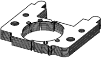
Fig. 1 illustrates the motor according to exemplary embodiment of the present utility model.As shown in fig. 1, stator core 1 is formed by the main iron core 1a that comprises the first segment core 1b, the second segment core 1c and plate body 1e and the 3rd segment core (I shaped iron core) 1d.The rotor (not shown) is arranged in the rotor insertion hole (not shown) of stator core 1.The output shaft 2 of rotor is by bearing unit 3 supportings.The part of winding, circuit layout card and the power supply connector 4 of the excitation division of resin-formed body 4a covering motor.In this exemplary embodiment, resin-formed body 4a also covers the part of the 3rd segment core (I shaped iron core) 1d.
Rotating vanes etc. are arranged near the tip of output shaft 2, and consist of air blast etc.
Fig. 2 A and Fig. 2 B illustrate the state of the main iron core 1a that is formed by the first segment core 1b of the present utility model, the second segment core 1c and plate body 1e.The first segment core 1b and the second segment core 1c are installed between two plate body 1e to consist of main iron core 1a, and notch 12 and rotor insertion hole 12a are set.In Fig. 2 A and Fig. 2 B, the first segment core 1b has the first shank 1fb and the first semicircle curved tooth section, and the second segment core 1c has the second shank 1fc and the second semicircle curved tooth section.By the first shank 1fb of the first segment core 1b and the second shank 1fc of the second segment core 1c are arranged along equidirectional, and two tips of the tooth section by making the first segment core 1b are closely in the face of two tips of the tooth section of the second segment core 1c, and form notch 12.Plate body 1e bridge joint notch, and be stacked on the first segment core 1b and the second segment core 1c, make two segment cores be installed between plate body 1e.
As segment core and plate body, use the laminated body of being made by magnetic materials such as electromagnetic steel plates.When the first segment core 1b and the second segment core 1c were installed between two plate body 1e integrated formation main iron core 1a, electromagnetic steel plate was provided with the part that interweaves etc. and fixing by riveted joint.The end face of electromagnetic steel plate can partly be welded to one another and be integral.Alternatively, electromagnetic steel plate can be integral by binding agent is bonded to one another.
This structure can be also the first segment core 1b to be divided into two-layer, the second segment core 1c is divided into two-layer, and plate body 1e is installed between each layer of the first segment core 1b and the second segment core 1c.
Fig. 3 A illustrates the state of the first segment core 1b and the second segment core 1c, and Fig. 3 B illustrates the state of plate body 1e, and Fig. 3 C illustrates the state of the 3rd segment core 1d.Stator core 1 is by making the first segment core 1b, the second segment core 1c, the 3rd segment core 1d and plate body 1e is integrated consists of.Then, rotor insertion hole 12a is described.The hole shape of rotor insertion hole 12a is to be that circular arc 5 and circular arc 6 consist of by two the different circular arcs that interconnect smoothly.The shape of circular arc 5 is parts of the circular arc centered by the center of rotor of output shaft axle.The shape of circular arc 6 is parts of the circular arc centered by the position that separates by the center with rotor of output shaft axle.Then, circular arc 5 and circular arc 6 following layout in rotor insertion hole 12a.For this exemplary embodiment is described, rotor insertion hole 12a is divided into first quartile to fourth quadrant.Circular arc 5 is arranged in the first quartile and third quadrant of rotor insertion hole 12a, and circular arc 6 is arranged in the second quadrant and fourth quadrant of rotor insertion hole 12a.The center of circular arc 6 is in the position that the center with rotor of output shaft axle separates, but this distance of separation is set in the scope that circular arc 5 and circular arc 6 interconnect smoothly.
Because the hole shape of rotor insertion hole 12a is made of circular arc 5 and circular arc 6, therefore can obtain following structure, that is, when the driving of motor stopped, the position of the position of notch 12 and the utmost point of rotor is inconsistent was not constant, namely stop position magnetically moves.
As shown in Fig. 2 A and Fig. 2 B, plate body 1e with shape of bridge joint notch is stacked on the superiors' side and the orlop side of stator core 1, the first segment core 1b and the second segment core 1c are arranged in the left and right sides of each accompanying drawing, and the superiors' side of notch 12 and orlop side are by plate body 1e bridge joint.This structure can improve the dimensional accuracy of hole shape of the rotor insertion hole 12a of stator core 1, and can further dwindle the gap between rotor insertion hole 12a and rotor.
The leg side of the joint portion that the first shank 1fb of the first segment core 1b, the second shank 1fc of the second segment core 1c and the 3rd segment core (I shaped iron core) 1d combine has protruding 1gb and 1gc, and the 3rd segment core side has depression 1h.The shape of the faying face of projection 1gb, 1gc and depression 1h is watched from the stacking direction of segment core and is essentially circular, and each protruding root has neck, and neck is bonded to the protuberance at the tip of depression.
The depression 1h of the 3rd segment core (I shaped iron core) 1d also is used for when resin-formed body 4a moulding, resin-formed body 4a being positioned mould.Depression 1h has dimensional accuracy round-shaped of easy raising mould.The shape of the 3rd segment core 1d can be bar-shaped.
Then, as shown in Fig. 4 A and Fig. 4 B, single-phase winding is wrapped on the bobbin 14 of being made by insulating material, thereby consists of bobbin winding body 15.The 3rd segment core (I shaped iron core) 1d inserts in bobbin winding body 15 with excitation section 16.Terminal 14a is arranged on the part of bobbin 14, and single-phase winding is connected in terminal 14a.
Excitation division 16 and power supply connector 4 are arranged on circuit layout card 17, and by with the terminal soldering of terminal 14a and power supply connector 4 circuit layout card to circuit layout card 17, terminal 14a are electrically connected to the terminal of power supply connector 4.The terminal of the opposite side of power supply connector 4 or lead-in wire are connected in outside power suppling part.
In the present embodiment, excitation division 16 and power supply connector 4 are arranged on circuit layout card 17, with each terminal soldering to circuit layout card, then the part of excitation division 16, circuit layout card 17 and power supply connector 4 covers with resin-formed body 4a at least, thereby consists of stationary part assembly 18.Main iron core 1a, rotor and bearing unit 3 are combined with stationary part assembly 18 complete motor.Here, as each terminal, suitably select make and have the bar-shaped square pin of square cross section basically or have the bar-shaped pin of circular cross section by conducting metal.
As the material of the heart yearn of the winding winding in motor of the present utility model, can use and contain the alloy of copper and aluminium at least, perhaps contain the aluminum or aluminum alloy of trace impurity.
As the material of the resin-formed body in motor of the present utility model, can use any of thermosetting resin and thermoplastic resin.For example, as resin-formed body, can suitably select unsaturated polyester resin, phenolic resins or the epoxy resin of thermosetting resin.As resin-formed body, also can suitably select pet resin or the polybutylene terephthalate (PBT) resin of thermoplastic resin.
When motor of the present utility model is arranged on equipment, form motor unit, it has the fixture that carries out equipment installation use by the buffer in the protuberance that inserts the approaching bearing unit of output shaft.Form air blast by from the most advanced and sophisticated side of the output shaft of motor unit, rotating vane being installed.
Rotor of the present utility model is by being cylindrically to consist of plastics magnetic forming materials, and has a plurality of N magnetic poles and S magnetic pole in periphery.Yet, as the structure of rotor, can select the structure except said structure.
In structure of the present utility model, pair of bearings unit 3 supporting rotors and main iron core 1a are installed in this between bearing unit 3, and the first segment core 1b and the second segment core 1c are installed between two plate body 1e the main iron core 1a with being integrally formed.Therefore, even the dimensional accuracy of bearing unit 3 grades reduces and the bearing unit distortion, the position of the first segment core 1b and the second segment core 1c still keeps stable.
Therefore, reduce the variation of the magnetic circuit of motor, thereby reduced the variation of motor characteristic.The reduction of the variation of motor characteristic further helps to install the stability of the equipment of motor, and larger industrial value is provided.
Eccentric or the inclination of motor output shaft is suppressed, and can reduce the variation of motor characteristic.
If have torsional strain in the structure middle (center) bearing unit 3 that separates with the second segment core 1c without plate body 1e and the first segment core 1b, correct distortion from the normal position due to the strain of bearing unit 3 by the position of installation shaft bearing unit 3, the first segment core 1b and the second segment core 1c so.If in the situation that bearing unit 3 fixed by screw thread, improper and bearing unit 3 distortion in the position that spins of bolt, distortion is corrected in the position of the first segment core 1b and the second segment core 1c from the normal position so.The utility model can reduce the frequency that these faults occur.
Motor of the present utility model can have the structure that the grounding parts of the electric equipment that motor is installed is electrically connected to the main iron core of motor.Increasing this structure is in order to satisfy motor of the present utility model and the required specification of electric equipment side that motor is installed.
Industrial usability
Motor of the present utility model can suppress the eccentric of motor output shaft or tilt, and is therefore useful for the drive motor that is arranged on the air blast on electric equipment.
Reference numerals list:
1, stator core
1a, main iron core
1b, the first segment core
1c, the second segment core
1e, plate body
1d, the 3rd segment core (I shaped iron core)
2, output shaft
3, bearing unit
4, power supply connector (lead assemblies)
4a, resin-formed body
5, circular arc (part of the inside diameter of rotor insertion hole)
6, circular arc (part of the inside diameter of rotor insertion hole)
12, notch
12a, rotor insertion hole
14, bobbin
15, bobbin winding body
16, excitation division
17, circuit layout card
18, stationary part assembly
101, stator
102, rotor
103, bearing unit
104, terminal
105, iron core internal diameter
106, iron core recess internal diameter.