CN116229713A - A spatial alignment method and system for vehicle-road coordination - Google Patents
A spatial alignment method and system for vehicle-road coordination Download PDFInfo
- Publication number
- CN116229713A CN116229713A CN202310090952.6A CN202310090952A CN116229713A CN 116229713 A CN116229713 A CN 116229713A CN 202310090952 A CN202310090952 A CN 202310090952A CN 116229713 A CN116229713 A CN 116229713A
- Authority
- CN
- China
- Prior art keywords
- coordinate system
- vehicle
- camera
- subsystem
- lidar
- Prior art date
- Legal status (The legal status is an assumption and is not a legal conclusion. Google has not performed a legal analysis and makes no representation as to the accuracy of the status listed.)
- Pending
Links
Images


Classifications
-
- G—PHYSICS
- G08—SIGNALLING
- G08G—TRAFFIC CONTROL SYSTEMS
- G08G1/00—Traffic control systems for road vehicles
- G08G1/01—Detecting movement of traffic to be counted or controlled
- G08G1/0104—Measuring and analyzing of parameters relative to traffic conditions
- G08G1/0125—Traffic data processing
-
- G—PHYSICS
- G01—MEASURING; TESTING
- G01S—RADIO DIRECTION-FINDING; RADIO NAVIGATION; DETERMINING DISTANCE OR VELOCITY BY USE OF RADIO WAVES; LOCATING OR PRESENCE-DETECTING BY USE OF THE REFLECTION OR RERADIATION OF RADIO WAVES; ANALOGOUS ARRANGEMENTS USING OTHER WAVES
- G01S19/00—Satellite radio beacon positioning systems; Determining position, velocity or attitude using signals transmitted by such systems
- G01S19/38—Determining a navigation solution using signals transmitted by a satellite radio beacon positioning system
- G01S19/39—Determining a navigation solution using signals transmitted by a satellite radio beacon positioning system the satellite radio beacon positioning system transmitting time-stamped messages, e.g. GPS [Global Positioning System], GLONASS [Global Orbiting Navigation Satellite System] or GALILEO
- G01S19/42—Determining position
-
- G—PHYSICS
- G06—COMPUTING OR CALCULATING; COUNTING
- G06T—IMAGE DATA PROCESSING OR GENERATION, IN GENERAL
- G06T7/00—Image analysis
- G06T7/20—Analysis of motion
- G06T7/246—Analysis of motion using feature-based methods, e.g. the tracking of corners or segments
-
- G—PHYSICS
- G06—COMPUTING OR CALCULATING; COUNTING
- G06T—IMAGE DATA PROCESSING OR GENERATION, IN GENERAL
- G06T7/00—Image analysis
- G06T7/70—Determining position or orientation of objects or cameras
- G06T7/73—Determining position or orientation of objects or cameras using feature-based methods
-
- G—PHYSICS
- G06—COMPUTING OR CALCULATING; COUNTING
- G06T—IMAGE DATA PROCESSING OR GENERATION, IN GENERAL
- G06T7/00—Image analysis
- G06T7/80—Analysis of captured images to determine intrinsic or extrinsic camera parameters, i.e. camera calibration
-
- G—PHYSICS
- G08—SIGNALLING
- G08G—TRAFFIC CONTROL SYSTEMS
- G08G1/00—Traffic control systems for road vehicles
- G08G1/01—Detecting movement of traffic to be counted or controlled
- G08G1/0104—Measuring and analyzing of parameters relative to traffic conditions
- G08G1/0108—Measuring and analyzing of parameters relative to traffic conditions based on the source of data
- G08G1/0112—Measuring and analyzing of parameters relative to traffic conditions based on the source of data from the vehicle, e.g. floating car data [FCD]
-
- G—PHYSICS
- G08—SIGNALLING
- G08G—TRAFFIC CONTROL SYSTEMS
- G08G1/00—Traffic control systems for road vehicles
- G08G1/01—Detecting movement of traffic to be counted or controlled
- G08G1/0104—Measuring and analyzing of parameters relative to traffic conditions
- G08G1/0108—Measuring and analyzing of parameters relative to traffic conditions based on the source of data
- G08G1/0116—Measuring and analyzing of parameters relative to traffic conditions based on the source of data from roadside infrastructure, e.g. beacons
-
- G—PHYSICS
- G08—SIGNALLING
- G08G—TRAFFIC CONTROL SYSTEMS
- G08G1/00—Traffic control systems for road vehicles
- G08G1/01—Detecting movement of traffic to be counted or controlled
- G08G1/0104—Measuring and analyzing of parameters relative to traffic conditions
- G08G1/0137—Measuring and analyzing of parameters relative to traffic conditions for specific applications
-
- G—PHYSICS
- G06—COMPUTING OR CALCULATING; COUNTING
- G06T—IMAGE DATA PROCESSING OR GENERATION, IN GENERAL
- G06T2207/00—Indexing scheme for image analysis or image enhancement
- G06T2207/10—Image acquisition modality
- G06T2207/10032—Satellite or aerial image; Remote sensing
- G06T2207/10044—Radar image
-
- G—PHYSICS
- G06—COMPUTING OR CALCULATING; COUNTING
- G06T—IMAGE DATA PROCESSING OR GENERATION, IN GENERAL
- G06T2207/00—Indexing scheme for image analysis or image enhancement
- G06T2207/30—Subject of image; Context of image processing
- G06T2207/30241—Trajectory
-
- G—PHYSICS
- G06—COMPUTING OR CALCULATING; COUNTING
- G06T—IMAGE DATA PROCESSING OR GENERATION, IN GENERAL
- G06T2207/00—Indexing scheme for image analysis or image enhancement
- G06T2207/30—Subject of image; Context of image processing
- G06T2207/30248—Vehicle exterior or interior
- G06T2207/30252—Vehicle exterior; Vicinity of vehicle
-
- Y—GENERAL TAGGING OF NEW TECHNOLOGICAL DEVELOPMENTS; GENERAL TAGGING OF CROSS-SECTIONAL TECHNOLOGIES SPANNING OVER SEVERAL SECTIONS OF THE IPC; TECHNICAL SUBJECTS COVERED BY FORMER USPC CROSS-REFERENCE ART COLLECTIONS [XRACs] AND DIGESTS
- Y02—TECHNOLOGIES OR APPLICATIONS FOR MITIGATION OR ADAPTATION AGAINST CLIMATE CHANGE
- Y02D—CLIMATE CHANGE MITIGATION TECHNOLOGIES IN INFORMATION AND COMMUNICATION TECHNOLOGIES [ICT], I.E. INFORMATION AND COMMUNICATION TECHNOLOGIES AIMING AT THE REDUCTION OF THEIR OWN ENERGY USE
- Y02D30/00—Reducing energy consumption in communication networks
- Y02D30/70—Reducing energy consumption in communication networks in wireless communication networks
Landscapes
- Engineering & Computer Science (AREA)
- Physics & Mathematics (AREA)
- General Physics & Mathematics (AREA)
- Chemical & Material Sciences (AREA)
- Analytical Chemistry (AREA)
- Computer Vision & Pattern Recognition (AREA)
- Theoretical Computer Science (AREA)
- Radar, Positioning & Navigation (AREA)
- Remote Sensing (AREA)
- Multimedia (AREA)
- Computer Networks & Wireless Communication (AREA)
- Traffic Control Systems (AREA)
Abstract
Description
技术领域technical field
本发明涉及智能交通技术领域,尤其是涉及一种用于车路协同的空间对齐方法及系统。The invention relates to the technical field of intelligent transportation, in particular to a spatial alignment method and system for vehicle-road coordination.
背景技术Background technique
车路协同技术是道路行车安全方面的重要支撑技术,也是实现智能交通的基础研究问题。当前,很多汽车厂商都在致力于智能交通系统ITS(Intelligent TransportationSystems)的发展,其中智能车路协同关键技术是ITS研究的热点和前沿技术。目前,世界各国正在积极进行车路协同系统方面的研究与实验,并将其作为改善道路交通安全和效率的重要手段。在国外,欧洲汽车公司早已将车联网技术应用于车队的智能化管理。同时,欧洲的客运公司也在积极推广应用车联网技术。美国的IVHS,日本的VICS等系统也都通过车辆与道路之间建立有效的信息通信,从而实现智能交通的管理和信息服务。这些信息服务虽然侧重点各有不同,但都是以车路协同技术为基础。Vehicle-road coordination technology is an important supporting technology for road safety, and it is also a basic research issue for realizing intelligent transportation. At present, many automobile manufacturers are committed to the development of intelligent transportation system ITS (Intelligent Transportation Systems), among which the key technology of intelligent vehicle road coordination is the hot spot and cutting-edge technology of ITS research. At present, countries around the world are actively conducting research and experiments on the vehicle-road coordination system, and regard it as an important means to improve road traffic safety and efficiency. In foreign countries, European automobile companies have already applied the Internet of Vehicles technology to the intelligent management of fleets. At the same time, European passenger transport companies are also actively promoting the application of Internet of Vehicles technology. Systems such as IVHS in the United States and VICS in Japan also establish effective information communication between vehicles and roads, thereby realizing intelligent traffic management and information services. Although these information services have different focuses, they are all based on vehicle-road coordination technology.
车路协同系统由“先进的车”和“智慧的路”来支持,通过通信平台实现车路云一体化建设,满足车路协同的各种应用需求。“先进的车”是指安装有传感设备的智能汽车,但是单车智能的感知精度和感知范围有限,比如受公交车遮挡的行人;而“智慧的路”是通过安装在路侧的各类先进传感器,通过收集和共享道路和交通参与者的实时信息,由于路侧传感器安装位置较高,可以近似提供宽阔的视野,从而弥补车端传感设备的盲区;此外,路侧还可以部署边缘云来降低车载端的感知成本。通过车路协同感知,可以大大增加车辆的感知范围和感知能力,进而有利于减少交通事故,保障公路中交通参与者的人身安全和财产安全,并且避免道路拥塞,改善交通运输环境。在开展车路协同感知融合之前,需要先进行车路空间对齐,把车载和路侧感知到的信息放在统一的坐标系下进行融合。如果没有进行空间对齐,将车、路感知到的目标或轨迹进行关联时容易产生误差,影响融合效果。The vehicle-road coordination system is supported by "advanced vehicles" and "smart roads", and realizes the integrated construction of vehicle-road cloud through the communication platform to meet various application requirements of vehicle-road coordination. "Advanced vehicles" refer to smart cars equipped with sensing equipment, but the perception accuracy and range of single-vehicle intelligence are limited, such as pedestrians blocked by buses; while "smart roads" Advanced sensors collect and share real-time information on roads and traffic participants. Due to the high installation position of roadside sensors, they can approximately provide a wide field of vision, thereby making up for the blind spots of vehicle-end sensing equipment; in addition, edge sensors can also be deployed on the roadside Cloud to reduce the perceived cost of the vehicle. Through vehicle-road collaborative sensing, the sensing range and sensing ability of vehicles can be greatly increased, which in turn helps to reduce traffic accidents, protect the personal safety and property safety of traffic participants on the highway, avoid road congestion, and improve the transportation environment. Before carrying out the vehicle-road collaborative perception fusion, it is necessary to align the vehicle-road space first, and integrate the information sensed by the vehicle and the roadside in a unified coordinate system. If there is no spatial alignment, errors will easily occur when associating the objects or trajectories perceived by the car and road, which will affect the fusion effect.
发明内容Contents of the invention
本发明的目的就是为了克服上述现有技术存在的缺陷而提供了一种用于车路协同的空间对齐方法及系统,保证了车路协同系统在信息融合过程中空间对齐,为车路协同感知构建统一坐标系,提高了感知目标物的定位和跟踪精度。The purpose of the present invention is to provide a spatial alignment method and system for vehicle-road coordination in order to overcome the above-mentioned defects in the prior art, to ensure the spatial alignment of the vehicle-road coordination system during the information fusion process, and to provide a vehicle-road collaborative perception Construct a unified coordinate system to improve the positioning and tracking accuracy of the perceived target.
本发明的目的可以通过以下技术方案来实现:The purpose of the present invention can be achieved through the following technical solutions:
根据本发明的第一方面,提供了一种用于车路协同的空间对齐方法,该方法包括以下步骤:According to the first aspect of the present invention, a spatial alignment method for vehicle-road coordination is provided, the method includes the following steps:
步骤S1、分别在路侧、车端部署智能网联路侧子系统、智能网联车载子系统,其中,子系统间通过V2X进行车路协同;Step S1. Deploy the intelligent networked roadside subsystem and the intelligent networked vehicle subsystem on the roadside and the vehicle respectively, wherein the vehicle-road coordination is carried out between the subsystems through V2X;
步骤S2、智能网联路侧子系统和智能网联车载子系统分别通过构建大地WGS84坐标系进行子系统间的空间对齐;Step S2, the intelligent network-connected roadside subsystem and the intelligent network-connected vehicle-mounted subsystem respectively carry out the spatial alignment between the subsystems by constructing the earth WGS84 coordinate system;
步骤S3、智能网联路侧子系统构建东北天坐标系进行路侧子系统内部的空间对齐,然后将东北天坐标系转换到大地WGS84坐标系;Step S3, the intelligent network-connected roadside subsystem constructs the northeast sky coordinate system for spatial alignment inside the roadside subsystem, and then converts the northeast sky coordinate system to the earth WGS84 coordinate system;
步骤S4、智能网联车载子系统构建东北天坐标系进行车载子系统内部的空间对齐,然后基于车载GPS/北斗将东北天坐标系转换到大地WGS84坐标系。Step S4. The intelligent networked vehicle subsystem constructs the northeast sky coordinate system for spatial alignment inside the vehicle subsystem, and then converts the northeast sky coordinate system to the earth WGS84 coordinate system based on the vehicle GPS/Beidou.
优选地,所述智能网联路侧子系统包括集成在一起的路侧感知设备、路侧计算设备和路侧通信设备;所述路侧感知设备包括摄像头、激光雷达和毫米波雷达。Preferably, the intelligent networked roadside subsystem includes integrated roadside sensing equipment, roadside computing equipment, and roadside communication equipment; the roadside sensing equipment includes cameras, laser radars, and millimeter-wave radars.
优选地,所述智能网联车载子系统包括集成在一起的GPS/北斗模块、车载感知设备、车载计算设备和车载通信设备;所述车载感知设备包括摄像头、激光雷达和毫米波雷达。Preferably, the intelligent internet-connected vehicle subsystem includes an integrated GPS/Beidou module, a vehicle perception device, a vehicle computing device and a vehicle communication device; the vehicle perception device includes a camera, a laser radar and a millimeter wave radar.
优选地,所述毫米波雷达、超声波雷达、激光雷达和摄像头对应的空间对齐过程分别为:Preferably, the spatial alignment processes corresponding to the millimeter-wave radar, ultrasonic radar, lidar and camera are respectively:
毫米波雷达:从毫米波雷达坐标系转换到东北天坐标系,具体为:将毫米波雷达固定安装在路侧,通过毫米波雷达外参标定将毫米波雷达坐标系转换到东北天坐标系;Millimeter-wave radar: convert from the millimeter-wave radar coordinate system to the northeast sky coordinate system, specifically: install the millimeter-wave radar on the roadside, and convert the millimeter-wave radar coordinate system to the northeast sky coordinate system through the calibration of the millimeter-wave radar external parameters;
激光雷达:从激光雷达坐标系转换到东北天坐标系,具体为:将激光雷达固定安装在路侧,使指南针方向朝向激光雷达坐标系中X轴方向并记录坐标系夹角θ,并采用最小二乘法求取激光雷达三维点云坐标系到东北天坐标系的转换矩阵;Lidar: Convert from the Lidar coordinate system to the Northeast sky coordinate system, specifically: fix the Lidar on the roadside, make the compass direction point to the X-axis in the Lidar coordinate system and record the angle θ of the coordinate system, and use the minimum Calculate the transformation matrix from the three-dimensional point cloud coordinate system of the lidar to the northeast sky coordinate system by the square multiplication method;
摄像头:先对相机进行内参标定,然后通过联合标定由像素坐标系转换到激光雷达坐标系,再从激光雷达坐标系转换到东北天坐标系。Camera: first perform internal reference calibration on the camera, then convert from the pixel coordinate system to the lidar coordinate system through joint calibration, and then convert from the lidar coordinate system to the northeast sky coordinate system.
优选地,所述对相机进行内参标定,具体为:Preferably, the internal reference calibration of the camera is specifically:
1)构建相机成像模型,数学表达式为:1) Construct the camera imaging model, the mathematical expression is:

式中,(U,V,W)为在世界坐标系下某点的物理坐标,(u,v)为(U,V,W)对应的在像素坐标系下的像素坐标,Z为尺度因子;
2)采集待标定相机的棋盘格标定板的图片,利用相机内参标定原理计算出相机内参矩阵和畸变系数。2) Collect the picture of the checkerboard calibration board of the camera to be calibrated, and use the camera internal reference calibration principle to calculate the camera internal reference matrix and distortion coefficient.
优选地,所述通过联合标定由像素坐标系转换到激光雷达坐标系,包括以下子步骤:Preferably, said conversion from pixel coordinate system to lidar coordinate system through joint calibration includes the following sub-steps:
1)在相机和激光雷达共视区内放置标记物,采集标定数据:1) Place markers in the common viewing area of the camera and lidar, and collect calibration data:
2)分别获取标记物在相机中的像素坐标、在激光雷达点云中的坐标;2) Obtain the pixel coordinates of the marker in the camera and the coordinates in the lidar point cloud respectively;
3)采用位姿算法求解激光雷达坐标系到相机坐标系的转换矩阵;3) Use the pose algorithm to solve the transformation matrix from the lidar coordinate system to the camera coordinate system;
4)提取点云路面数,并对路面点云进行分区,然后对每个点云分区进行拟合,对路面点云进行上采样,生成点云-像素坐标点对;4) Extract the point cloud road surface number, and partition the road surface point cloud, then fit each point cloud partition, upsample the road surface point cloud, and generate point cloud-pixel coordinate point pairs;
5)采用生成的点云-像素坐标点对做数据集,采用人工智能算法进行三维点云坐标的多元回归预测,将像素坐标转换到点云坐标;5) Use the generated point cloud-pixel coordinate point pairs as a data set, use artificial intelligence algorithms to perform multiple regression prediction of 3D point cloud coordinates, and convert pixel coordinates to point cloud coordinates;
6)基于激光雷达坐标系到东北天坐标系的转换,将像素坐标到东北天坐标的转换。6) Based on the transformation from the lidar coordinate system to the northeast sky coordinate system, the pixel coordinates are converted to the northeast sky coordinates.
优选地,所述步骤3)具体为:采用EPnP算法求解激光雷达坐标系到相机坐标系的转换矩阵。Preferably, the step 3) specifically includes: solving the conversion matrix from the lidar coordinate system to the camera coordinate system by using the EPnP algorithm.
优选地,所述步骤5)中的人工智能方法包括决策树和随机森林。Preferably, the artificial intelligence method in step 5) includes decision tree and random forest.
优选地,所述步骤S3或S4中将东北天坐标系转换到大地WGS84坐标系,转换表达式为:Preferably, in the step S3 or S4, the northeast sky coordinate system is converted to the earth WGS84 coordinate system, and the conversion expression is:


式中,(x,y)为东北天坐标系中任意点坐标,(lat1,lon1)为(x,y)在WGS84坐标系下的经纬度,(lat0,lon0)为东北天坐标系原点的经纬度,R为地球半径。In the formula, (x, y) is the coordinate of any point in the northeast sky coordinate system, (lat 1 , lon 1 ) is the longitude and latitude of (x, y) in the WGS84 coordinate system, (lat 0 , lon 0 ) is the northeast sky coordinate The latitude and longitude of the origin, R is the radius of the earth.
根据本发明的第二方面,提供了一种用于车路协同的空间对齐系统,该系统包括:According to the second aspect of the present invention, a space alignment system for vehicle-road coordination is provided, the system includes:
设置于路侧的智能网联路侧子系统、设置于车辆上的智能网联车载子系统,且智能网联车载子系统和智能网联路侧子系统通过V2X进行车路协同;The intelligent networked roadside subsystem installed on the roadside, the intelligent networked vehicle subsystem installed on the vehicle, and the intelligent networked vehicle subsystem and the intelligent networked roadside subsystem perform vehicle-road coordination through V2X;
其中,车路协同过程中采用任一项所述的方法进行空间对齐。Wherein, the method described in any one is used for spatial alignment in the vehicle-road coordination process.
与现有技术相比,本发明具有以下优点:Compared with the prior art, the present invention has the following advantages:
1)针对车路协同对时空同步的需要所设计的,通过空间对齐机制,即使针对不同的子系统,如车载子系统或路侧子系统,也能够获取到各个目标物在统一坐标系下的位置状态,为基于位置点的车路协同融合创造了有利条件,保证了车路协同系统在信息融合过程中空间上的对齐,可以为车路协同感知构建统一的坐标系,从而有助于提高感知目标物的定位和跟踪精度;1) Designed for the need of time-space synchronization for vehicle-road coordination, through the spatial alignment mechanism, even for different subsystems, such as vehicle-mounted subsystems or roadside subsystems, the coordinates of each target object in a unified coordinate system can be obtained The location state creates favorable conditions for the vehicle-road collaborative fusion based on the location point, ensures the spatial alignment of the vehicle-road collaborative system in the process of information fusion, and can build a unified coordinate system for the vehicle-road collaborative perception, thereby helping to improve Perceive the positioning and tracking accuracy of the target;
2)本发明针对不同感知设备分别建立东北天坐标系,并通过联合标定法,提高了位置坐标转换的准确性;2) The present invention establishes the northeast sky coordinate system respectively for different sensing devices, and improves the accuracy of position coordinate conversion through the joint calibration method;
3)本发明采用人工智能算法实现三维点云到图像像素的映射,使得空间对齐的准确性更高;3) The present invention adopts artificial intelligence algorithm to realize the mapping of three-dimensional point cloud to image pixel, so that the accuracy of spatial alignment is higher;
4)本发明还可进一步扩展到车、路、云一体化系统,可扩展性强、实用性高。4) The present invention can be further extended to an integrated vehicle, road, and cloud system, which has strong scalability and high practicability.
附图说明Description of drawings
图1为根据本发明的用于车路协同的空间对齐方法及系统的架构图;FIG. 1 is a structural diagram of a spatial alignment method and system for vehicle-road coordination according to the present invention;
图2为根据本发明的用于车路协同的空间对齐方法及系统的智能网联路侧子系统的架构图;FIG. 2 is a structural diagram of the intelligent network roadside subsystem of the spatial alignment method and system for vehicle-road coordination according to the present invention;
图3为根据本发明的用于车路协同的空间对齐方法及系统的激光雷达点云上采样过程;Fig. 3 is the upsampling process of the laser radar point cloud according to the spatial alignment method and system for vehicle-road coordination according to the present invention;
图4为根据本发明的用于车路协同的空间对齐方法及系统的雷达坐标系到东北天坐标系转换的示意图;4 is a schematic diagram of the conversion from the radar coordinate system to the northeast sky coordinate system according to the spatial alignment method and system for vehicle-road coordination according to the present invention;
图5为根据本发明的用于车路协同的空间对齐方法及系统的棋盘格采集示意图;其中,图5a和5b分别不同角度采集示意图。Fig. 5 is a schematic diagram of checkerboard acquisition according to the spatial alignment method and system for vehicle-road coordination according to the present invention; wherein, Fig. 5a and Fig. 5b are respectively different angle acquisition diagrams.
具体实施方式Detailed ways
下面将结合本发明实施例中的附图,对本发明实施例中的技术方案进行清楚、完整地描述,显然,所描述的实施例是本发明的一部分实施例,而不是全部实施例。基于本发明中的实施例,本领域普通技术人员在没有做出创造性劳动的前提下所获得的所有其他实施例,都应属于本发明保护的范围。The following will clearly and completely describe the technical solutions in the embodiments of the present invention with reference to the drawings in the embodiments of the present invention. Obviously, the described embodiments are part of the embodiments of the present invention, not all of them. Based on the embodiments of the present invention, all other embodiments obtained by persons of ordinary skill in the art without making creative efforts shall fall within the protection scope of the present invention.
实施例Example
参照图1-5,本实施例给出了一种用于车路协同的空间对齐系统,该系统包括:设置于路侧的智能网联路侧子系统和设置于车辆上的智能网联车载子系统,且智能网联路侧子系统和智能网联车载子系统通过V2X集成起来的车路协同系统。作为优选的技术方案,该车路协同系统可进一步扩展到车、路、云一体化系统。Referring to Figures 1-5, this embodiment presents a spatial alignment system for vehicle-road coordination, which includes: an intelligent networked roadside subsystem installed on the roadside and an intelligent networked vehicle-mounted subsystem installed on the vehicle subsystem, and the vehicle-road coordination system that integrates the intelligent network roadside subsystem and the intelligent network vehicle subsystem through V2X. As a preferred technical solution, the vehicle-road coordination system can be further extended to an integrated vehicle, road, and cloud system.
智能网联路侧子系统包括有路侧感知设备、路侧计算设备和路侧通信设备,其中:路侧计算设备包括MEC服务器、工控机和电脑,路侧感知设备包括摄像头、激光雷达、毫米波雷达或其它传感器如微波雷达,路侧通信设备包括5G/4G基站、V2X RSU;The intelligent network roadside subsystem includes roadside sensing equipment, roadside computing equipment and roadside communication equipment, among which: roadside computing equipment includes MEC server, industrial computer and computer, roadside sensing equipment includes cameras, laser radar, millimeter Wave radar or other sensors such as microwave radar, roadside communication equipment including 5G/4G base stations, V2X RSU;
路侧感知设备、路侧计算设备和路侧通信设备之间通过路由器、交换机或点到点网络集成起来,其空间对齐过程为如图2所示,针对毫米波雷达,从毫米波雷达坐标系转换到东北天坐标系,微波雷达同毫米波雷达一样;针对激光雷达,从激光雷达坐标系转换到东北天坐标系;针对摄像头,先对相机进行内参标定,然后通过联合标定由像素坐标系转换到激光雷达坐标系,再从激光雷达坐标系转换到东北天坐标系。Roadside sensing devices, roadside computing devices, and roadside communication devices are integrated through routers, switches, or point-to-point networks. The spatial alignment process is shown in Figure 2. For millimeter-wave radar, from the millimeter-wave radar coordinate system Convert to the northeast sky coordinate system, the microwave radar is the same as the millimeter-wave radar; for the lidar, convert from the lidar coordinate system to the northeast sky coordinate system; for the camera, first perform internal reference calibration on the camera, and then convert from the pixel coordinate system through joint calibration To the lidar coordinate system, and then convert from the lidar coordinate system to the northeast sky coordinate system.
智能网联车载子系统包括含有兼容北斗/GPS的GNSS模块,以及集成RTK和IMU的组合导航定位系统,车载感知设备、车载计算设备及车载通信设备;其中GPS/北斗含有RTK高精度定位。The intelligent networked vehicle subsystem includes a GNSS module compatible with Beidou/GPS, a combined navigation and positioning system integrating RTK and IMU, vehicle-mounted perception equipment, vehicle-mounted computing equipment, and vehicle-mounted communication equipment; GPS/Beidou includes RTK high-precision positioning.
车载计算设备包括嵌入式控制器与工控机,车载通信设备包括5G/4G CPE、V2XOBU;Vehicle-mounted computing equipment includes embedded controllers and industrial computers, and vehicle-mounted communication equipment includes 5G/4G CPE and V2XOBU;
车载感知设备包括摄像头、激光雷达、毫米波雷达或其它传感器如超声波雷达;其空间对齐过程为:针对毫米波雷达,从毫米波雷达坐标系转换到东北天坐标系;针对超声波雷达,从超声波雷达坐标系转换到东北天坐标系;针对激光雷达,从激光雷达坐标系转换到东北天坐标系;针对摄像头,先对相机进行内参标定,然后通过联合标定由像素坐标系转换到激光雷达坐标系,再从激光雷达坐标系转换到东北天坐标系。Vehicle-mounted perception equipment includes cameras, lidars, millimeter-wave radars, or other sensors such as ultrasonic radars; the spatial alignment process is: for millimeter-wave radars, transform from the millimeter-wave radar coordinate system to the northeast sky coordinate system; for ultrasonic radars, from ultrasonic radar to Convert the coordinate system to the northeast sky coordinate system; for the lidar, convert from the lidar coordinate system to the northeast sky coordinate system; for the camera, first perform internal reference calibration on the camera, and then convert from the pixel coordinate system to the lidar coordinate system through joint calibration, Then convert from the lidar coordinate system to the northeast sky coordinate system.
从激光雷达坐标系转换到东北天坐标系,包括以下步骤:Transform from the lidar coordinate system to the northeast sky coordinate system, including the following steps:
激光雷达坐标系和东北天坐标系之间的转换是三维直角坐标系的刚性变换,转换公式如下:The conversion between the lidar coordinate system and the northeast sky coordinate system is a rigid transformation of the three-dimensional Cartesian coordinate system, and the conversion formula is as follows:

其中,XENU、YENU、ZENU是东北天坐标,XLidar、YLidar、ZLidar是激光雷达坐标。通过对激光雷达进行标定,在得知若干点在两个坐标系中的对应坐标时,即可利用最小二乘法求得该转换矩阵。Among them, X ENU , Y ENU , and Z ENU are the coordinates of the northeast sky, and X Lidar , Y Lidar , and Z Lidar are the coordinates of the lidar. By calibrating the lidar, when the corresponding coordinates of several points in the two coordinate systems are known, the transformation matrix can be obtained by using the least square method.
对相机进行内参标定,包括以下步骤:Calibrate the internal reference of the camera, including the following steps:
相机成像模型可由如下公式描述:The camera imaging model can be described by the following formula:

其中,(U,V,W)为在世界坐标系下某一点的物理坐标,(u,v)为该点对应的在像素坐标系下的像素坐标,Z为尺度因子。Among them, (U, V, W) are the physical coordinates of a certain point in the world coordinate system, (u, v) are the pixel coordinates corresponding to the point in the pixel coordinate system, and Z is the scale factor.
矩阵:matrix:

称为相机的内参矩阵,其中,f为像距,dX,dY分别为X,Y方向上的一个像素在相机感光板上的物理长度(即一个像素在感光板上是多少毫米),uO,vO分别为相机感光板中心在像素坐标系下的坐标,θ表示感光板的横边和纵边之间的角度(90°表示无误差)。It is called the internal reference matrix of the camera, wherein, f is the image distance, dX and dY are respectively the physical length of a pixel on the photosensitive plate of the camera in the X and Y directions (that is, how many millimeters a pixel is on the photosensitive plate), u O , v O are the coordinates of the center of the photosensitive plate of the camera in the pixel coordinate system, and θ represents the angle between the horizontal and vertical sides of the photosensitive plate (90° means no error).
首先制作棋盘格标定板,测量棋盘格中一个格子的尺寸大小;First make a checkerboard calibration board, measure the size of a grid in the checkerboard;
将棋盘格置于相机视野中,不断移动棋盘格,并且保证棋盘格在相机视野的上下左右前后都有出现,且具有不同方向的倾角,拍摄大约30张棋盘格图像,如图5所示;Put the checkerboard in the camera field of view, move the checkerboard continuously, and ensure that the checkerboard appears in the top, bottom, left, right, front, back, and front of the camera field of view, and has inclination angles in different directions. Take about 30 checkerboard images, as shown in Figure 5;
使用Python语言利用张正友标定法对采集的棋盘格图像处理,计算出相机的内参矩阵和畸变系数,并利用求得的畸变系数对图像进行去畸变处理,对比图像去畸变前后的变化,显示图像去畸变后的效果。Use the Python language to process the collected checkerboard image using Zhang Zhengyou’s calibration method, calculate the camera’s internal parameter matrix and distortion coefficient, and use the obtained distortion coefficient to perform de-distortion processing on the image, compare the changes before and after de-distortion of the image, and display the de-distortion of the image. Distorted effect.
通过联合标定由像素坐标系转换到激光雷达坐标系,包括以下步骤:Converting from the pixel coordinate system to the lidar coordinate system through joint calibration includes the following steps:
(1)标定数据采集。在相机和激光雷达共视区内放置标记物,为了能够在点云中清晰分辨出标记物的位置,可以在标记物上贴上高反射率反光条,如贴上高反射率反光条的手持GPS标定杆。用ROS同时记录激光雷达点云数据和图像数据的,在使用EPnP算法求解联合标定参数时,理论上只需要4个特征点即可求解出标定参数,为了减小在采集数据过程中人为和设备原因引入的误差,可采集多于4个特征点用于求解激光雷达和相机的标定参数;(1) Calibration data collection. Markers are placed in the common viewing area of the camera and the lidar. In order to clearly distinguish the position of the marker in the point cloud, a high-reflectivity reflective strip can be attached to the marker, such as a hand-held device with a high-reflectivity reflective strip. GPS calibration rod. When ROS is used to record lidar point cloud data and image data at the same time, when using the EPnP algorithm to solve the joint calibration parameters, theoretically only 4 feature points are needed to solve the calibration parameters. Due to the error introduced by the reason, more than 4 feature points can be collected to solve the calibration parameters of the lidar and camera;
(2)获取标记物在相机中的像素坐标。由于录制的相机数据为ROS格式,首先采用Python编程语言实现从ROS格式的相机数据中提取出图片,以便选择图片中的像素点。获取到图片后,使用C++编程语言实现从图片中提取出像素坐标,使用时,注意准确选择标记物上所贴的反光条的位置,保证提取出的像素点代表真实的标记物所在的位置;(2) Obtain the pixel coordinates of the marker in the camera. Since the recorded camera data is in ROS format, the Python programming language is first used to extract pictures from the camera data in ROS format in order to select the pixels in the picture. After obtaining the picture, use the C++ programming language to extract the pixel coordinates from the picture. When using it, pay attention to accurately select the position of the reflective strip attached to the marker to ensure that the extracted pixels represent the real position of the marker;
(3)获取标记物在激光雷达点云中的坐标。用ROS工具回放采集的激光雷达标定数据,将激光雷达点云数据在Rviz中可视化,由于标记物上的反光条反射率较高,在Rviz中其颜色会与周围颜色明显不同,使用Publish Point工具在点云中选取标记物的位置,提取出标记物在激光雷达点云中的坐标;(3) Obtain the coordinates of the marker in the lidar point cloud. Use the ROS tool to play back the collected lidar calibration data, and visualize the lidar point cloud data in Rviz. Due to the high reflectivity of the reflective strip on the marker, its color will be significantly different from the surrounding color in Rviz. Use the Publish Point tool Select the position of the marker in the point cloud, and extract the coordinates of the marker in the lidar point cloud;
(4)获取到多个特征点在激光雷达坐标系和相机坐标系中的坐标后,使用C++编程语言,利用EPnP算法迭代优化求解激光雷达坐标系到相机坐标系的转换矩阵,计算像素重投影误差,验证标定结果的精确度。(4) After obtaining the coordinates of multiple feature points in the lidar coordinate system and the camera coordinate system, use the C++ programming language to iteratively optimize the EPnP algorithm to solve the conversion matrix from the lidar coordinate system to the camera coordinate system, and calculate the pixel reprojection Error, to verify the accuracy of the calibration results.
(5)提取点云路面数据。将录制的激光雷达点云标定数据在Rviz中可视化,使用Publish Point工具将路面的点云选中,将点云中路面上的坐标记录下来,获取到路面点云数据;(5) Extract point cloud road surface data. Visualize the recorded laser radar point cloud calibration data in Rviz, use the Publish Point tool to select the point cloud of the road surface, record the coordinates on the road surface in the point cloud, and obtain the road surface point cloud data;
(6)对路面点云进行分区。将路面点云数据在Rviz中可视化,调整点云视角,根据路面点云的横截面和路面点云的坐标对点云进行分区,将近似在一个平面的点云区域划为一个点云分区,将整个路面点云划成多个点云分区,并且用Publish Point工具将每个点云分区的角点保存在文件中;(6) Partition the road surface point cloud. Visualize the road surface point cloud data in Rviz, adjust the point cloud perspective, partition the point cloud according to the cross section of the road surface point cloud and the coordinates of the road surface point cloud, and divide the point cloud area approximately in a plane into a point cloud partition, Divide the entire road surface point cloud into multiple point cloud partitions, and use the Publish Point tool to save the corner points of each point cloud partition in a file;
(7)对每个点云分区进行拟合,对路面点云进行上采样。采用Python编程语言实现最小二乘法拟合平面算法,用平面拟合每个点云分区,得到每个点云分区的平面方程后,在x轴和y轴方向上间隔1cm生成一个点,增加点云密度,实现对点云的上采样;(7) Fit each point cloud partition and upsample the road surface point cloud. Use the Python programming language to implement the least squares method to fit the plane algorithm, use the plane to fit each point cloud partition, and after obtaining the plane equation of each point cloud partition, generate a point at an interval of 1cm in the x-axis and y-axis directions, and add points Cloud density, to achieve upsampling of point clouds;
(8)生成点云-像素坐标点对。用C++编程语言实现点云坐标到像素坐标的转换,根据激光雷达-相机联合标定的结果,将点云坐标映射到像素坐标,生成点云-像素坐标点对;(8) Generate point cloud-pixel coordinate point pairs. Use the C++ programming language to realize the conversion from point cloud coordinates to pixel coordinates, and map the point cloud coordinates to pixel coordinates according to the results of lidar-camera joint calibration to generate point cloud-pixel coordinate point pairs;
(9)像素坐标转换到点云坐标。用Python编程语言实现决策树回归或随机森林回归算法,用生成的点云-像素坐标点对做数据集,实现预测三维点云坐标的多元回归,实现像素坐标到点云坐标的转换;(9) Convert pixel coordinates to point cloud coordinates. Use the Python programming language to implement decision tree regression or random forest regression algorithms, use the generated point cloud-pixel coordinate point pairs as a data set, realize multiple regression for predicting 3D point cloud coordinates, and realize the conversion from pixel coordinates to point cloud coordinates;
(10)利用前面的激光雷达坐标系到东北天坐标系的转换,可进一步实现像素坐标到东北天坐标的转换。(10) Using the previous conversion from the lidar coordinate system to the northeast sky coordinate system, the conversion from pixel coordinates to northeast sky coordinates can be further realized.
注意,本发明的实施方案不限于基于EPnP的联合标定,也可以采用三对点估计位姿的P3P、直接线性变换(DLT)、BA(Bundle Adjustment)等方法实现联合标定。Note that the embodiments of the present invention are not limited to joint calibration based on EPnP, and joint calibration can also be achieved by using methods such as P3P, direct linear transformation (DLT), and BA (Bundle Adjustment) to estimate poses of three pairs of points.
智能网联路侧子系统与智能网联车载子系统之间的空间对齐,是通过分别将智能网联路侧子系统、智能网联车载子系统从东北天坐标系转换到WGS84坐标系,包括以下步骤:The spatial alignment between the intelligent networked roadside subsystem and the intelligent networked vehicle subsystem is achieved by converting the intelligent networked roadside subsystem and the intelligent networked vehicle subsystem from the northeast sky coordinate system to the WGS84 coordinate system, including The following steps:
如图4所示,设东北天坐标系原点O的经纬度为latO、lonO,东北天坐标系中某点的坐标为(x′,y′),则此点的WGS84坐标为As shown in Figure 4, suppose the latitude and longitude of the origin O of the northeast sky coordinate system are lat O and lon O , and the coordinates of a point in the northeast sky coordinate system are (x′, y′), then the WGS84 coordinates of this point are
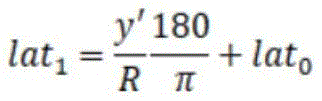

其中,R为地球半径,lat1、lon1为WGS84坐标。Among them, R is the radius of the earth, and lat 1 and lon 1 are WGS84 coordinates.
通过上述公式即可得出激光雷达坐标系中此点的WGS84坐标。The WGS84 coordinates of this point in the lidar coordinate system can be obtained through the above formula.
以上所述,仅为本发明的具体实施方式,但本发明的保护范围并不局限于此,任何熟悉本技术领域的技术人员在本发明揭露的技术范围内,可轻易想到各种等效的修改或替换,这些修改或替换都应涵盖在本发明的保护范围之内。因此,本发明的保护范围应以权利要求的保护范围为准。The above is only a specific embodiment of the present invention, but the protection scope of the present invention is not limited thereto. Any person familiar with the technical field can easily think of various equivalents within the technical scope disclosed in the present invention. Modifications or replacements shall all fall within the protection scope of the present invention. Therefore, the protection scope of the present invention should be based on the protection scope of the claims.
Claims (10)


Priority Applications (1)
| Application Number | Priority Date | Filing Date | Title |
|---|---|---|---|
| CN202310090952.6A CN116229713A (en) | 2023-02-09 | 2023-02-09 | A spatial alignment method and system for vehicle-road coordination |
Applications Claiming Priority (1)
| Application Number | Priority Date | Filing Date | Title |
|---|---|---|---|
| CN202310090952.6A CN116229713A (en) | 2023-02-09 | 2023-02-09 | A spatial alignment method and system for vehicle-road coordination |
Publications (1)
| Publication Number | Publication Date |
|---|---|
| CN116229713A true CN116229713A (en) | 2023-06-06 |
Family
ID=86576231
Family Applications (1)
| Application Number | Title | Priority Date | Filing Date |
|---|---|---|---|
| CN202310090952.6A Pending CN116229713A (en) | 2023-02-09 | 2023-02-09 | A spatial alignment method and system for vehicle-road coordination |
Country Status (1)
| Country | Link |
|---|---|
| CN (1) | CN116229713A (en) |
Cited By (2)
| Publication number | Priority date | Publication date | Assignee | Title |
|---|---|---|---|---|
| CN118226421A (en) * | 2024-05-22 | 2024-06-21 | 山东大学 | LiDAR-Camera Online Calibration Method and System Based on Reflectivity Map |
| CN120088339A (en) * | 2025-02-21 | 2025-06-03 | 武汉大学 | A laser radar and camera joint calibration method and system for spherical space alignment |
Citations (9)
| Publication number | Priority date | Publication date | Assignee | Title |
|---|---|---|---|---|
| CN109631862A (en) * | 2019-01-22 | 2019-04-16 | 青岛秀山移动测量有限公司 | A kind of multi-Sensor Information Fusion Approach of intertidal zone integration mapping |
| CN110927765A (en) * | 2019-11-19 | 2020-03-27 | 博康智能信息技术有限公司 | Laser radar and satellite navigation fused target online positioning method |
| CN111476999A (en) * | 2020-01-17 | 2020-07-31 | 武汉理工大学 | Over-the-horizon sensing system for intelligent networked vehicles based on vehicle-road multi-sensor collaboration |
| US20210063200A1 (en) * | 2019-08-31 | 2021-03-04 | Nvidia Corporation | Map creation and localization for autonomous driving applications |
| CN114187365A (en) * | 2021-12-09 | 2022-03-15 | 联陆智能交通科技(上海)有限公司 | Camera and millimeter wave radar combined calibration method and system for roadside sensing system |
| CN114333298A (en) * | 2021-12-02 | 2022-04-12 | 河北雄安京德高速公路有限公司 | Traffic radar-based vehicle attribution lane estimation method |
| CN114333297A (en) * | 2021-12-02 | 2022-04-12 | 重庆睿行电子科技有限公司 | Traffic radar-based estimation method for vehicle belonging curve lane |
| CN114755662A (en) * | 2022-03-21 | 2022-07-15 | 北京航空航天大学 | Calibration method and device for laser radar and GPS with road-vehicle fusion perception |
| CN115440034A (en) * | 2022-08-24 | 2022-12-06 | 同济大学 | Vehicle-road cooperation realization method and system based on camera |
-
2023
- 2023-02-09 CN CN202310090952.6A patent/CN116229713A/en active Pending
Patent Citations (9)
| Publication number | Priority date | Publication date | Assignee | Title |
|---|---|---|---|---|
| CN109631862A (en) * | 2019-01-22 | 2019-04-16 | 青岛秀山移动测量有限公司 | A kind of multi-Sensor Information Fusion Approach of intertidal zone integration mapping |
| US20210063200A1 (en) * | 2019-08-31 | 2021-03-04 | Nvidia Corporation | Map creation and localization for autonomous driving applications |
| CN110927765A (en) * | 2019-11-19 | 2020-03-27 | 博康智能信息技术有限公司 | Laser radar and satellite navigation fused target online positioning method |
| CN111476999A (en) * | 2020-01-17 | 2020-07-31 | 武汉理工大学 | Over-the-horizon sensing system for intelligent networked vehicles based on vehicle-road multi-sensor collaboration |
| CN114333298A (en) * | 2021-12-02 | 2022-04-12 | 河北雄安京德高速公路有限公司 | Traffic radar-based vehicle attribution lane estimation method |
| CN114333297A (en) * | 2021-12-02 | 2022-04-12 | 重庆睿行电子科技有限公司 | Traffic radar-based estimation method for vehicle belonging curve lane |
| CN114187365A (en) * | 2021-12-09 | 2022-03-15 | 联陆智能交通科技(上海)有限公司 | Camera and millimeter wave radar combined calibration method and system for roadside sensing system |
| CN114755662A (en) * | 2022-03-21 | 2022-07-15 | 北京航空航天大学 | Calibration method and device for laser radar and GPS with road-vehicle fusion perception |
| CN115440034A (en) * | 2022-08-24 | 2022-12-06 | 同济大学 | Vehicle-road cooperation realization method and system based on camera |
Non-Patent Citations (1)
| Title |
|---|
| 徐阳翰: "露天矿山运输车辆相机与激光雷达标定算法研究", 控制与信息技术, no. 6, 31 December 2022 (2022-12-31), pages 84 - 90 * |
Cited By (4)
| Publication number | Priority date | Publication date | Assignee | Title |
|---|---|---|---|---|
| CN118226421A (en) * | 2024-05-22 | 2024-06-21 | 山东大学 | LiDAR-Camera Online Calibration Method and System Based on Reflectivity Map |
| US12339405B1 (en) | 2024-05-22 | 2025-06-24 | Shandong University | Lidar-camera online calibration method and system based on reflectance map |
| CN120088339A (en) * | 2025-02-21 | 2025-06-03 | 武汉大学 | A laser radar and camera joint calibration method and system for spherical space alignment |
| CN120088339B (en) * | 2025-02-21 | 2025-11-14 | 武汉大学 | A method and system for joint calibration of lidar and camera with spherical spatial alignment |
Similar Documents
| Publication | Publication Date | Title |
|---|---|---|
| US10860871B2 (en) | Integrated sensor calibration in natural scenes | |
| CN112740225B (en) | A kind of pavement element determination method and device | |
| JP6899370B2 (en) | Methods and systems for generating and using localization reference data | |
| US10291898B2 (en) | Method and apparatus for updating navigation map | |
| CN112189225B (en) | Lane marking information detection device, method, and computer-readable recording medium storing a computer program programmed to execute the method | |
| US10996337B2 (en) | Systems and methods for constructing a high-definition map based on landmarks | |
| CN112255604B (en) | Method and device for judging accuracy of radar data and computer equipment | |
| CN113665500A (en) | All-weather-operation environment sensing system and method for unmanned transport vehicle | |
| CN116229713A (en) | A spatial alignment method and system for vehicle-road coordination | |
| US12406395B2 (en) | Vehicle to infrastructure extrinsic calibration system and method | |
| CN118570749A (en) | Multi-mode road sensing method, system, terminal equipment and storage medium | |
| US11288520B2 (en) | Systems and methods to aggregate and distribute dynamic information of crowdsourcing vehicles for edge-assisted live map service | |
| Zhang et al. | Improving accident scene monitoring with multisource data fusion under low-brightness and occlusion conditions | |
| CN115100290B (en) | Monocular vision positioning method, monocular vision positioning device, monocular vision positioning equipment and monocular vision positioning storage medium in traffic scene | |
| CN116699620A (en) | Vehicle-road co-location method based on laser radar | |
| JP7688863B1 (en) | Information processing method, program, and information processing device | |
| Zhang et al. | Physical Parameters Estimation Using Roadside Monocular Vision | |
| CN119360342A (en) | 3D target detection implementation method and system based on multi-camera collaboration at intersections | |
| KR20250032681A (en) | Apparatus and method for generating depth map | |
| WO2023105265A1 (en) | Vehicle to infrastructure extrinsic calibration system and method | |
| CN114265081A (en) | Data fusion method of 2D camera and laser radar | |
| CN118376238A (en) | A vehicle-road collaborative positioning method based on road-side camera and vehicle-side IMU data fusion | |
| CN120122064A (en) | Calibration method and equipment for roadside infrastructure sensors | |
| CN121121345A (en) | Methods, apparatus and equipment, and computer program products for constructing training datasets for visual 3D object detection models |
Legal Events
| Date | Code | Title | Description |
|---|---|---|---|
| PB01 | Publication | ||
| PB01 | Publication | ||
| SE01 | Entry into force of request for substantive examination | ||
| SE01 | Entry into force of request for substantive examination |