CN115737113A - Opening and closing instrument - Google Patents
Opening and closing instrument Download PDFInfo
- Publication number
- CN115737113A CN115737113A CN202211548756.0A CN202211548756A CN115737113A CN 115737113 A CN115737113 A CN 115737113A CN 202211548756 A CN202211548756 A CN 202211548756A CN 115737113 A CN115737113 A CN 115737113A
- Authority
- CN
- China
- Prior art keywords
- transmission
- opening
- clamping
- base
- piece
- Prior art date
- Legal status (The legal status is an assumption and is not a legal conclusion. Google has not performed a legal analysis and makes no representation as to the accuracy of the status listed.)
- Pending
Links
Images


Landscapes
- Manipulator (AREA)
Abstract
The invention discloses an opening and closing instrument, which relates to the technical field of medical instruments, and comprises: an instrument tip assembly, the instrument tip assembly comprising: a base; the opening and closing mechanism and the driving mechanism are arranged on the base; the base with be connected for dismantling between the drive assembly, open and shut the mechanism with be connected for the transmission between the actuating mechanism, the base can be installed on the drive assembly by detachable, works as the base with when the drive assembly installation cooperation is in the same place, actuating mechanism with the last pivot of drive assembly cooperatees, the one end of drive assembly have can with actuating mechanism matched with pivot, so that the pivot can be winding drive below the axis direction rotation of drive assembly actuating mechanism makes open and shut the mechanism and can realize opening and shutting. The problem that the terminal subassembly of instrument was inconvenient to be dismantled from the drive assembly of rear end can be solved in this application, and can guarantee that the terminal subassembly of instrument realizes opening and shutting.
Description
Technical Field
The invention relates to the technical field of medical instruments, in particular to an opening and closing instrument.
Background
In recent years, with the application and development of related technologies of robots, especially the development of computing technologies, the role of medical surgical robots in clinical practice is receiving more and more attention. The minimally invasive surgery robot system can relieve the physical labor of a doctor in the surgery process in an interventional therapy mode, simultaneously achieves the aim of accurate surgery, and can enable a patient to achieve the advantages of small trauma, less blood loss, less postoperative infection and quick postoperative recovery. The quality of the design of the surgical instrument for the surgical robot directly determines whether the minimally invasive surgery robot system is successful or not, the minimally invasive surgery robot system can better help doctors to complete surgery operation, and the performance of the surgical instrument is a key factor influencing the performance level of the minimally invasive surgery robot system.
Surgical instruments are generally classified into a single use, a plurality of uses and a long-term reusability, and the service life of the tail end of the instrument is different according to the difference of surgical categories, use conditions and structural forms. For example, scissors are easy to cause that instruments are not suitable to be used for many times because cutting edges are damaged in the arc scissors operation process, for example, electric coagulation forceps are easy to cause that scorched tissues are adhered on the instruments in the single-pole arc scissors operation process, so that the instruments are inconvenient to clean and disinfect, and meanwhile, insulating parts at the tail ends of the instruments are easy to damage due to high temperature, so that the instruments are also not suitable to be used for many times. However, the transmission structure for driving the rear end of the distal end of the opening and closing instrument can be used for multiple times, and therefore, there is a need for a distal end of an opening and closing instrument which can conveniently detach the front end portion of the distal end of the opening and closing instrument from the transmission assembly at the rear end and can open and close the distal end of the opening and closing instrument.
Disclosure of Invention
In order to overcome the above defects in the prior art, an embodiment of the present invention provides an opening and closing device, which can solve the problem that a distal end assembly of the device is not convenient to detach from a transmission assembly at a rear end, and can ensure that the distal end assembly of the device can be opened and closed.
The specific technical scheme of the embodiment of the invention is as follows:
an opening and closing instrument, comprising:
an instrument tip assembly comprising: a base; the opening and closing mechanism and the driving mechanism are arranged on the base;
the opening and closing mechanism is in transmission connection with the driving mechanism, the base can be detachably mounted on the transmission assembly, and the driving mechanism is used for being matched with a rotating shaft on the transmission assembly, so that the rotating shaft drives the driving mechanism under the rotation of the rotating shaft around the axis direction of the transmission assembly, and the opening and closing of the opening and closing mechanism are achieved.
Preferably, the base dorsad the one end of opening and shutting the mechanism has first joint portion, drive assembly's one end has second joint portion, the base passes through first joint portion can be followed the radial direction of second joint portion slides in the second joint portion, thereby makes the base can be detachably installed drive assembly's tip.
Preferably, a through hole is formed in the base along the axis direction of the base; the driving mechanism comprises a driving shaft which is arranged in the through hole in a penetrating way, and the driving shaft is used for being matched with the rotating shaft for transmission;
a rotating shaft on the transmission assembly can extend and retract in the axial direction of the transmission assembly; when the first clamping portion completely slides into the second clamping portion of the transmission assembly, the rotating shaft can extend out in the axis direction of the transmission assembly so as to enable the rotating shaft to enter the transmission hole of the driving shaft.
Preferably, a through hole is formed in the base along the axis direction of the base; the driving mechanism comprises a driving shaft penetrating through the through hole and a transmission mechanism in transmission connection with the driving shaft, and the driving shaft is used for being matched with the rotating shaft for transmission; the rotating shaft can drive the driving shaft to rotate around the axis direction of the transmission assembly so that the driving shaft drives the transmission mechanism to move, and then the transmission mechanism drives the opening and closing mechanism to open and close.
Preferably, the opening and closing mechanism includes: two clamping pieces arranged on the base through a shaft body, wherein at least one clamping piece is provided with a guide groove; the base is provided with a limiting groove; the transmission mechanism comprises a transmission piece, a threaded hole and a guide post extending along the radial direction are formed in the transmission piece, external threads are formed in at least part of the outer side wall of the driving shaft, the driving shaft is screwed in the threaded hole through the external threads, the guide post extends into the limiting groove and the guide groove, and when the driving shaft drives the transmission piece to move along the axial direction of the driving shaft, the guide post drives the clamping piece to realize opening and closing.
Preferably, the side wall of the driving shaft is provided with a clamping groove; the driving mechanism further comprises a retainer ring arranged in the clamping groove, and the retainer ring can abut against the base to keep the driving shaft in the through hole.
Preferably, the transmission mechanism comprises: the transmission piece is in threaded connection with the driving shaft, and the driving shaft can drive the transmission piece to move along the axis direction of the driving shaft; a first linkage link; a second linkage link;
the mechanism that opens and shuts includes: the clamping piece is arranged on the base through a shaft body, one clamping piece is provided with a first linkage part, the other clamping piece is provided with a second linkage part, one end of the first linkage connecting rod and one end of the second linkage connecting rod are hinged with the transmission piece, the other end of the first linkage connecting rod is hinged with the first linkage part, and the other end of the second linkage connecting rod is hinged with the second linkage part.
Preferably, the opening and closing mechanism includes: two clamping pieces arranged on the base through a shaft body; the transmission mechanism includes: the driving shaft is fixedly connected with the transmission piece; the transmission piece is provided with an external thread, the first clamping piece is hinged to the base through a first shaft body, the second clamping piece is hinged to the base through a second shaft body, the first clamping piece is provided with a rotating tooth meshed with the external thread of the transmission piece at the position where the first clamping piece rotates around the first shaft body, the second clamping piece is provided with a rotating tooth meshed with the external thread of the transmission piece at the position where the second clamping piece rotates around the second shaft body, and the rotating tooth of the first clamping piece and the rotating tooth of the second clamping piece are respectively positioned on two sides of the transmission piece.
Preferably, the opening and closing mechanism includes: two clamping pieces arranged on the base through a shaft body; the transmission between the transmission mechanism and the opening and closing mechanism is realized in a way that the groove structure is matched with the clamping piece to rotate around the axis of the transmission mechanism.
Preferably, the transmission mechanism comprises: the end face, facing the clamping piece, of the transmission piece is provided with two first transmission grooves, and the two first transmission grooves are symmetrically arranged relative to the axis of the transmission piece;
one ends of the two clamping pieces facing the transmission piece are respectively provided with a transmission part arranged in the two first transmission grooves;
the driving shaft can drive the transmission part to rotate around the axis direction of the transmission assembly.
Preferably, the transmission part is at least partially spherical; or,
the transmission mechanism further includes: the spherical rollers are respectively sleeved on the transmission parts and can rotate around the axes of the transmission parts.
Preferably, one end of the base, which is away from the transmission assembly, is provided with two supporting parts which are oppositely arranged, the two clamping parts are hinged together through the shaft body in a matching manner, and two ends of the shaft body are respectively arranged on the two supporting parts in a penetrating manner; the outer side wall of the transmission piece is provided with a limiting boss extending along the radial direction of the transmission piece, and the base is provided with a limiting part; when the two clamping pieces are opened to the maximum angle or the minimum angle, the limiting lug boss is propped against the limiting part.
Preferably, the base is provided with a blocking part, the blocking part is located on the circumferential outer side of the transmission part, and when the two clamping pieces are opened to the maximum angle, the blocking part abuts against the transmission part or the roller.
Preferably, the transmission mechanism comprises:
the end face of the transmission piece facing the clamping piece is provided with two rotating grooves extending along the radial direction of the transmission piece, and the two rotating grooves are symmetrically arranged relative to the axis of the transmission piece;
the rotating columns are respectively arranged in the two rotating grooves and can rotate around the axis of the rotating column in the rotating grooves, and the two rotating columns are respectively provided with a second transmission groove;
and one end of each of the two clamping pieces, which faces the transmission piece, is provided with a transmission part arranged in the two second transmission grooves.
Preferably, one end of the driving shaft facing the transmission assembly is provided with a transmission hole; the rotating shaft can stretch out and draw back along the axis direction of the transmission assembly to enter the transmission hole, so that the driving shaft is driven to rotate.
The technical scheme of the invention has the following remarkable beneficial effects:
the terminal subassembly of the apparatus that opens and shuts can be dismantled from the transmission subassembly in this application, so can only change or carry out functional processing to the terminal subassembly of the apparatus in the apparatus that opens and shuts, for example disinfection processing, cleaning process etc. need not to change or carry out functional processing with whole apparatus that opens and shuts, is favorable to reducing operation cost like this. Meanwhile, by utilizing the rotating shaft in the transmission assembly, when the instrument tail end assembly is assembled with the transmission assembly, the rotating shaft at one end of the transmission assembly can be matched with the driving mechanism, the rotating shaft can drive the driving mechanism to enable the opening and closing mechanism to be opened and closed by driving the rotating shaft to rotate, and the rotating shaft in the transmission assembly can be separated from the driving mechanism, so that the instrument tail end assembly cannot be detached from the transmission assembly.
Specific embodiments of the present invention are disclosed in detail with reference to the following description and drawings, indicating the manner in which the principles of the invention may be employed. It should be understood that the embodiments of the invention are not so limited in scope. Features that are described and/or illustrated with respect to one embodiment may be used in the same way or in a similar way in one or more other embodiments, in combination with or instead of the features of the other embodiments.
Drawings
The drawings described herein are for illustration purposes only and are not intended to limit the scope of the present disclosure in any way. In addition, the shapes, the proportional sizes, and the like of the respective members in the drawings are merely schematic for facilitating the understanding of the present invention, and do not specifically limit the shapes, the proportional sizes, and the like of the respective members of the present invention. Those skilled in the art, having the benefit of the teachings of this invention, may choose from the various possible shapes and proportional sizes to implement the invention as a matter of case.
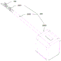
FIG. 1 is a schematic structural view of an opening and closing instrument according to an embodiment of the invention;
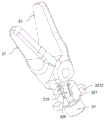
FIG. 2 is a schematic view of the instrument tip assembly and bend control assembly in accordance with an embodiment of the present invention;
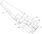
FIG. 3 is a schematic illustration of the instrument tip assembly and drive assembly shown disassembled in accordance with an embodiment of the present invention;
FIG. 4 is a schematic view of the connection of the instrument tip assembly and the drive assembly in an embodiment of the present invention;
fig. 5a and 5b are schematic structural diagrams of the first clamping portion and the second clamping portion in a first state and a second state, respectively;
FIG. 6 is an exploded view of the instrument tip assembly in a first embodiment in accordance with an embodiment of the present invention;
FIG. 7 is a schematic view of the instrument tip assembly of an embodiment of the present invention shown expanded to a maximum angle in a first embodiment;
FIG. 8 is a schematic view of an instrument tip assembly in a first embodiment of the present invention shown closed;
FIG. 9 is a schematic cross-sectional view of the instrument tip assembly of the first embodiment in accordance with an embodiment of the present invention;
fig. 10 is another schematic cross-sectional view of an instrument tip assembly in a first embodiment in accordance with an embodiment of the present invention;
FIG. 11 is a schematic view of an instrument tip assembly in a second embodiment in accordance with an embodiment of the present invention;
fig. 12 is a schematic view of an instrument tip assembly in a third embodiment in accordance with an embodiment of the present invention;
fig. 13 is a schematic view of the instrument tip assembly in a fourth embodiment in accordance with an embodiment of the present invention;
fig. 14 is an exploded view of an instrument tip assembly in a fourth embodiment in accordance with an embodiment of the present invention;
fig. 15 is a schematic view of a fourth embodiment of the open-close mechanism of the instrument tip assembly in a disassembled state according to the embodiment of the present invention;
FIG. 16 is a schematic view of a disassembled structure of the instrument tip assembly in a fourth embodiment of the opening and closing mechanism of the present invention;
fig. 17 is a schematic cross-sectional view of an instrument tip assembly in a fourth embodiment in accordance with an embodiment of the present invention;
FIG. 18 is another cross-sectional view of the instrument tip assembly of the present invention in a fourth embodiment;
FIG. 19 is an exploded view of the instrument tip assembly in a fourth embodiment of the present invention showing the drive shaft in an alternate configuration;
FIG. 20 is an exploded view of the instrument tip assembly of the present invention in a fourth embodiment with the drive portion in an alternate configuration;
FIG. 21 is an exploded view of the instrument tip assembly of the present invention in a fourth embodiment with the drive portion in an alternate configuration;
FIG. 22 is a schematic view of the opening mechanism of FIG. 21 shown open at a maximum angle;
FIG. 23 is a schematic structural view of an instrument tip assembly in a fifth embodiment in accordance with an embodiment of the present invention;
fig. 24 is an exploded view of an instrument tip assembly in a fifth embodiment in accordance with an embodiment of the present invention;
fig. 25 is a schematic view of the instrument tip assembly in a fifth embodiment of the present invention showing the open-close mechanism in a closed position, in accordance with the present invention;
fig. 26 is a schematic view of a fifth embodiment of the open-close mechanism of the instrument tip assembly in an open configuration in accordance with the present invention;
FIG. 27 is a partial schematic view of an instrument tip assembly in accordance with an embodiment of the invention with the opening and closing mechanism in an open position in a fifth embodiment;
FIG. 28 is a schematic cross-sectional view of the instrument tip assembly of the fifth embodiment in accordance with the present invention;
fig. 29 is another cross-sectional view of the instrument tip assembly of the fifth embodiment in accordance with the present invention.
Detailed Description
The details of the present invention will become more apparent in light of the accompanying drawings and description of specific embodiments thereof. However, the specific embodiments of the present invention described herein are for the purpose of illustration only and should not be construed as limiting the invention in any way. Any possible variations based on the present invention may be conceived by the skilled person in the light of the teachings of the present invention, and these should be considered to fall within the scope of the present invention. It will be understood that when an element is referred to as being "disposed on" another element, it can be directly on the other element or intervening elements may also be present. When an element is referred to as being "connected" to another element, it can be directly connected to the other element or intervening elements may also be present. The terms "mounted," "connected," and "connected" are to be construed broadly and may include, for example, mechanical or electrical connections, communications between two elements, direct connections, indirect connections through intermediaries, and the like. The terms "vertical," "horizontal," "upper," "lower," "left," "right," and the like as used herein are for illustrative purposes only and do not denote a unique embodiment.
Unless defined otherwise, all technical and scientific terms used herein have the same meaning as commonly understood by one of ordinary skill in the art to which this application belongs. The terminology used herein in the description of the present application is for the purpose of describing particular embodiments only and is not intended to be limiting of the application. As used herein, the term "and/or" includes any and all combinations of one or more of the associated listed items.
In order to solve the problem that the distal end assembly of the instrument is inconvenient to detach from the transmission assembly at the rear end and ensure that the distal end assembly of the instrument can be opened and closed, the application provides an opening and closing instrument, which can comprise: an instrument tip assembly 100 comprising: a base 1; the opening and closing mechanism 2 and the driving mechanism 3 are arranged on the base 1; the opening and closing mechanism 2 is in transmission connection with the driving mechanism 3, the base 1 can be detachably mounted on the transmission assembly 200, and the driving mechanism 3 is used for being matched with the rotating shaft 2004 on the transmission assembly 200, so that the rotating shaft 2004 drives the driving mechanism 3 to open and close the opening and closing mechanism 2 under the rotation of the rotating shaft 2004 in the axial direction of the transmission assembly 200.
The instrument end assembly 100 of the opening and closing instrument can be detached from the transmission assembly 200, so that only the instrument end assembly 100 in the opening and closing instrument can be replaced or subjected to functional treatment, such as disinfection treatment, cleaning treatment and the like, and the whole opening and closing instrument does not need to be replaced or subjected to functional treatment, which is beneficial to reducing the operation cost. Meanwhile, by using the rotating shaft 2004 in the transmission assembly 200, when the instrument distal end assembly 100 and the transmission assembly 200 are assembled together, the rotating shaft 2004 at one end of the transmission assembly 200 can be matched with the driving mechanism 3, and by driving the rotation of the rotating shaft 2004, the rotating shaft 2004 can drive the driving mechanism 3 to open and close the opening and closing mechanism 2, and the rotating shaft 2004 in the transmission assembly 200 can be separated from the driving mechanism 3, so that the detachment of the instrument distal end assembly 100 from the transmission assembly 200 cannot be influenced.
As shown in fig. 1, the opening and closing instrument may include an instrument tip assembly 100. Further, the opening and closing instrument may further include a transmission assembly 200. Transmission assembly 200 may be any type of device that transmits power to instrument tip assembly 100 by way of a mechanical transmission. Instrument tip assembly 100 is a type of device that receives mechanical power from drive assembly 200 and uses the power to effect the opening and closing operation. For example, the transmission assembly 200 may include an instrument bar 2002 for performing an lengthening function, may include a bend control assembly 2001 for performing a turning function, and may include an instrument box 2003, the instrument bar 2002 being mounted on the instrument box 2003, the instrument box 2003 in turn being mounted directly or indirectly at a robotic arm of the surgical robot, and the instrument box 2003 may provide mechanical power.
As shown in FIG. 2, to enable the opening and closing instrument to make a turn, the end of the instrument shaft 2002 is first provided with a bend control assembly 2001, and then the instrument tip assembly 100 is connected to the end of the bend control assembly 2001. As shown in fig. 3, the instrument tip assembly 100 is removably coupled to the drive assembly 200. Therefore, the instrument tip assembly 100 of the open/close instrument can be detached from the transmission assembly 200, so that only the instrument tip assembly 100 of the open/close instrument can be replaced or functionally treated, such as a disinfection treatment, a cleaning treatment, etc., without replacing or functionally treating the entire open/close instrument, which is beneficial to reducing the cost of the operation.
Specifically, the instrument tip assembly 100 may include: a base 1; an opening and closing mechanism 2 and a driving mechanism 3 which are arranged on the base 1. In the present application, the base 1 can be removably mounted to the drive assembly 200 to enable removable connection between the instrument tip assembly 100 and the drive assembly 200. When the base 1 and the transmission assembly 200 are assembled together, the driving mechanism 3 is engaged with the rotating shaft 2004 of the transmission assembly 200. The opening and closing mechanism 2 is in transmission connection with the driving mechanism 3. As shown in fig. 4, one end of the transmission assembly 200 has a rotating shaft 2004 capable of cooperating with the driving mechanism 3, and when the base 1 and the transmission assembly 200 are mounted and fitted together, the rotating shaft 2004 can rotate around the axial direction of the transmission assembly 200 to drive the driving mechanism 3 so as to enable the opening and closing mechanism 2 to open and close.
As shown in fig. 3 and 4, one end of the transmission assembly 200 has a second clamping portion 2005, one end of the base 1 facing the transmission assembly 200 (i.e., the end facing away from the opening and closing mechanism 2) has a first clamping portion 11, and the first clamping portion 11 can slide into the second clamping portion 2005 along the radial direction of the second clamping portion 2005, so as to realize the detachable connection between the base 1 and the transmission assembly 200. The second clamping portion 2005 can be located at an end of the instrument rod 2002, and can also be located at an end of the bending control assembly 2001, which is not limited in any way in this application. The shaft 2004 may be inserted into the transmission assembly 200, and may be a flexible shaft 2004 or a rigid shaft 2004. After the first engaging portion 11 slides into the second engaging portion 2005, the rotating shaft 2004 can cooperate with the driving mechanism 3 to realize transmission therebetween.
Further, first joint portion 11 can be spacing shape to make first joint portion 11 unable rotate after sliding into second joint portion 2005, thereby ensure the angle of mechanism 2 that opens and shuts. The limiting shape is as follows: the racetrack shape, including the parallel structure of the two opposite sides of the first clamping portion 11, can also ensure that the first clamping portion 11 can slide into the second clamping portion 2005 from two directions, which is more convenient for the installation of the instrument tip assembly on the transmission assembly 200.
In another embodiment, fig. 5a and 5b are schematic structural diagrams of the first clamping portion and the second clamping portion in the first state and the second state, respectively, as shown in fig. 5a and 5b, the first clamping portion 11 can slide into the second clamping portion 2005 from the radial direction of the transmission assembly 200, after the first clamping portion 11 slides into the second clamping portion 2005, the first clamping portion 11 can rotate relative to the second clamping portion 2005 by a preset angle, so that the first clamping portion 11 and the second clamping portion 2005 have the first state and the second state therebetween, and in the first state, the first clamping portion 11 can slide out of the second clamping portion 2005 along the radial direction of the transmission assembly 200; in the second state, the first catching portion 11 is held in the second catching portion 2005 and cannot slide out of the second catching portion 2005 in the radial direction of the transmission assembly 200. Specifically, after the first engaging portion 11 completely slides into the second engaging portion 2005, the second engaging portion 2005 has a limiting notch 20051 for the first engaging portion 11 to rotate by a predetermined angle, and at least a portion of the first engaging portion 11 can not rotate continuously after rotating into the limiting notch 20051, and can not slide out of the second engaging portion 2005 along the radial direction of the transmission assembly 200.
Further, a resistance increasing structure may be provided between the first catching portion 11 and the second catching portion 2005. The resistance increasing structure may include a protrusion structure provided on the first click portion 11 and a recess structure provided on the second click portion 2005 corresponding to the protrusion structure. Alternatively, the resistance increasing structure may include a concave structure provided on the first click portion 11 and a convex structure corresponding to the concave structure provided on the second click portion 2005. Under the second state, protruding structure gets into the concave structure to hinder first joint portion 11 and second joint portion 2005 from the second state to resume to the first state to a certain extent, need make between first joint portion 11 and the second joint portion 2005 resume to the first state from the second state through the rotation that uses more strength.
In order to realize that the rotating shaft 2004 rotates around the axial direction of the transmission assembly 200 to drive the driving mechanism 3, so that the opening and closing mechanism 2 can realize opening and closing, as shown in fig. 4, the opening and closing mechanism 2 may include: two clamps 21 provided on the base 1 via a shaft body 22.
The two clamping members 21 may be clamping structures in scissors, arc shears, electrocoagulation forceps, monopolar arc shears, grasping forceps, needle holding forceps, and the like. The base 1 is provided with a through hole 12 along the axis direction thereof. The driving mechanism 3 may include a driving shaft 31 inserted into the through hole 12, and a transmission mechanism 32 in transmission connection with the driving shaft 31. After the first clamping portion 11 slides into the second clamping portion 2005, the driving shaft 31 is used for being matched with the rotating shaft 2004 for transmission. The rotating shaft 2004 can drive the driving shaft 31 to rotate around the axis direction of the transmission assembly 200 so that the driving shaft 31 drives the transmission mechanism 32 to move, and further the transmission mechanism 32 drives the opening and closing mechanism 2 to open and close.
As shown in fig. 6 and 9, the driving shaft 31 has a stepped structure on the side wall thereof, and the inner side wall of the through-hole 12 of the base 1 also has a stepped structure corresponding to the stepped structure of the driving shaft 31, whereby the driving shaft 31 is prevented from being separated from the through-hole 12 from the side of the holder 21. The drive shaft 31 may have a catch 311 on a side wall thereof. The driving mechanism 3 further includes a retaining ring 312 disposed in the locking groove 311, the retaining ring 312 is located on a side of the base 1 facing the clamping member 21, and the retaining ring 312 can abut against the base 1 to retain the driving shaft 31 in the through hole 12, so as to prevent the driving shaft 31 from being separated from the through hole 12 from the side of the transmission assembly 200.
For example, the end of the driving shaft 31 facing the transmission assembly 200 is opened with a transmission hole 313. The shaft 2004 can extend and retract along the axis of the transmission assembly 200. After the first engaging portion 11 slides into the second engaging portion 2005, the shaft 2004 can extend out to enter the transmission hole 313, for example, the protruding shape of the end of the shaft 2004 can be inserted into the transmission hole 313, so as to form a snap-fit, and the shaft 2004 can drive the driving shaft 31 to rotate. The shaft 2004 of the transmission assembly 200 is extendable and retractable in the axial direction of the transmission assembly 200. When the first engaging portion 11 is completely slid into the second engaging portion 2005 of the transmission assembly 200, the shaft 2004 can be extended in the axial direction of the transmission assembly 200 such that the shaft 2004 enters the transmission hole 313 of the driving shaft 31, thereby retaining the instrument tip assembly 100 on the transmission assembly 200. Based on the structure, the instrument tail end assembly 100 can be effectively prevented from automatically sliding out and falling off from the second clamping part 2005 of the transmission assembly 200 through the guide part. As a possibility, the end of the rotation shaft 2004 may have a guide portion, and the protruding shape of the end of the rotation shaft 2004 may be the guide portion. When the first engaging portion 11 slides into the second engaging portion 2005 of the transmission assembly 200, the base 1 presses the guiding portion downward so that the rotating shaft 2004 contracts in the axial direction of the transmission assembly 200 and the first engaging portion 11 can continuously slide into the second engaging portion 2005 of the transmission assembly 200; when the instrument tip assembly 100 needs to be detached from the second clamping portion 2005 of the transmission assembly 200, the first clamping portion 11 of the instrument tip assembly 100 only needs to be slid out of the second clamping portion 2005 of the transmission assembly 200 with a large force, and in the process, the base 1 presses the guide portion again to contract the rotating shaft 2004 in the axial direction of the transmission assembly 200, so that the first clamping portion 11 can slide out of the second clamping portion 2005 of the transmission assembly 200. In other possible embodiments, before the first engaging portion 11 slides into the second engaging portion 2005 of the transmission assembly 200, the rotating shaft 2004 may be contracted in the axial direction of the transmission assembly 200 by operating the button, so that the first engaging portion 11 can slide into the second engaging portion 2005 of the transmission assembly 200 smoothly; after the first engaging portion 11 slides into the second engaging portion 2005 of the transmission assembly 200, the shaft 2004 may be extended in the axial direction of the transmission assembly 200 by operating the button to enter the guide portion into the transmission hole 313 of the driving shaft 31, so that the instrument tip assembly 100 is held on the transmission assembly 200.
One end of the base 1, which faces away from the transmission assembly 200, is provided with two oppositely arranged supporting portions 13, the supporting portions 13 extend along the axial direction of the base 1, and a spacing distance is arranged between the two supporting portions 13 for accommodating the clamping piece 21 and the transmission mechanism 32. Two holders 21 pass through the axis body 22 and set up on the supporting part 13 of base 1, wear to establish two holders 21, second supporting part 13 again in proper order through first supporting part 13 if the axis body 22 in proper order, and for example, the axis body 22 can be two again, and first axis body 22 wears to establish first supporting part 13 in proper order, first holder 21 and second supporting part 13, and second axis body 22 wears to establish first supporting part 13 in proper order, second holder 21 and second supporting part 13.
The transmission mechanism 32 can have various forms to drive the opening and closing mechanism 2 to open and close. For example, the transmission between the rotating shaft 2004 and the opening and closing mechanism 2 can be realized by a thread structure, and can also be realized by a groove structure which is matched with the clamping piece 21 to rotate around the axis of the transmission mechanism 32.
In the first embodiment, the transmission between the rotating shaft 2004 and the opening and closing mechanism 2 can be realized by a thread structure, as shown in fig. 6 to 10, two clamping members 21 are hinged together by a shaft body 22, two ends of the shaft body 22 are respectively arranged on the two supporting portions 13 in a penetrating way, and the clamping members 21 can rotate around the shaft body 22, so as to achieve the opening and closing.
As shown in fig. 6 to 10, at least one of the clamping members 21 has a guide groove 211 formed therein. The extending direction of the guide groove 211 has a predetermined angle with the axial direction of the drive shaft 31. The guide groove 211 is formed at a side of the rotation shaft 2004 adjacent to the transmission assembly 200. The base 1 has a limiting groove 131. Further, the stopper groove 131 extends in the axial direction of the drive shaft 31. The position-limiting groove 131 may be disposed on the supporting portion 13 of the base 1, and the position-limiting groove 131 is located on a side of the rotating shaft 2004 close to the transmission assembly 200. The transmission mechanism 32 may include a transmission member 321, and the transmission member 321 has a threaded hole and a guide post 3211 extending in a radial direction. At least a part of the outer side wall of the drive shaft 31 has an external thread, and the drive shaft 31 is screwed in the threaded hole through the external thread. The transmission member 321 can be moved back and forth in the axial direction of the drive shaft 31 by the rotation of the drive shaft 31.
As shown in fig. 6 to 10, the guide post 3211 extends into the limiting groove 131 and the guide groove 211, when the driving member 321 moves along the axial direction of the driving shaft 31 by the driving shaft 31, the guide post 3211 is limited by the limiting groove 131, and can only move back and forth along the axial direction of the driving shaft 31, but cannot move along the radial direction of the driving shaft 31, at this time, because the extending direction of the guide groove 211 and the axial direction of the driving shaft 31 have a predetermined included angle, when the guide post 3211 moves back and forth along the axial direction of the driving shaft 31, the guide post 3211 can push the clamping member 21 with the guide groove 211 to deflect around the shaft body 22, and the degree of deflection is determined by the size of the predetermined included angle and the detail of the back and forth movement of the guide post 3211 along the axial direction of the driving shaft 31.
When the guide post 3211 controls one of the clamping members 21 to rotate, the other clamping member 21 only needs to be fixed with the base 1, and the two clamping members 21 can be opened and closed.
Further, the two supporting portions 13 respectively have a limiting groove 131. The transmission member 321 has a guide post 3211 on each of two opposite sides. The two holding members 21 have guide grooves 211, respectively. The two guide posts 3211 penetrate through the corresponding retaining grooves 131 and guide grooves 211. In this way, the transmission member 321 can control the two clamping members 21 to rotate simultaneously through the guide posts 3211, so as to open and close. Of course, the extending directions of the guide grooves 211 on the clamp 21 need to be symmetrically arranged. In addition, the top end of the driving shaft 31 may pass through the shaft body 22, thereby preventing the shaft body 22 from slipping out.
In the above embodiment, the transmission mechanism 32 only needs one transmission member 321 to drive the opening and closing mechanism 2 to open and close, so that the instrument distal end assembly 100 has the advantages of simple structure and high transmission efficiency.
In the second embodiment, the transmission between the rotating shaft 2004 and the opening and closing mechanism 2 can be realized by a thread structure, as shown in fig. 11, the transmission mechanism 32 can be: a transmission member 321 threadedly coupled to the driving shaft 31, wherein the driving shaft 31 can drive the transmission member 321 to move along the axial direction of the driving shaft 31; a first linkage link 322; a second linkage link 323. The transmission member 321 may penetrate through the driving shaft 31, or may be sleeved outside the driving shaft 31. One clamping member 21 has a first linkage part 212, the other clamping member 21 has a second linkage part 213, one end of the first linkage link 322 and one end of the second linkage link 323 are hinged to the transmission member 321, the other end of the first linkage link 322 is hinged to the first linkage part 212, and the other end of the second linkage link 323 is hinged to the second linkage part 213. When the driving shaft 31 rotates, the transmission member 321 is restricted by the first linkage link 322 and the second linkage link 323 and cannot rotate together, so that the transmission member 321 moves in the axial direction of the driving shaft 31, and the included angle between the first linkage link 322 and the second linkage link 323 increases or decreases, and further the included angle between the first linkage part 212 and the second linkage part 213 increases or decreases, that is, the opening and closing of the two clamping members 21 are realized. As a practical matter, the length of the hinge where one end of the first linkage link 322 is hinged to the transmission member 321 from the hinge where the other end of the first linkage link 322 is hinged to the first linkage portion 212 is equal to the length of the hinge where one end of the second linkage link 323 is hinged to the transmission member 321 from the hinge where the other end of the second linkage link 323 is hinged to the second linkage portion 213. Similarly, the distance between the hinge of one end of the second linkage 323 and the transmission member 321 and the hinge of the two clamping members 21 is equal to the distance between the hinge of the other end of the second linkage 323 and the second linkage 213 and the hinge of the two clamping members 21.
In the third embodiment, the transmission between the rotating shaft 2004 and the opening and closing mechanism 2 can be realized by a thread structure as shown in fig. 12, and the transmission mechanism 32 can include: a transmission member 321. The driving shaft 31 is fixedly connected to the transmission member 321, for example, the transmission member 321 is fixedly sleeved outside the driving shaft 31. The transmission member 321 has an external thread. In this embodiment, there are two shaft bodies 22. The first holding part 21 is articulated to the base 1 via a first axle 22, and the second holding part 21 is articulated to the base 1 via a second axle 22. The two shafts 22 are spaced apart from each other to accommodate the transmission member 321. The first holding member 21 has a rotating tooth 214 engaged with the external thread of the transmission member 321 at a position rotated around the first shaft body 22, the second holding member 21 has a rotating tooth 214 engaged with the external thread of the transmission member 321 at a position rotated around the second shaft body 22, and the rotating tooth 214 of the first holding member 21 and the rotating tooth 214 of the second holding member 21 are respectively located on both sides of the transmission member 321. When the driving shaft 31 drives the transmission member 321 to rotate, the rotating teeth 214 rotate around the shaft 22, thereby driving the clamping member 21 to rotate. Depending on the direction of rotation of the drive shaft 31, the opening or closing between the two clamps 21 can be controlled.
In the fourth embodiment, the transmission between the rotating shaft 2004 and the opening and closing mechanism 2 is realized by the way that the groove structure is matched with the clamping piece 21 to rotate around the axis of the transmission mechanism 32. As shown in fig. 13 to 19, the transmission mechanism 32 may include: the transmission member 321. The driving shaft 31 can drive the transmission member 321 to rotate around the axis of the transmission assembly 200. The end surface of the transmission member 321 facing the driving shaft 31 can be matched with the end surface of the driving shaft 31 facing the transmission member 321 through a matching structure to realize transmission connection. For example, as shown in fig. 14 and 17, the fitting structure may include: a connecting hole formed in the driving member 321, and a rod body portion formed in the driving shaft 31 and inserted into the connecting hole. The connecting hole and the rod body part can be one or more. When the number of the connecting holes and the lever body is two or more, the transmission between the driving shaft 31 and the transmission member 321 is more smooth and flexible. The connecting hole and the rod body portion may be one, and the cross section of the connecting hole and the rod body portion may be non-circular, or the connecting hole and the rod body portion may not be located at the rotation center of the driving shaft 31 and the driving member 321.
As shown in fig. 19, the fitting structure may further include: a recess or a boss formed on the transmission member 321; projections or recesses are formed on the drive shaft 31 corresponding to the recesses or projections formed on the transmission member 321. The specific shapes of the groove and the boss are not limited in the application, and only the requirement of realizing transmission is met, and the groove and the boss can be in a straight line shape, a triangle shape, a quadrangle shape, a cross shape and the like.
As shown in fig. 14 to 16 and 18, the end surface of the transmission member 321 facing the clamping member 21 may be formed with two first transmission grooves 3214, and the two first transmission grooves 3214 are symmetrically disposed with respect to the axis of the transmission member 321. The first transmission groove 3214 may extend in a radial direction of the transmission member 321. The ends of the two holding elements 21 facing the transmission element 321 each have a transmission part 215 arranged in the two first transmission recesses 3214. The driving shaft 31 can rotate the transmission member 321 around the axial direction of the transmission assembly 200. When the transmission member 321 rotates, the transmission member 321 passes through the first transmission groove 3214, so that the transmission portion 215 of the clamping member 21 rotates around the shaft 22, and the two clamping members 21 rotate in opposite directions, thereby enabling the two clamping members 21 to open and close. As shown in fig. 15, at the angle of the transmission member 321, the two clamping members 21 are in a closed state. At this point in the angle of the transmission member 321, the two clamping members 21 are in an open position, as shown in fig. 16. The groove structure includes a first drive groove 3214. Under the structure, the driving shaft 31 can realize the opening and closing of the opening and closing mechanism only by a small amount of rotation angles, so that the opening and closing mechanism can be controlled to open and close more quickly and efficiently.
When the two clamping members 21 are in the closed state, the distance from the center of the transmission part 215 to the axis of the transmission member 321 is m/2; when the two clamping pieces 21 are in the opening state, the distance from the center of the transmission part 215 to the axis of the transmission piece 321 is n/2; wherein n/2 is greater than m/2.
Further, as shown in fig. 15 and 16, the transmission portion 215 may be at least partially spherical. The diameter of the transmission portion 215 is d, and the width of the first transmission groove 3214 is s, wherein s is greater than or equal to d. When the transmission member 321 drives the transmission portion 215 of the clamping member 21 to rotate around the shaft 22 through the first transmission groove 3214, the first transmission groove 3214 of the transmission member 321 contacts with the spherical portion of the transmission portion 215, the inner side surface of the first transmission groove 3214 pushes the clamping member 21 to rotate around the shaft 22, and the spherical center of the spherical portion of the transmission portion 215 is away from the axis of the driving shaft 31. The at least partially spherical transmission part 215 can prevent the non-spherical part of the transmission part 215 from being clamped with the side wall of the first transmission groove 3214 in the rotation process of the clamping member 21, so that the whole rotation process is more flexible, and the clamping member 21 can be ensured to have a larger rotation angle.
As shown in fig. 20, the transmission mechanism 32 may further include, as applicable: the spherical rollers 324 are respectively sleeved on the transmission part 215, and the rollers 324 can rotate around the axis of the transmission part 215. Since the roller 324 can rotate around the axis of the transmission part 215, when the roller 324 contacts the inner sidewall of the first transmission groove 3214, the original sliding friction can be converted into rolling friction, thereby further reducing the friction resistance, and improving the transmission efficiency and the flexibility during rotation.
As shown in fig. 15 and 16, as a practical matter, the transmission member 321 has a limit boss 3212 extending in the radial direction thereof on the outer side wall thereof, and the base 1 has a limit portion 14 thereon; when the two clamping members 21 are opened to the maximum angle or the minimum angle, the limit boss 3212 abuts against the limit portion 14. In this way, the range of the rotation angle of the holder 21 is controlled by the stopper portion 14. In addition, the limiting portion 14 is used to prevent the clamping member 21 from rotating too much, once the clamping member 21 rotates too much, the transmission portion 215 of the clamping member 21 may be disengaged from the first transmission groove 3214, and after the transmission portion 215 of the clamping member 21 is disengaged from the first transmission groove 3214, the transmission connection between the clamping member 21 and the clamping member 21 is lost, and the transmission member 321 loses transmission control over the clamping member 21. The position-limiting part 14 may be a new structure formed on the base 1, for example, a step formed at the periphery of the end surface of the base 1 and capable of abutting against the position-limiting boss 3212, and the position-limiting part 14 can abut against the position-limiting boss 3212 when the two clamping members 21 are in the open state and reach the maximum open angle. The limiting portion 14 may be a supporting portion 13 originally provided on the base 1, and a side wall of the supporting portion 13 may abut against the limiting boss 3212 when the two clamping members 21 are in the closed state.
As a practical matter, the base 1 may have a blocking portion 15 thereon, as shown in fig. 21 and 22. The stopper 15 is located outside the transmission member 321 in the circumferential direction, and for example, the stopper 15 may be provided on the support portion 13. When the two clamping members 21 are opened to the maximum angle, the blocking portion 15 abuts against the transmission portion 215 or the roller 324, so as to prevent the clamping members 21 from being opened to a larger angle, and the transmission portion 215 or the roller 324 of the clamping member 21 is disengaged from the first transmission groove 3214 of the transmission member 321, so that the transmission member 321 loses transmission control over the clamping members 21. On the other hand, the transmission portion 215 or the roller 324 may be partially separated from the first transmission groove 3214, but is blocked by the blocking portion 15 to ensure that the transmission portion is not completely separated from the first transmission groove 3214, so that the maximum angle θ that the clamping member 21 can be opened can be increased to some extent by the above-mentioned structure.
In many of the embodiments described above, instrument tip assembly 100 is the most compact, has a low number of parts, and is space efficient. In particular, the dimension of the transmission member 321 in the axial direction thereof can be small, and therefore, the dimension of the base 1 in the axial direction of the transmission member 321 can be made smaller, thereby facilitating finer control of the instrument tip assembly 100 and having higher transmission efficiency.
In the fifth embodiment, the transmission between the rotating shaft 2004 and the opening and closing mechanism 2 is realized by the way that the groove structure is matched with the clamping piece 21 to rotate around the axis of the transmission mechanism 32. As shown in fig. 23 to 29, the transmission mechanism 32 may include: transmission member 321, rotation post 325. The driving shaft 31 is in transmission connection with the transmission member 321, and the transmission member 321 can rotate by the rotation of the driving shaft 31. The transmission connection between the drive shaft 31 and the transmission member 321 may be similar to that described above and will not be described in detail here.
As shown in fig. 23 to 28, the transmission member 321 has two rotation grooves 3213 extending along a radial direction of the transmission member 321 on an end surface facing the clamping member 21, and the two rotation grooves 3213 are symmetrically arranged with respect to an axis of the transmission member 321. The number of the rotating posts 325 may be two, and the two rotating posts 325 are respectively disposed in the two rotating grooves 3213. The side of the two rotation posts 325 facing the clamp 21 needs to leak out of the rotation grooves 3213. The rotating post 325 is capable of rotating about the axis of the rotating post 325 in the rotating slot 3213. The two rotation posts 325 respectively have a second transmission groove 3251, the second transmission groove 3251 may be located on a sidewall of the rotation post 325, and the second transmission groove 3251 may extend along an axial direction of the rotation post 325. The ends of the two holding parts 21 facing the transmission part 321 each have a transmission part 215 arranged in two second transmission grooves 3251. Similarly, in the above structure, the driving shaft 31 can be opened and closed by a small amount of rotation angle, so that the opening and closing of the opening and closing mechanism can be controlled more quickly and efficiently. Through the existence of rotating post 325, it can rotate around the axis of self to the offset of compensation holder 21 under the in-process transmission portion 215 rotation of opening and shutting, consequently, transmission portion can be cylindricly still can guarantee that driving medium 321 drives the smooth degree that the mechanism opened and shut through rotating, can not take place the jamming, and the mechanism that opens and shuts contained angle also can further increase when opening the state.
As shown in fig. 25 and 26, when the two holding members 21 are in the closed state, the distance from the center of the transmission part 215 to the axis of the transmission member 321 is m/2; when the two clamping pieces 21 are in the opening state, the distance from the center of the transmission part 215 to the axis of the transmission piece 321 is n/2; wherein n/2 is greater than m/2.
When the driving shaft 31 drives the transmission member 321 to rotate around the axis of the transmission member 321, the transmission member 321 rotates, and at the same time, the rotation column 325 also rotates around the axis of the transmission member 321. The transmission part 215 disposed in the second transmission groove 3251 of the rotation column 325 rotates around the shaft 22, and in the process, the rotation column 325 deflects around its axis, so that the orientation of the second transmission groove 3251 changes to meet the requirement that the transmission part 215 rotates around the shaft 22. For example, as shown in fig. 24, 27 and 28, when the two clamping members 21 are in the closed state, the axis of the transmission portion 215 on the clamping member 21 and the axis of the transmission member 321 are in a parallel state. As shown in fig. 25 and fig. 26, after the transmission member 321 rotates clockwise, the two clamping members 21 are in an open state, the axes of the transmission portions 215 on the two clamping members 21 respectively form an angle with the axis of the transmission member 321, the rotation directions of the transmission portions 215 on the two clamping members 21 around the shaft body 22 are opposite, and the directions of the two rotation columns 325 respectively deflecting around their axes are opposite.
As shown in fig. 24 and 25, similar to the structure of the fourth embodiment, the outer side wall of the transmission member 321 has a limit boss 3212 extending along the radial direction thereof, and the base 1 has a limit portion 14; when the two clamping members 21 are opened to the maximum angle or the minimum angle, the limit boss 3212 abuts against the limit portion 14.
In many of the embodiments described above, instrument tip assembly 100 is compact and space efficient. In particular, the dimension of the transmission member 321 in the axial direction thereof can be small, and therefore, the dimension of the base 1 in the axial direction of the transmission member 321 can be made smaller, thereby facilitating finer control of the instrument tip assembly 100 and having higher transmission efficiency. In addition, since the transmission portion 215 of the clamping member 21 is inserted into the second transmission groove 3251 of the rotation column 325, and the rotation column 325 rotates around its axis to satisfy the rotation of the transmission portion 215 of the clamping member 21, the diameter of the transmission portion 215 of the clamping member 21 can be substantially the same as the width S of the second transmission groove 3251 of the rotation column 325, and the gap between the two can be small, so that the transmission portion 215 is not easily separated from the second transmission groove 3251 during the rotation process of the transmission portion 215 around the shaft 22.
The embodiments in the present specification are described in a progressive manner, each embodiment focuses on differences from other embodiments, and the same and similar parts among the embodiments are referred to each other. The above embodiments are only for illustrating the technical idea and features of the present invention, and the purpose of the present invention is to enable those skilled in the art to understand the content of the present invention and implement the present invention, and not to limit the protection scope of the present invention by this means. All equivalent changes and modifications made according to the spirit of the present invention should be covered in the protection scope of the present invention.
Claims (15)
1. An opening and closing instrument, comprising:
an instrument tip assembly comprising: a base; the opening and closing mechanism and the driving mechanism are arranged on the base;
the opening and closing mechanism is in transmission connection with the driving mechanism, the base can be detachably mounted on the transmission assembly, and the driving mechanism is used for being matched with a rotating shaft on the transmission assembly, so that the rotating shaft drives the driving mechanism to rotate around the axis direction of the transmission assembly, and the opening and closing of the opening and closing mechanism are achieved.
2. The opening and closing instrument as claimed in claim 1, wherein one end of the base facing away from the opening and closing mechanism is provided with a first clamping portion, one end of the transmission assembly is provided with a second clamping portion, and the base can slide into the second clamping portion along the radial direction of the second clamping portion through the first clamping portion, so that the base can be detachably mounted at the end portion of the transmission assembly.
3. The opening-closing appliance according to claim 2, wherein the base is provided with a through hole along the axial direction of the base; the driving mechanism comprises a driving shaft penetrating through the through hole, and the driving shaft is used for being matched with the rotating shaft for transmission;
the rotating shaft on the transmission assembly can extend and retract in the axial direction of the transmission assembly; when the first clamping portion completely slides into the second clamping portion of the transmission assembly, the rotating shaft can extend out in the axis direction of the transmission assembly so as to enable the rotating shaft to enter the transmission hole of the driving shaft.
4. The opening and closing instrument as claimed in claim 1, wherein the base is provided with a through hole along its axis; the driving mechanism comprises a driving shaft penetrating through the through hole and a transmission mechanism in transmission connection with the driving shaft, and the driving shaft is used for being matched with the rotating shaft for transmission; the rotating shaft can drive the driving shaft to rotate around the axis direction of the transmission assembly so that the driving shaft drives the transmission mechanism to move, and then the transmission mechanism drives the opening and closing mechanism to open and close.
5. The opening and closing instrument of claim 4, wherein the opening and closing mechanism comprises: two clamping pieces arranged on the base through a shaft body, wherein at least one clamping piece is provided with a guide groove; the base is provided with a limiting groove; the transmission mechanism comprises a transmission piece, a threaded hole and a guide post extending along the radial direction are formed in the transmission piece, external threads are formed on at least part of the outer side wall of the driving shaft, the driving shaft is screwed in the threaded hole through the external threads, the guide post extends into the limiting groove and the guide groove, and when the driving shaft drives the transmission piece to move along the axis direction of the driving shaft, the guide post drives the clamping piece to be opened and closed.
6. The opening and closing instrument according to claim 4, wherein the side wall of the driving shaft is provided with a clamping groove; the driving mechanism further comprises a retainer ring arranged in the clamping groove, and the retainer ring can abut against the base to keep the driving shaft in the through hole.
7. The opening and closing instrument of claim 4, wherein the transmission mechanism comprises: the transmission piece is in threaded connection with the driving shaft, and the driving shaft can drive the transmission piece to move along the axial direction of the driving shaft; a first linkage link; a second linkage link;
the mechanism that opens and shuts includes: the clamping piece is arranged on the base through a shaft body, one clamping piece is provided with a first linkage part, the other clamping piece is provided with a second linkage part, one end of the first linkage connecting rod and one end of the second linkage connecting rod are hinged with the transmission piece, the other end of the first linkage connecting rod is hinged with the first linkage part, and the other end of the second linkage connecting rod is hinged with the second linkage part.
8. The opening and closing instrument of claim 4, wherein the opening and closing mechanism comprises: two clamping pieces arranged on the base through a shaft body; the transmission mechanism includes: the driving shaft is fixedly connected with the transmission piece; the transmission piece is provided with an external thread, the first clamping piece is hinged to the base through a first shaft body, the second clamping piece is hinged to the base through a second shaft body, a rotating tooth meshed with the external thread of the transmission piece is arranged at the position, rotated around the first shaft body, of the first clamping piece, a rotating tooth meshed with the external thread of the transmission piece is arranged at the position, rotated around the second shaft body, of the second clamping piece, and the rotating tooth of the first clamping piece and the rotating tooth of the second clamping piece are located on two sides of the transmission piece respectively.
9. The opening and closing instrument of claim 4, wherein the opening and closing mechanism comprises: two clamping pieces arranged on the base through a shaft body; the transmission between the transmission mechanism and the opening and closing mechanism is realized in a way that the groove structure is matched with the clamping piece to rotate around the axis of the transmission mechanism.
10. The switching instrument according to claim 9, wherein the transmission mechanism comprises: the end face, facing the clamping piece, of the transmission piece is provided with two first transmission grooves, and the two first transmission grooves are symmetrically arranged relative to the axis of the transmission piece;
one ends of the two clamping pieces facing the transmission piece are respectively provided with a transmission part arranged in the two first transmission grooves;
the driving shaft can drive the transmission part to rotate around the axis direction of the transmission assembly.
11. The opening and closing instrument of claim 10, wherein the transmission portion is at least partially spherical; or,
the transmission mechanism further includes: the spherical rollers are respectively sleeved on the transmission parts and can rotate around the axes of the transmission parts.
12. The opening and closing instrument as claimed in claim 10, wherein one end of the base away from the transmission assembly has two support portions arranged oppositely, the two clamping members are hinged together by the shaft body, and two ends of the shaft body are respectively arranged on the two support portions in a penetrating manner; the outer side wall of the transmission part is provided with a limiting boss extending along the radial direction of the transmission part, and the base is provided with a limiting part; when the two clamping pieces are opened to the maximum angle or the minimum angle, the limiting boss props against the limiting part.
13. The opening and closing instrument according to claim 11, wherein the base has a blocking portion located on the circumferential outer side of the transmission member, and the blocking portion abuts against the transmission member or the roller when the two clamping members are opened to a maximum angle.
14. The opening and closing instrument of claim 9, wherein the transmission mechanism comprises:
the end face of the transmission piece facing the clamping piece is provided with two rotating grooves extending along the radial direction of the transmission piece, and the two rotating grooves are symmetrically arranged relative to the axis of the transmission piece;
the rotating columns are respectively arranged in the two rotating grooves and can rotate around the axis of the rotating column in the rotating grooves, and the two rotating columns are respectively provided with a second transmission groove;
one end of each of the two clamping pieces, which faces the transmission piece, is provided with a transmission part arranged in the two second transmission grooves.
15. The opening and closing instrument as claimed in claim 4, wherein the end of the driving shaft facing the transmission assembly is provided with a transmission hole; the rotating shaft can stretch out and draw back along the axis direction of the transmission assembly to enter the transmission hole, so that the driving shaft is driven to rotate.
Priority Applications (1)
| Application Number | Priority Date | Filing Date | Title |
|---|---|---|---|
| CN202211548756.0A CN115737113A (en) | 2022-12-05 | 2022-12-05 | Opening and closing instrument |
Applications Claiming Priority (1)
| Application Number | Priority Date | Filing Date | Title |
|---|---|---|---|
| CN202211548756.0A CN115737113A (en) | 2022-12-05 | 2022-12-05 | Opening and closing instrument |
Publications (1)
| Publication Number | Publication Date |
|---|---|
| CN115737113A true CN115737113A (en) | 2023-03-07 |
Family
ID=85343244
Family Applications (1)
| Application Number | Title | Priority Date | Filing Date |
|---|---|---|---|
| CN202211548756.0A Pending CN115737113A (en) | 2022-12-05 | 2022-12-05 | Opening and closing instrument |
Country Status (1)
| Country | Link |
|---|---|
| CN (1) | CN115737113A (en) |
Citations (6)
| Publication number | Priority date | Publication date | Assignee | Title |
|---|---|---|---|---|
| JP2011083476A (en) * | 2009-10-16 | 2011-04-28 | National Cancer Center | Medical opening/closing forceps |
| US20120215220A1 (en) * | 2011-02-18 | 2012-08-23 | Intuitive Surgical Operations, Inc. | Fusing and cutting surgical instrument and related methods |
| EP3155991A1 (en) * | 2015-10-14 | 2017-04-19 | Karl Storz GmbH & Co. KG | Distal head assembly for a bipolar instrument, bipolar instrument and method of assembling a distal head assembly |
| GB201903711D0 (en) * | 2019-03-19 | 2019-05-01 | Gyrus Medical Ltd | An end effector for a surgical instrument |
| CN113143353A (en) * | 2018-08-24 | 2021-07-23 | 上海微创医疗机器人(集团)股份有限公司 | Snake-shaped surgical instrument |
| CN114028028A (en) * | 2021-10-22 | 2022-02-11 | 上海汇禾医疗科技有限公司 | Medical instrument locked in clamping mode and using method thereof |
-
2022
- 2022-12-05 CN CN202211548756.0A patent/CN115737113A/en active Pending
Patent Citations (6)
| Publication number | Priority date | Publication date | Assignee | Title |
|---|---|---|---|---|
| JP2011083476A (en) * | 2009-10-16 | 2011-04-28 | National Cancer Center | Medical opening/closing forceps |
| US20120215220A1 (en) * | 2011-02-18 | 2012-08-23 | Intuitive Surgical Operations, Inc. | Fusing and cutting surgical instrument and related methods |
| EP3155991A1 (en) * | 2015-10-14 | 2017-04-19 | Karl Storz GmbH & Co. KG | Distal head assembly for a bipolar instrument, bipolar instrument and method of assembling a distal head assembly |
| CN113143353A (en) * | 2018-08-24 | 2021-07-23 | 上海微创医疗机器人(集团)股份有限公司 | Snake-shaped surgical instrument |
| GB201903711D0 (en) * | 2019-03-19 | 2019-05-01 | Gyrus Medical Ltd | An end effector for a surgical instrument |
| CN114028028A (en) * | 2021-10-22 | 2022-02-11 | 上海汇禾医疗科技有限公司 | Medical instrument locked in clamping mode and using method thereof |
Non-Patent Citations (1)
| Title |
|---|
| 杨德伟等: "一种力感知型手术器械驱动装置的设计与实现", 华中科技大学学报(自然科学版), no. 06, 23 June 2020 (2020-06-23), pages 82 - 87 * |
Similar Documents
| Publication | Publication Date | Title |
|---|---|---|
| US11497496B2 (en) | Surgical instrument having interlocking mechanism | |
| US10660623B2 (en) | Centering mechanism for articulation joint | |
| EP3369384B1 (en) | Adapter with centering mechanism for articulation joint | |
| EP3664726B1 (en) | Articulating tool for endoscopic placement of fasteners | |
| US9962168B2 (en) | Method and apparatus for performing minimally invasive arthroscopic procedures | |
| EP2488110B1 (en) | Surgical rod scorer and method of use of the same | |
| EP2502583A1 (en) | Surgical instrument with rotary cutting member and quick release coupling arrangement | |
| WO2011084425A1 (en) | Intralumenal accessory tip for endoscopic sheath arrangements | |
| US10702285B2 (en) | Method and apparatus for performing minimally invasive arthroscopic procedures | |
| JPH04246344A (en) | Surgical tool for endoscopy | |
| US20170055971A1 (en) | Articulating surgical devices and loaders having stabilizing features | |
| US10335129B2 (en) | Methods and devices for auto return of articulated end effectors | |
| US10307158B2 (en) | Articulating assembly and surgical instrument using the same | |
| US9492188B2 (en) | Endoscopic instrument | |
| CN115737113A (en) | Opening and closing instrument | |
| US9757102B2 (en) | Micro-invasive medical instrument | |
| US20190357993A1 (en) | Holding Device And Method For Locking The Holding Device | |
| US20240225664A9 (en) | Detachable rongeur | |
| US11857174B2 (en) | Tissue manipulation device | |
| US12220124B2 (en) | Surgical stapling device | |
| CN110353802B (en) | An instrument for thoracic surgery | |
| CN209004076U (en) | A kind of Via Posterior Spinal Approach Minimally Invasive Surgery channel | |
| EP3135229B1 (en) | Articulating surgical devices and loaders having stabilizing features | |
| CN223428676U (en) | Housing assembly for medical device and medical device | |
| RU39263U1 (en) | SWIVEL RETRACTOR WITH REMOVABLE SHOVEL |
Legal Events
| Date | Code | Title | Description |
|---|---|---|---|
| PB01 | Publication | ||
| PB01 | Publication | ||
| SE01 | Entry into force of request for substantive examination | ||
| SE01 | Entry into force of request for substantive examination |