Disclosure of Invention
In order to solve the problems in the prior art, the invention provides a distributed radar spatial spectrum coherent fusion imaging method.
The specific technical scheme of the invention is as follows: a distributed radar spatial spectrum coherent fusion imaging method specifically comprises the following steps:
step one: a distributed radar echo signal model is built,
polar coordinates of transmitter position are
The primary receiver has European coordinates (x
1 ,y
1 ,H
1 ) The coordinate difference between the master receiver and the slave receiver is (deltax, deltay, deltaz); the main receiver flies to the reference object O with a speed of +.>
Wherein (1)>
v represents the speed direction and the size respectively, and a reference object O is arranged at a coordinate origin (0, 0), an observation object P is arranged at (x, y, 0). A transmitter radiates a broadband signal observation object point P, echo data of the broadband signal observation object point P and echo data of the reference object O are subjected to matched filtering, and a distance frequency domain expression of an echo of the object P is obtained:
wherein f t Represents distance frequency, τ represents slow time variable, A represents echo amplitude, T a Represents the synthetic aperture time, K r Represents the tuning frequency, T r Represents the time width of the transmitted signal, c represents the speed of light, f c Representing the carrier frequency, R' OP (τ) represents a distance history difference between the target O and the target P, expressed as:
wherein R is
P1 And R is R
O1 Respectively represent the distance history sum of the target P and the target O, R
TP (τ) and R
RP (τ) represents the distance between the transmitter and the primary receiver, respectively, relative to the target P over time τVariation, R
T (τ) and R
1 (tau) represents the distance variation with time tau between the transmitter and the main receiver with respect to the target O,
θ
T respectively representing the pitch angle and azimuth angle of the transmitter, +.>
θ
R1 Respectively representing the pitch angle and the azimuth angle of the main receiver;
for a radar system consisting of a transmitter and a main receiver, the spatial frequencies in the x and y directions are expressed as:
wherein k is f =2π(f c +f t ) C represents the spatial frequency of the transmitted signal;
performing variable substitution on the echo signals in the formula (1) through the formula (3) to obtain a spatial spectrum expression of the echo signals of the main receiver:
s 1 (k x1 ,k y1 )=A·exp[j(xk x1 +yk y1 )] (4)
based on pitch and azimuth angles from the receiver
θ
R1 The spatial spectrum expression of the echo signal from the receiver is obtained by the formulas (1) - (3):
s 2 (k x2 ,k y2 )=A·exp[j(xk x2 +yk y2 )] (5)
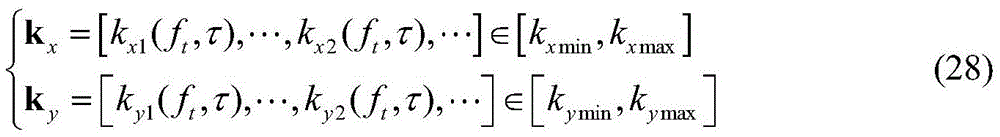
the resulting spatial spectral distribution is projected and the extent of this region can be defined as:
wherein k is x And k y Representing the spatial frequency vectors in the x and y directions, [ k ] xmin ,k xmax ]And [ k ] ymin ,k ymax ]Respectively represent k x And k y A value range in x and y directions, f t E B, B is the system bandwidth, τ E T a ;
Coherently projecting echo data to a spatial spectrum according to flight paths and system parameters of a master receiver and a slave receiver to obtain:
and thus a reconstructed point spread function:
wherein sigma (x, y) is a target scattering coefficient, and omega is a distribution range of a spatial spectrum;
step two: selecting a generalized bandwidth synthesis direction;
first, the spatial spectrum is along any direction φ i The circumscribed rectangular area of (2) is:
S r (φ i )=B ρf (φ i )·B ρf (φ i +π/2) (9)
wherein B is ρf (φ i ) And B ρf (φ i +pi/2) respectively represent the spatial spectrum at phi i And bandwidth projection in the orthogonal direction thereof;
then, defining a spatial spectral distribution at phi i The filling factor of the direction is:
wherein S is ω Representing the area of the spatial spectral distribution.
Finally, solving the maximum filling rate direction:
wherein I represents the number of projection segments transformed by complex Radon,
namely the generalized bandwidth synthesis direction, and the corresponding unit vector is:
orthogonal direction of->
The corresponding unit vectors are:
step three: projection correction of two-dimensional spatial spectrum data;
the spatial spectrum vector k of the formula (6) x And k y And (3) performing transformation:
wherein A is rot For the rotation matrix:
performing sine interpolation on echo data in a distance frequency domain to correct projection:
wherein,,
representing a two-dimensional Fourier transform, s (t, f
τ ) Representing the distance time-azimuth frequency domain echo after matched filtering, the echo s (t, f
τ ) Is of size N
r ×N
c ,N
r For distance to length, N
c Is the azimuth length; the size after the interpolation is M×L. At->
The spatial spectrum of the position, the coordinates after projection are:
wherein m=1, 2, …, M, l=1, 2, …, L, k'
x (e) And
respectively expressed in->
Edge->
And->
Spatial spectrum sampling coordinates of direction, Δk'
x And Δk'
y Respectively represent edge->
And->
Spatial spectral sampling interval of direction, (k'
xc ,k′
c ) A center coordinate representing a spatial spectral distribution;
step four: spatial spectrum extrapolation compensation based on the generalized matrix beam;
will k x The primary and secondary receiver echo data of the' direction are normalized:
wherein l
1 =1,2,…,L
1 ,l
2 =1,2,…,L
2 And l=l
1 +L
Δ +L
2 ,L
Δ Is the number of gap data, U represents the direction along the generalized bandwidth synthesis
The number of poles, a, of the all-pole model of (a)
u1 And a
u2 Representing signal amplitude, x'
u Representing the target in the generalized bandwidth synthesis direction +.>
The position of k'
x (l
1 ) And k'
x (l
2 ) Respectively representing the spatial spectrum, k 'of the main receiver and the secondary receiver after the projection correction in the step three'
Δx Indicating the phase difference between the gap signals, n
1 (l
1 ) And n
2 (l
2 ) Representing additive noise observed by the receiver.
By equation (18), the all-pole signal model is derived as:
wherein l=1, 2, …, L, a u Representing the signal amplitude, n (l) represents the additive noise observed by the receiver;
from s' 1 (l 1 ) And s' 2 (l 2 ) Respectively generating Hankel matrix H 1 And H 2 The following equation is obtained:
H 1 -λH 2 =0 (20)
wherein lambda is a generalized eigenvalue;
solving equation (20) to obtain the pair y (l) pole k' x (l) Is determined by the estimation of (a);
vandermonde matrix Z consisting of estimated U-order poles 1 The following equation is obtained:
wherein y= (y (1), …, y (l) 1 )) T Representing the echo data of the main receiver, solving the equation to obtain the y (l) amplitude a u According to the estimated pole k' x (l) Sum amplitude a u Obtaining an all-pole representation form of a signal model y (l) in the step (19), extrapolating a missing spatial spectrum of the distributed radar through the model, and fusing the missing spatial spectrum with the existing spatial spectrum to obtain a completed complete spatial spectrum;
step five: target reconstruction and geometric correction;
according to the complete spatial spectrum extrapolated in the fourth step, the target scattering coefficient may be expressed as:
wherein Ω' represents a complete spatial spectral distribution region;
obtaining an imaging result on an x-y plane through geometric correction of the following formula:
wherein (x, y) and (x ', y') represent the position coordinates of the object in the x-y and x '-y' planes, respectively,
is the inverse of the rotation matrix in step three equation (13).
The invention has the beneficial effects that: the spatial spectrum coherent fusion imaging method of the invention firstly establishes the geometric configuration of the distributed radar and analyzes the distributed radar echo coherent signal model; secondly, selecting a bandwidth synthesis direction according to the distribution shape of the echo spatial spectrum, and finishing the rotation of the spatial spectrum and the data projection correction; then, carrying out data coherent interpolation on the missing spatial spectrum by adopting a generalized matrix beam data extrapolation method, so as to realize the compensation of the split spatial spectrum of the distributed radar in a moving-unchanged mode; finally, mapping from the space spectrum domain to the target space domain is realized by adopting two-dimensional Fourier transformation, and a high-resolution imaging result is obtained through geometric correction. The imaging method of the invention carries out data compensation on the spatial spectrum of the radar echo by a matrix beam method to obtain a complete spatial spectrum, and then carries out Fourier transformation on the spatial spectrum to obtain a point spread function of the target, thus completing the reconstruction of the target. Under the condition of discontinuous sampling of spatial spectrum distribution, a high-resolution coherent fusion imaging result can be effectively reconstructed, high-resolution imaging of a target is realized, and the fusion imaging problem of the distributed radar split spatial spectrum under a moving unchanged mode is solved.
Detailed Description
The steps and results in the invention are verified on a MATLAB simulation platform, and specific implementation steps of the method are given below.
Step one: distributed radar echo signal model establishment
The system parameters adopted in this embodiment are shown in table 1, and a schematic diagram of the geometric model of the distributed radar imaging system is shown in fig. 2.
TABLE 1
| Parameters (parameters)
|
Numerical value
|
| Transmitter T position
|
(514km,0,11.2°)
|
| Main receiver R 1 Position of
|
(0,-10,2)km
|
| Slave receiver R 2 Relative position
|
(30,0,300)m
|
| Carrier frequency f c |
15GHz
|
| Signal bandwidth B
|
100MHz
|
| Sampling frequency f s |
150MHz
|
| Pulse repetition frequency PRF
|
500Hz
|
| Platform speed v
|
100m/s
|
| Synthetic aperture time T a |
8s
|
| All-pole model order U
|
5 |
The radar system comprises a transmitter and two receivers. Receiver 1 is the master receiver and receiver 2 is the slave receiver. Polar coordinates of transmitter position are
The primary receiver has European coordinates (x
1 ,y
1 ,H
1 ) The method comprises the steps of carrying out a first treatment on the surface of the The coordinate difference between the slave receiver and the master receiver is (deltax, deltay, deltaz); the main receiver flies to the reference object O with a speed of +.>
Wherein the method comprises the steps of
v indicates the speed direction and magnitude, respectively. Let the reference object O be located at the origin of coordinates (0, 0) and the observation object P be located at (x, y, 0). The transmitter radiates the broadband signal to observe the object point P, the echo data of which is matched and filtered with the echo data of the reference object O can obtain the distance frequency domain expression of the echo at the object point P as follows:
wherein f t Represents distance frequency, τ represents slow time, A represents echo amplitude, T a Represents the synthetic aperture time, K r Represents the tuning frequency, T r Represents the time width of the transmitted signal, c represents the speed of light, f c Representing the carrier frequency. History difference R 'between O and P' OP (τ) can be determined by the distance history R of the target P from the target O P1 And R is R O1 Expressed as:
the master receiver and the slave receiver in fig. 2 are respectively combined with a transmitter to form a double-base forward-looking synthetic aperture radar system. The spatial frequency of a dual-base synthetic aperture radar system consisting of a primary receiver and a transmitter can be expressed as:
wherein k is f =2π(f c +f t ) And/c represents the spatial frequency of the transmitted signal. Obtaining a spatial spectrum representation of the echo by coordinate projection:
s 1 (k x1 ,k y1 )=A·exp[j(xk x1 +yk y1 )] (27)
the range of the spatial spectrum distribution of the echo spatial spectrum is as follows:
wherein k is x And k y Representing spatial frequency vectors in the x and y directions, f t E B, B is the system bandwidth, τ E T a . Carrying out coherent projection on echoes of the main receiver and the auxiliary receiver to obtain a space spectrum of the multi-base forward-looking synthetic aperture radar, wherein the space spectrum is as follows:
the reconstructed point spread function is thus obtained:
wherein sigma (x, y) is a target scattering coefficient, and omega is a distribution range of a spatial spectrum.
Step two: generalized bandwidth synthesis direction selection
Based on the spatial spectrum distribution result of the one-to-two-to-one distributed radar obtained in the step (29), the generalized bandwidth synthesis direction phi needs to be calculated so as to perform subsequent spatial spectrum data extrapolation. First the spatial spectral edge phi i The circumscribed rectangular area of the direction is:
S r (φ i )=B ρf (φ i )·B ρf (φ i +π/2) (31)
in B of ρf (φ i ) And B ρf (φ i +pi/2) respectively represent the spatial spectrum at phi i And its bandwidth projection in the vertical direction.
To minimize extrapolated spatial spectral gaps, the spatial spectral distribution is calculated at φ i Filling factor of direction:
s in ω Representing the area of the spatial spectral distribution. The maximum filling rate direction is determined by:
where I represents the number of projection segments transformed by complex Radon. The unit vector corresponding to the maximum filling rate direction is the generalized bandwidth synthesis direction:
step three: projection correction of two-dimensional spatial spectral data
In the second step, the generalized spatial spectrum distribution rotation projection direction of the distributed radar is obtained, and when the accurate mapping of the spatial spectrum data along the projection direction is realized, the spatial spectrum data obtained by projection needs to be subjected to coordinate correction and aligned with the wave number vector.
First, the spatial spectrum vector k in (5) is calculated x And k y And (3) performing transformation:
wherein A is rot For the rotation matrix:
then, the projection is corrected by sinc interpolation of the distance frequency domain:
in the method, in the process of the invention,
representing a two-dimensional Fourier transform, s (t, f
τ ) Echo matched filtered data representing a distance time domain and a lateral distance frequency domain. Echo data size N
r ×N
c The interpolated data size is mxl. At->
Spatial spectrum at the position, coordinates after projection are:
where m=1, 2, …, M, l=1, 2, …, L, Δk' x And Δk' y Spatial spectrum sampling interval (k 'representing u and v directions, respectively)' xc ,k′ yc ) Representing the center coordinates of the spatial spectral distribution.
Step four: spatial spectrum extrapolation compensation based on generalized matrix beams
After the rotation of the spatial spectrum data and the correction of the projection coordinates are completed, the spatial spectrum data is projected to a new k' x -k′ y In the coordinate system. Will k' x The primary receiver and the secondary receiver echo data of the direction are normalized:
wherein, I 1 =1,2,…,L 1 ,l 2 =1,2,…,L 2 And l=l 1 +L Δ +L 2 ,L Δ Is the number of gap data, a u1 And a u2 Representing signal amplitude, n 1 And n 2 Representing the additive noise observed by the receiver, x' u Representing the position of the target in the generalized bandwidth synthesis direction, k' Δx Representing the phase difference between the gap data. The all-pole signal model is thus obtained as:
wherein l=1, 2, …, L, a u Representing the signal amplitude, n (l) represents the additive noise observed by the receiver.
From s' 1 (p 1 ) And s' 2 (p 2 ) Respectively generating Hanker matrix H 1 And H 2 The following equation is obtained:
H 1 -λH 2 =0 (41)
where λ is a generalized eigenvalue. Solving the equation can obtain the pair y (p) pole k' x An estimate of (p).
Vandermonde matrix Z consisting of estimated U-order poles 1 The following equation is obtained:
wherein y= (y (1), …, y (l) 1 )) T Representing the primary receiver echo data. Solving the equation to obtain the y (l) amplitude a u Is a function of the estimate of (2). From the estimated pole k' x (l) Sum amplitude a u An all-pole representation of the signal model y (l) in (17) is obtained from which the missing spatial spectrum of the distributed radar can be extrapolated.
Step five: target reconstruction and geometric correction
According to the complete spatial spectrum extrapolated in the fourth step, the target scattering coefficient may be expressed as:
where Ω' represents the complete spatial spectral distribution region. Obtaining an imaging result on an x-y plane through geometric correction:
where (x, y) and (x ', y') denote the position coordinates of the object in the x-y and x '-y' planes, respectively.
Based on the above steps, after the projection correction is completed on the acquired spatial spectrum data, the spatial spectrum data is shown in fig. 3 (a), the space after the spatial spectrum data is extrapolated can be compensated, and the result is shown in fig. 3 (b). When the traditional fast backward projection algorithm is adopted to carry out projection focusing on the acquired echo, the imaging result is shown in fig. 4 (a), and when the space spectrum acquired data has a gap, the problem of main lobe splitting can be generated by the imaging result, and ideal focusing can not be realized. When the traditional matrix Fourier transform method is used for imaging the spatial spectrum data, the imaging result is shown in fig. 4 (b), and the method can not solve the problem that main lobe splitting is generated in the spatial spectrum gap. The imaging result of the method is shown in fig. 4 (c), and in the result, it can be seen that the ideal focusing of the main lobe of the target can be realized, and the coherent fusion of the distributed radar under the condition of space spectrum splitting can realize the high-resolution focusing of the target.
According to the spatial spectrum coherent fusion imaging method of the distributed radar, disclosed by the invention, the spatial spectrum data is extrapolated by using a generalized matrix beam method, so that high-resolution imaging under the condition of spatial spectrum interruption can be realized, and the imaging performance of the distributed radar is improved.