Disclosure of Invention
In order to solve the problems in the prior art, the invention provides a method for restraining range ambiguity clutter and reducing dimension of an airborne FDA-MIMO bistatic radar.
One embodiment of the invention provides an airborne FDA-MIMO bistatic radar distance fuzzy clutter suppression and dimension reduction searching method, which comprises the following steps:
step 1, establishing a signal model, and obtaining radar clutter signals according to the signal model;
step 2, constructing a distance phase compensation guide vector, and performing primary clutter compensation processing on the radar clutter signal according to the distance phase compensation guide vector to obtain a first clutter processing signal;
step 3, performing second clutter compensation processing on the first clutter processing signal sequentially through a subspace projection technology and a DW technology to obtain a second clutter processing signal;
step 4, transmitting Doppler power spectrum scanning to obtain target Doppler and transmitting space angular frequency;
step 5, constructing a dimension reduction matrix by using the target Doppler and the emission space angular frequency;
and 6, performing dimension reduction search processing on the second clutter processing signal by using the dimension reduction matrix.
In one embodiment of the present invention, the radar clutter signals corresponding to the signal model established in step 1 are represented as:
wherein q represents the q-th distance fuzzy area in the power range, the number of the distance fuzzy areas is U, s
q Represents clutter signals corresponding to the qth range-blurred region,
s
p representing the p-th clutter blocks at a certain angle in the same distance fuzzy region, the total number of the p-th clutter blocks being N
c ,
Representing noise, γ
0 =exp{-j2πf
0 R
∑ C represents a common phase term, f
0 Denotes a reference frequency, R
∑ Representing the slope distance, c the speed of light, p
qp Representing the product of the scattering coefficient of the illuminated target and the signal propagation gain in the p-th clutter block in the q-th range ambiguity region, s
d Representing the Doppler steering vector, s
at Representing a transmit steering vector, f
d0qp Indicating the normalized Doppler frequency, f, of the p-th clutter block in the q-th range ambiguity region
atqp Represents the composite transmit spatial angular frequency, < > or < > of the p-th clutter block within the q-th range ambiguity region>
Representing the kronecker product.
In one embodiment of the present invention, the signal of the p-th spur block is represented as:
wherein, γ
0 =Υ
0q =exp{-j2πf
0 R
∑ /c},f
0 Denotes the reference frequency, R
∑ Denotes the slope distance, c denotes the speed of light, ρ denotes the product of the scattering coefficient of the illuminated object and the signal propagation gain, s
d Representing the Doppler steering vector, f
d0 Representing normalized Doppler frequency, d
r Indicating the spacing of the elements of the receiving array, #
r Representing the receiver array space cone angle, s
at Representing the steering vector of the received signal, f
at Representing the composite transmitted spatial angular frequency, s
R The phase term representing the coupling of the distance,
Δ f denotes the frequency increment, s
t Representing the transmit spatial steering vector, f
t Represents the spatial angular frequency of the emission, < > is selected>
Represents a noise +>
Indicating a kronecker product, which indicates a hadamard product.
In one embodiment of the present invention, the range-phase compensation steering vector constructed in step 2 is represented as:
wherein f is R0 Representing the angular frequency, R, of the range phase compensation Σ0 Indicating the slope distance of the non-blurred region.
In one embodiment of the present invention, the first clutter processing signal obtained by the first clutter compensation processing in step 2 is represented as:
wherein Y represents the radar clutter signal corresponding to the signal model,
representing a full column of vectors, f
Rqp Range phase compensation angular frequency, f, of the p-th clutter block representing an angle within the q-th range ambiguity region
tqp Representing the transmitted spatial angular frequency, R, of the p-th clutter block at an angle within the q-th range ambiguity region
u =c/f
prf Maximum unambiguous distance, f
prf Indicating the pulse repetition frequency.
In one embodiment of the present invention, step 3 comprises:
step 3.1, constructing a transmitting space frequency semi-positive definite matrix;
step 3.2, singular value decomposition is carried out on the transmitting space frequency semi-positive definite matrix, L eigenvectors corresponding to large eigenvalues are selected from decomposed eigenvalues, a subspace projection matrix is calculated according to the eigenvectors, and L is an integer larger than 0;
3.3, performing second clutter compensation processing on the first clutter processing signal according to the subspace projection matrix to obtain a clutter pre-processing signal;
and 3.4, compensating and aligning the clutter pre-processing signal through a DW technology to obtain the second clutter processing signal.
In one embodiment of the present invention, step 4 comprises:
and adopting an STAP method to transmit Doppler power spectrum scanning to obtain target Doppler and transmission space angular frequency.
In one embodiment of the present invention, the dimension reduction matrix constructed in step 5 is represented as:
wherein,
f
d0 representing the normalized Doppler frequency, f
t0 Representing the spatial angular frequency of transmission, f
r Representing the received spatial angular frequency, #
r The cone angle of the target and the receiving array is shown, M represents the number of array elements of the transmitting array, N represents the number of array elements of the receiving array, and K represents the number of coherent processing pulses.
In one embodiment of the present invention, step 6 comprises:
step 6.1, calculating a covariance matrix of the second clutter processing signal;
6.2, constructing a receiving angle estimation equation according to the covariance matrix and the dimension reduction matrix;
and 6.3, solving the receiving angle estimation equation to obtain an estimated target receiving angle.
In one embodiment of the invention, the receive angle estimation equation in step 6.2 is expressed as:
wherein, W T =T H W, W denotes a weight vector, T denotes a dimensionality reduction matrix, S T =T H S, S denotes the estimated target reception angle, R T =T H RT, R denotes covariance matrix, R = Y 2 Y 2 H 。
Compared with the prior art, the invention has the beneficial effects that:
according to the airborne FDA-MIMO bistatic radar distance fuzzy clutter suppression and dimension reduction searching method provided by the invention, the three-dimensional search of the transmitting space angular frequency, the receiving space angular frequency and the Doppler space of the traditional MIMO bistatic radar is divided into the two-dimensional search of the transmitting space angular frequency and the Doppler space, the distance fuzzy clutter suppression is carried out, the dimension reduction search is carried out in the receiving space after the target transmitting angle and the Doppler information are obtained, namely the three-dimensional search is divided into the searching form of '2 + 1', the requirement on the number of training samples is reduced, the algorithm complexity of self-adaptive weight calculation is reduced, and the influence of bistatic clutter distance coupling on the traditional STAP algorithm is reduced.
The present invention will be described in further detail with reference to the accompanying drawings and examples.
Detailed Description
The present invention will be described in further detail with reference to specific examples, but the embodiments of the present invention are not limited thereto.
Example one
Referring to fig. 1, fig. 1 is a schematic flow chart of a method for range ambiguity clutter suppression and dimension reduction search of an airborne FDA-MIMO bistatic radar according to an embodiment of the present invention. The embodiment provides a method for distance fuzzy clutter suppression and dimension reduction search of an airborne FDA-MIMO bistatic radar, which comprises the following steps:
step 1, establishing a signal model, and obtaining a radar clutter signal according to the signal model.
Specifically, referring to fig. 2, fig. 2 is a schematic diagram illustrating a geometric relationship between an airborne side view array FDA-MIMO bistatic radar transmit/receive array provided by an embodiment of the present invention, wherein in an (x, y, z) coordinate system, a transmit array is located at (b) L ,0,h t ) At (0, h), the receive array is located r ) Where h is t And h r Radar observation target P with transmitting and receiving array height i The distance from the transmitting array is set as R t And distance from the receiving array is set as R r Angular distance R Σ =R t +R r The space cone angle, azimuth angle and pitch angle of the target and the transmitting array are respectively set to psi t 、φ t 、θ t The space cone angle, azimuth angle and pitch angle of the target and receiving array are respectively set to psi r 、φ r 、θ r The number of array elements of the transmitting array is M, the number of array elements of the receiving array is N, and the spacing between the array elements is set as d t And d r . The motion speeds of the transmitting platform and the receiving platform are respectively v t And v r . In FDA-MIMO radar, at the carrier frequency f of the transmitted signal 0 As a reference frequency, the carrier frequency of each array element is at f 0 The same frequency increment Δ f is accumulated in turn on the basis of (1), and the transmission frequencies of the M array elements can be represented as:
f m =f 0 +(m-1)Δf m=1,…,M (1)
wherein, deltaf represents frequency increment, and (m-1) Deltaf represents the m-th array element relative to the carrier frequency f 0 And Δ f < f 0 . Similar to the conventional phased array radar, the narrow-band signal transmitted by the mth array element of the FDA-MIMO radar can be expressed as:
where rect (-) is a rectangular window function representing a signal pulse, T p Denotes the pulse width, s m (t) represents the orthogonal waveform of the m-th array element. When the ideal orthogonality condition is satisfied, there are:
then the narrow-band signal received by the target when the signal transmitted by equation (2) reaches the far field is represented as:
wherein, tau
t =R
t C and τ
sm =(m-1)d
t cosψ
t C represents the time delay, c represents the speed of light,
representing white Gaussian noise in the propagation process, which can be derived from FIG. 2>
f
dm =v
t cosψ
t f
m /c+v
r cosψ
r f
m C denotes f generated by platform movement
m Corresponding to the Doppler frequency, in equation (4), f is due to the velocity effect of the transmit array alone
dmt =v
t cosψ
t f
m And c, the ratio of the total weight to the total weight of the product. Since the radar transmits as a narrowband signal, there is s
m (t-τ
t -τ
sm )≈s
m (t-τ
t ),rect[(t-τ
t -τ
sm )/T
p ]≈rect[(t-τ
t )/T
p ]. After receiving the far-field reflected signal echo, the signal received by the nth array element is expressed as:
where ρ represents an irradiation radar observation target P i Product of scattering coefficient and signal propagation gain, τ Σ =(R t +R r )/c,τ sn =(n-1)d r cosψ r /c。
After reaching the target, the signal is reflected by the target and received by the receiving end array, and is processed by MIMO orthogonal waveform filtering. Specifically, the method comprises the following steps:
referring to fig. 3, fig. 3 is a schematic diagram of processing a received signal in an airborne FDA-MIMO bistatic radar distance ambiguity clutter suppression and dimension reduction search method according to an embodiment of the present invention, where x in fig. 3
n Representing the echo signal received by the nth receive channel,
the conjugate transpose of the orthogonal waveform corresponding to the mth transmitting channel is represented, and then the echo signal of the kth pulse received by the nth receiving channel transmitted by the mth transmitting channel of the FDA-MIMO bistatic radar is represented as: />
Wherein,f dm Denotes f dm Normalized Doppler frequency, f dm =f dm /f prf Y in formula (6) having a common phase term 0 =exp{-j2πf 0 R ∑ C, so equation (6) can be re-expressed as:
since Δ f < f
0 The phase term containing Δ f in the FDA-MIMO expression can be simplified to f
m =f
0 +(m-1)Δf
m ≈f
0 ,
Therefore, equation (7) is expressed as:
the coherent processing pulse number is K, and the receiving array element transmission array element is M and N respectively, and the space-time snap of this embodiment radar received signal is expressed as:
as shown by |' in the formula (9) indicates a hadamard product,
represents a kronecker product, -is present>
Doppler steering vector
Is shown as
s d (f d0 )=[1,exp{j2πf d0 },...,exp{j2π(K-1)f d0 }] T (10)
Wherein, [ ·]
T Representing transposed symbols. Receiving angle space guide vector of radar signal of the embodiment
Expressed as:
wherein,
the transmit steering vector of this embodiment is represented as:
s at (f at )=s R (f R )⊙s t (f t ) (12)
wherein, the phase component coupled with the distance generated by the frequency stepping amount in the transmitting guide vector is represented as:
wherein,
the transmit spatial angular frequency steering vector in the transmit steering vector is represented as:
in this embodiment, only echoes of all transmitting array elements received by one receiving channel are considered, and taking the first receiving channel as an example, a signal representation form of the p-th clutter block in a single range ambiguity region received is as follows:
wherein, upsilon
0 =exp{-j2πf
0 R
∑ C, being the common phase term, f
0 Denotes a reference frequency, R
∑ Representing the slope, c the speed of light, p the product of the scattering coefficient of the illuminated object and the signal propagation gain, s
d Representing the Doppler steering vector, f
d0 Representing normalized Doppler frequency, d
r Indicating the spacing of the elements of the receiving array, #
r Representing the receiver array space cone angle, s
at Representing the steering vector of the received signal, f
at Representing the composite transmitted spatial angular frequency, s
R The phase term representing the coupling of the distance,
Δ f denotes the frequency increment, s
t Representing the transmit spatial steering vector, f
t Represents the spatial angular frequency of the emission, < > is selected>
Represents noise and is greater or less>
Indicating a kronecker product, which indicates a hadamard product. As can be seen from equation (15), the signal steering vector received in the space-time snapshot has a distance steering vector component and a transmission angle steering vector component, that is: s is
at (f
at )=s
R (f
R )·s
t (f
t ) Wherein the first term s
R (f
R ) Distance-oriented vector of FDA, second term s
t (f
t ) The vector is directed for the launch angle. The signal echo comprises Doppler frequency and emission space angular frequency, and the distance coupling phase term s is contained in the emission space angular frequency of the FDA-MIMO radar
R (f
R ). In this embodiment, the radar clutter signals corresponding to the signal model received by the receiving channel are represented as:
y represents radar clutter signals corresponding to the signal model, q represents the q-th distance fuzzy area in the power range, the number of the distance fuzzy areas is U, and s
q Represents clutter signals corresponding to the qth range-blurred region,
s
p representing the p-th clutter blocks at a certain angle in the same distance fuzzy region, the total number of the p-th clutter blocks being N
c ,
Representing noise, γ
0q =Υ
0 =exp{-j2πf
0 R
∑ /c},f
0 Denotes the reference frequency, R
∑ Denotes the slope distance, c denotes the speed of light, ρ
qp Representing the product of the scattering coefficient of the illuminated target and the signal propagation gain in the p-th clutter block in the q-th range ambiguity region, s
d Representing the Doppler steering vector, s
at Representing a transmit steering vector, f
d0qp Indicating the normalized Doppler frequency, f, of the p-th clutter block in the q-th range ambiguity region
atqp A composite emission spatial angular frequency, <' > greater or less than the nth clutter block within the qth range ambiguity region>
Representing the kronecker product.
And 2, constructing a distance phase compensation guide vector, and performing primary clutter compensation processing on the radar clutter signals according to the distance phase compensation guide vector to obtain first clutter processing signals.
Specifically, in the present embodiment, by observing the formula (13) and the formula (14), it can be seen that s R (f R ) And s t (f t ) Have the same coefficient (m-1), and thus, can be obtained from equation (12):
as can be seen from equation (17), the range phase and the transmit spatial phase in the signal snapshot are in an uncoupled relationship with each other. Referring to fig. 4, fig. 4 is a geometric diagram illustrating a distribution geometry of clutter areas of an airborne FDA-MIMO bistatic radar provided in the embodiment of the present invention, in which a distance range to be observed is referred to as a distance ambiguity-free area and a distance ambiguity area, and the ambiguity area may be further divided into a first distance ambiguity area and a second distance ambiguity area. The emission guide space angular frequency corresponding to the range ambiguity region and the range ambiguity region in the FDA-MIMO bistatic radar is respectively written as:
wherein f is at0 Representing the transmitted spatial angular frequency, f, corresponding to the range-ambiguity-free region at1 Representing the angular frequency, R, of the steering vector of the first blurred region Σ And the distance of the corresponding area is represented, and U represents the maximum distance fuzzy area number in the power range of the bistatic radar. Since the radar echo strength is inversely proportional to the square of the propagation distance, the present embodiment takes the unambiguous region with a large echo strength and the first ambiguous region as an example for analysis, and it is known that the difference between the unambiguous region and the first ambiguous region is a maximum unambiguous distance R u Expressed as:
R Σ1 =R Σ0 +R u (19)
wherein R is u =c/f prf ,f prf Indicating the pulse repetition frequency. The phase difference of the guiding vector of the non-blur area and the first blur area of the present embodiment is expressed as:
from the observation of the formula (18) and the formula (20), it can be seen that the FDA-MIMO bistatic radar has one more distance coupling phase term compared with the traditional MIMO bistatic radar, and the adjacent distance is fuzzy and miscellaneousThe phase difference between the wave regions is Deltaf/f prf Therefore, although clutter echoes of the unambiguous region and the range-ambiguity region overlap each other in time, different range clutter positions are different in the transmission angle domain, and thus separation of the different range ambiguity clutter can be achieved. The second distance blurred region is similar to the first blurred region in processing, and detailed description thereof is omitted here.
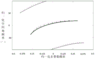
Under the condition that the bistatic transmit array receiving array has the same speed and the speed direction is parallel to the base line and the same height, please refer to fig. 5 (a) -5 (b), fig. 5 (a) -5 (b) are schematic diagrams of space-time clutter power spectrums of traditional MIMO and FDA-MIMO bistatic radars provided by the embodiments of the present invention, fig. 5 (a) is a power spectrum of space-time clutter of a traditional MIMO bistatic radar, fig. 5 (b) is a power spectrum of space-time clutter of an FDA-MIMO bistatic radar, and fig. 5 (a) -5 (b) respectively show three sampling range gates of a radar in a non-ambiguity region (R base) Σ =R Σ0 ) And a first blurred region (R) Σ =R Σ1 ) The clutter echo curve of (1), wherein the thicker dotted line, the dot-dash line, and the solid line (black solid line and three lines above) respectively represent the non-fuzzy region R Σ 60km,62km and 64km, the thinner dotted line, dot-dash line and solid line (grey solid line and three lines above) represent the three range gates corresponding to the first fuzzy region and the non-fuzzy region, R Σ 183km,185km,187km, respectively, the difference between two corresponding range gates of the same line type being one R u . It can be seen from fig. 5 (a) to 5 (b) that, due to the radar clutter distance coupling, the clutter in the unambiguous region and the first ambiguity distance clutter have different shapes, the distance ambiguity clutter overlaps in the MIMO bistatic radar shown in fig. 5 (a), and the distance coupling term in the FDA-MIMO bistatic radar shown in fig. 5 (b) shifts by-R in the transmission angle domain based on the clutter position of the original MIMO radar Σ Δ f/c, clutter of different regions corresponds to R Σ Different translation amounts are different, and the separation of the fuzzy clutters at different distances is realized. Therefore, for different fuzzy regions or non-fuzzy regions, the present embodiment performs phase compensation on the transmitting space oriented vector in the radar clutter signal by using the secondary distance compensation method (the first time)Clutter compensation), the constructed range-phase compensation steering vector is expressed as:
wherein f is R0 Representing the angular frequency, R, of the range phase compensation Σ0 Representing the slope distance of the non-blurred area.
Wherein,
is a full column vector. According to the distance phase compensation guiding vector, performing first clutter compensation processing on the radar clutter signals to obtain first clutter processing signals, wherein the first clutter processing signals are expressed as follows:
wherein, Y
1 Representing a first clutter processed signal, Y representing a radar clutter signal corresponding to the signal model,
representing a full column of vectors, f
Rqp Range phase compensation angular frequency, f, of the p-th clutter block representing an angle within the q-th range ambiguity region
tqp Representing the transmitted spatial angular frequency, R, of the p-th clutter block at an angle within the q-th range ambiguity region
u =c/f
prf ,f
prf Indicating the pulse repetition frequency. After the secondary distance clutter compensation (the first clutter compensation) according to the formula (23), please refer to fig. 6, where fig. 6 is a schematic diagram of a clutter power spectrum after the first clutter compensation processing of the airborne FDA-MIMO bistatic radar according to the embodiment of the present invention, as can be seen from fig. 6, a target is located in an unambiguous clutter region which is shifted to the center of the clutter spectrum, and other ambiguous clutter with multiple distances are offset from the clutter spectrumOn both sides.
And 3, sequentially carrying out second clutter compensation processing on the first clutter processing signal through a subspace projection technology and a DW technology to obtain a second clutter processing signal.
Specifically, in this embodiment, the subspace projection technique is used to perform the second clutter compensation processing on the first clutter processing signal, so as to remove the clutter in the distance blurred region and compensate and align the clutter in the non-blurred region, and the specific step 3 includes step 3.1, step 3.2, step 3.3, and step 3.4:
and 3.1, constructing a transmitting space frequency semi-positive definite matrix.
Specifically, the transmit spatial frequency semi-positive definite matrix constructed in the present embodiment is expressed as:
wherein, f t Representing the distribution of the unambiguous regions of interest at the emission spatial angular frequency.
And 3.2, carrying out singular value decomposition on the transmitting space frequency semi-positive definite matrix, selecting eigenvectors corresponding to L eigenvalues from the decomposed eigenvalues, and calculating a subspace projection matrix according to the eigenvectors, wherein L is an integer greater than 0.
Specifically, in this embodiment, singular value decomposition is performed on the transmit spatial frequency semi-positive definite matrix P, and the eigenvector U corresponding to the L decomposed large eigenvalues may be written as U = [ U ] 1 u 2 ... u L ]Then, the computation of the subspace projection matrix by the eigenvector U in this embodiment can be expressed as: η = UU H 。
And 3.3, performing second clutter compensation processing on the first clutter processing signal according to the subspace projection matrix to obtain a clutter pre-processing signal.
Specifically, in this embodiment, the second clutter compensation processing is performed on the first clutter processing signal according to the subspace projection matrix, and specifically, the first clutter processing signal is multiplied by the subspace projection matrix to obtain a clutter pre-processing signal for removing the clutter in the fuzzy region, which is expressed as:
Y 2 =ηY 1 =UU H Y 1 (25)
and 3.4, compensating and aligning the clutter pre-processing signal through a DW technology to obtain the second clutter processing signal.
Specifically, in this embodiment, after the distance fuzzy clutter is removed, the Doppler shift technique (DW for short) is used to align and compensate the clutter pre-processed signal to obtain a second clutter processed signal, so as to reduce the influence of the distance coupling of the clutter at different distances of the observation position on the adaptive weight.
And 4, transmitting Doppler power spectrum scanning to obtain the Doppler of the radar target and the transmitting space angular frequency.
Specifically, in this embodiment, an STAP method is used to scan the emission space and doppler domain emission doppler power spectrum of the bistatic to obtain two dimensions of information of target doppler and emission space angular frequency.
And 5, constructing a dimension reduction matrix by using the target Doppler and the emission space angular frequency.
Specifically, in this embodiment, a dimension reduction matrix is constructed by using the target doppler and the emission spatial angular frequency obtained in step 4, and the constructed dimension reduction matrix is represented as:
wherein,
f
d0 representing the normalized Doppler frequency, f
t0 Representing the spatial angular frequency of transmission, f
r Representing the received spatial angular frequency, #
r The cone angle of the target and the receiving array is shown, M represents the number of array elements of the transmitting array, N represents the number of array elements of the receiving array, and K represents the number of coherent processing pulses.
And 6, performing dimension reduction search processing on the second clutter processing signal by using the dimension reduction matrix.
Specifically, step 6 in this embodiment includes:
6.1, calculating a covariance matrix of the second clutter processing signal;
step 6.2, constructing a receiving angle estimation equation according to the covariance matrix and the dimension reduction matrix;
and 6.3, solving the receiving angle estimation equation to obtain a specific estimated target receiving angle.
Specifically, in this embodiment, the second clutter processing signal is obtained in step 3, and the covariance matrix R = Y of the second clutter processing signal is calculated 2 Y 2 H And constructing a receiving angle estimation equation according to the dimension reduction matrix and the covariance matrix R obtained in the step 5, wherein the specific receiving angle estimation equation is expressed as:
wherein, W T =T H W, W denotes a weight vector, T denotes a dimensionality reduction matrix, S T =T H S, S denotes the estimated target reception angle, R T =T H RT, R denotes covariance matrix, R = Y 2 Y 2 H . And performing one-dimensional search in a receiving space angular frequency domain, namely solving the receiving angle estimation equation to obtain an estimated target receiving angle.
In order to verify the effectiveness of the method for distance ambiguity clutter suppression and dimension reduction search of the airborne FDA-MIMO bistatic radar proposed in this embodiment, the following simulation experiment is used to further prove the effectiveness.
And (4) aiming at fuzzy areas with different distances, the echo power spectrums under different radar structures are simulated and compared. The simulation parameters of the bistatic radar in the simulation process of the embodiment are shown in table 1.
TABLE 1 bistatic radar simulation parameters
Simulation 1:
referring to fig. 7 (a) -7 (b), fig. 7 (a) -7 (b) are schematic CAPON scanning power spectra of conventional phased array radar and FDA-MIMO bistatic radar in doppler and emission angle dimensions according to an embodiment of the present invention. As can be seen from the simulation of FIGS. 7 (a) to 7 (b), in the non-blurred region R Σ0 =60km and a first distance-blurred region R Σ1 And clutter echoes exist at positions of 183km, and clutter is distributed in an inclined curve due to the geometric position relation of the bistatic radar. FIG. 7 (a) is a clutter scanning power spectrum of a conventional phased array radar, and it can be seen that clutter has a distance-dependent characteristic, clutter echoes at different distances have different shapes, and although clutter at two distances are overlapped, the emission angular frequency f at the emission normalization is t =0.2 and normalized doppler f d The pits existing due to different clutter shapes of different fuzzy areas can be seen near = 0.15; FIG. 7 (b) is the FDA-MIMO radar clutter scan power spectrum, which shows the unambiguous region R in FIG. 7 (b) Σ0 Clutter of (2) and the first blurred region R Σ1 Due to the existence of FDA-MIMO distance coupling phase terms, the fuzzy region R is eliminated Σ0 A first blur region R Σ1 The clutter of two regions are separated from each other, wherein, at f t =[-1,0]Range is clutter without ambiguity, at f t =[0,1]The range is the first fuzzy region clutter. Referring to fig. 8 (a) -8 (b), fig. 8 (a) -8 (b) are schematic diagrams of a CAPON scanning power spectrum of the FDA-MIMO bistatic radar in different stages according to the exemplary embodiment of the present invention, in which fig. 7 (b) is obtained by translating the unambiguous clutter in the observation region to the center of the clutter spectrum through the first clutter compensation to obtain fig. 8 (a), which is located at f t =[-0.6,0.6]The echo in the region is the unambiguous region described in this example, and then f is constructed by orthogonal subspace projection techniques according to equation (24) t =[-0.6,0.6]The spatial projection matrix eta, the clutter in the distance fuzzy region is removed by the orthogonal subspace projection technology through the formula (25) to obtain the graph (d) in FIG. 8, as can be seen from the graph (d) in FIG. 8, the clutter gain of the first fuzzy region is suppressed, and is changed from-20 dB to-30 dB to-38 dB to-50 dB, andcompared with the traditional phased array bistatic radar, the method provided by the invention can realize complete separation of fuzzy clutter in different area distances and has an effective suppression effect.
Simulation 2:
referring to fig. 9, fig. 9 is a schematic diagram of IF curves of airborne bistatic radars under different methods according to an embodiment of the present invention, in this embodiment, the radar Improvement Factor (IF) index is used to compare the range ambiguity clutter suppression effect and the dimension reduction search effect under different methods, and specifically, fig. 9 corresponds to a normalized angular frequency f t An improvement factor IF curve for clutter spectrum of 0.16, the IF curve being an indicator for assessing radar effectiveness, defined as the ratio of the signal to noise ratio of the output to the input:
wherein,
represents the power of the output signal, is greater than or equal to>
Represents the power of the input signal, is greater than or equal to>
Which is indicative of the power of the output noise,
representing the input noise power, s the signal vector, w the receiver steering vector, Q the noise covariance matrix, tr (·) the traces of the matrix, (·)
* Indicating taking the conjugate.
As can be seen from fig. 9: as can be seen from the IF curve before DW compensation of the two radars, the curve in the conventional phased array radar has two notches at-0.2 and 0.16 due to clutter echoes of the unambiguous region and the first ambiguous region, wherein the notch at-0.2 is caused by clutter of the unambiguous region and the notch at 0.16 is caused by the distance from the first ambiguous region to the ambiguity clutterThe distance fuzzy clutter has distance dependency, so that two clutter ridges in different areas have different shapes and are mutually overlapped, and as can be seen from fig. 9, the Doppler domain detection performance of the radar is seriously reduced at a clutter notch and at the peripheral position of the clutter notch, so that the more the clutter notches are, the larger the polluted detection area is; for the traditional phased array bistatic radar, the performance is obviously reduced due to the influence of clutter distance coupling and fuzzy clutter overlapping of distances in different areas; the method provided by the invention inhibits fuzzy distance clutter outside the non-observation area, and the observation of the dot-dash line shows that the IF curve of the FDA-MIMO bistatic radar has only one notch at the position of-0.2, which is caused by the clutter in the non-fuzzy area, and the performance loss depression width is smaller than that of the traditional STAP method. The result shows that the method can obviously reduce the overlapping phenomenon of the radar distance fuzzy clutter in the power spectrum and inhibit the distance fuzzy clutter. In fig. 9, the coil and the cross line are a comparison graph of the IF curves of the radar after compensation by the DW method, and the coil in the graph is the IF curve of the conventional phased array bistatic radar after compensation by the DW method, and because of the existence of distance fuzzy clutter, there is no fuzzy area clutter (f) d = 0.2) and range-blurred region clutter (f) d = 0.16), the compensation results in that the clutter broadening phenomenon in the non-fuzzy region is suppressed, the position of the notch of the curve is changed from 0.16 to 0.12 after DW compensation, two notches still exist in the IF curve, and the performance of the region between the notches is also influenced by the notches. And because the distance fuzzy clutter of the cross-line FDA-MIMO bistatic radar IF curve is suppressed, clutter broadening is suppressed after the IF curve of only one notch is compensated by a DW method, and the detection performance is obviously improved compared with that of the traditional phased array bistatic radar.
Referring to fig. 10, fig. 10 is a schematic diagram of a three-dimensional structure of clutter ridges in a transmitting angle domain, a receiving angle domain and a doppler domain of an FDA-MIMO bistatic radar unambiguous region provided by an embodiment of the present invention, where four types of lines, such as an asterisk line, a circle line, a triangle line and a cross line, are selected to respectively represent R Σ0 The distance gates are 60km, 183km, 306km and 429km corresponding to the ridge of the clutter. In the MISO stage of the preceding bistatic, by clutter suppression and adaptationSearching the doppler and emission angle information of the obtained target, constructing a dimension reduction matrix according to the two-dimensional information and formulas (26) and (27) to perform dimension reduction search on the three-dimensional structure of the FDA-MIMO bistatic radar, referring to fig. 11, fig. 11 is a view showing the emission angular frequency f in the three-dimensional structure of the FDA-MIMO bistatic radar according to the embodiment of the present invention t And when the clutter is not less than 0.16, a two-dimensional CAPON power spectrum diagram of a Doppler domain receiving angle domain of the clutter is obtained, and dimension reduction search is performed on the three-dimensional FDA-MIMO bistatic radar signal by combining Doppler information of an expected target.
Simulation 3:
referring to fig. 12 (a) -12 (b), fig. 12 (a) -12 (b) are schematic diagrams comparing IF curves of performance of the dimension reduction search method provided by the present invention and the conventional 3DT dimension reduction method when the number of training samples provided by the embodiment of the present invention is 300 and 800, respectively, in this embodiment, the effectiveness of the invention is described by performance of radar under different numbers of training samples, specifically: fig. 12 (a) -12 (b) show IF curve comparison graphs of the performance of the dimensionality reduction search method of the present invention and the traditional 3DT dimensionality reduction method when the number of training samples is 300 and 800, respectively, and the performance curve of the ideal full-dimensional adaptive method when the training samples are sufficient is marked in the graphs as a reference (the ideal training sample number is 1536 according to the RMB criterion). As can be seen from FIGS. 12 (a) -12 (b), the dimension reduction method and the 3DT dimension reduction method proposed by the present invention have clutter present (normalized Doppler frequency f) under two different sample numbers d = 0.24), all are smaller than the ideal case, while at other doppler positions, the method of the invention is better than the 3DT dimension reduction method, compared to the curve of the ideal case, while it can be seen that the difference between the performance of the 3DT dimension reduction method and the method of the invention decreases as the number of samples increases. Referring to FIG. 13, FIG. 13 shows an example of traversal of training samples in 300, 800]In the range of f t =0.16、f d =-0.56、 f r The comparison schematic diagram of IF curves corresponding to different methods of =0-0.288, the method provided by the present invention, the 3DT dimension reduction method and the common full-dimensional adaptive method are represented by a star line, a dot-dash line and a triangular line respectively, and as can be seen from fig. 13, the number of samples is far lower than two times of that of the radarUnder the condition of freedom degree, the radar detection performance of the common full-dimensional self-adaptive method is the lowest, the performance of the method and the 3DT dimension reduction method is increased along with the increase of the number of samples, and the method is superior to the 3DT dimension reduction method under the condition that the number of the samples is not changed, and the result is consistent with the results of the graphs 12 (a) -12 (b). Therefore, as can be seen from fig. 13, in the case of a rare number of training samples, the performance of the common full-dimensional adaptive method is the lowest among the three methods, and then the 3DT dimension reduction method is the most preferable.
In summary, the airborne FDA-MIMO bistatic radar distance fuzzy clutter suppression and dimension reduction search method provided in this embodiment splits three-dimensional search of the transmitting space angular frequency, the receiving space angular frequency, and the doppler space of the conventional MIMO bistatic radar into two-dimensional search of the transmitting space angular frequency and the doppler space, performs distance fuzzy clutter suppression, and performs dimension reduction search in the receiving space after obtaining the target transmitting angle and the doppler information, that is, the three-dimensional search is split into a search form of "2+1", which reduces the requirement on the number of training samples, reduces the algorithm complexity of adaptive weight calculation, reduces the influence of bistatic clutter distance coupling on the conventional STAP algorithm, and improves the detection performance of the conventional STAP algorithm under the condition that training samples are not distributed in an independent system of bistatic radar; meanwhile, the FDA radar inhibits the pollution of the range fuzzy clutter on a radar detection area, so that the bistatic radar has better parameter estimation capability.
The foregoing is a more detailed description of the invention in connection with specific preferred embodiments and it is not intended that the invention be limited to these specific details. For those skilled in the art to which the invention pertains, several simple deductions or substitutions can be made without departing from the spirit of the invention, and all shall be considered as belonging to the protection scope of the invention.