CN113137778B - Cogeneration system with no moving parts - Google Patents
Cogeneration system with no moving parts Download PDFInfo
- Publication number
- CN113137778B CN113137778B CN202010056358.1A CN202010056358A CN113137778B CN 113137778 B CN113137778 B CN 113137778B CN 202010056358 A CN202010056358 A CN 202010056358A CN 113137778 B CN113137778 B CN 113137778B
- Authority
- CN
- China
- Prior art keywords
- heat exchanger
- thermoacoustic
- thermomagnetic
- core unit
- tube
- Prior art date
- Legal status (The legal status is an assumption and is not a legal conclusion. Google has not performed a legal analysis and makes no representation as to the accuracy of the status listed.)
- Active
Links
- 238000010248 power generation Methods 0.000 claims abstract description 45
- 238000001816 cooling Methods 0.000 claims abstract description 39
- 238000010438 heat treatment Methods 0.000 claims abstract description 30
- 239000000463 material Substances 0.000 claims description 51
- 230000005291 magnetic effect Effects 0.000 claims description 30
- 239000004020 conductor Substances 0.000 claims description 12
- 239000007788 liquid Substances 0.000 claims description 10
- 239000007789 gas Substances 0.000 claims description 9
- XKRFYHLGVUSROY-UHFFFAOYSA-N Argon Chemical compound [Ar] XKRFYHLGVUSROY-UHFFFAOYSA-N 0.000 claims description 4
- IJGRMHOSHXDMSA-UHFFFAOYSA-N Atomic nitrogen Chemical compound N#N IJGRMHOSHXDMSA-UHFFFAOYSA-N 0.000 claims description 4
- CURLTUGMZLYLDI-UHFFFAOYSA-N Carbon dioxide Chemical compound O=C=O CURLTUGMZLYLDI-UHFFFAOYSA-N 0.000 claims description 4
- XLYOFNOQVPJJNP-UHFFFAOYSA-N water Substances O XLYOFNOQVPJJNP-UHFFFAOYSA-N 0.000 claims description 4
- 239000012530 fluid Substances 0.000 claims description 3
- 238000005057 refrigeration Methods 0.000 claims description 3
- 229910052786 argon Inorganic materials 0.000 claims description 2
- 239000001569 carbon dioxide Substances 0.000 claims description 2
- 229910002092 carbon dioxide Inorganic materials 0.000 claims description 2
- 239000001307 helium Substances 0.000 claims description 2
- 229910052734 helium Inorganic materials 0.000 claims description 2
- SWQJXJOGLNCZEY-UHFFFAOYSA-N helium atom Chemical compound [He] SWQJXJOGLNCZEY-UHFFFAOYSA-N 0.000 claims description 2
- 229910001338 liquidmetal Inorganic materials 0.000 claims description 2
- 229910052757 nitrogen Inorganic materials 0.000 claims description 2
- 238000011084 recovery Methods 0.000 claims 2
- 230000000694 effects Effects 0.000 abstract description 4
- 239000000498 cooling water Substances 0.000 description 11
- 230000004907 flux Effects 0.000 description 6
- 238000002485 combustion reaction Methods 0.000 description 5
- 238000005516 engineering process Methods 0.000 description 5
- 238000010586 diagram Methods 0.000 description 4
- 239000000446 fuel Substances 0.000 description 3
- 238000004519 manufacturing process Methods 0.000 description 3
- 238000000034 method Methods 0.000 description 3
- 230000008901 benefit Effects 0.000 description 2
- 230000007423 decrease Effects 0.000 description 2
- 230000005294 ferromagnetic effect Effects 0.000 description 2
- 230000006698 induction Effects 0.000 description 2
- 238000012423 maintenance Methods 0.000 description 2
- VNWKTOKETHGBQD-UHFFFAOYSA-N methane Chemical compound C VNWKTOKETHGBQD-UHFFFAOYSA-N 0.000 description 2
- 230000010355 oscillation Effects 0.000 description 2
- 230000005298 paramagnetic effect Effects 0.000 description 2
- 230000035699 permeability Effects 0.000 description 2
- 230000008569 process Effects 0.000 description 2
- 238000012545 processing Methods 0.000 description 2
- 230000002441 reversible effect Effects 0.000 description 2
- 229910000976 Electrical steel Inorganic materials 0.000 description 1
- 238000006243 chemical reaction Methods 0.000 description 1
- 238000010276 construction Methods 0.000 description 1
- 238000011161 development Methods 0.000 description 1
- 230000007613 environmental effect Effects 0.000 description 1
- 230000005307 ferromagnetism Effects 0.000 description 1
- 238000009434 installation Methods 0.000 description 1
- 230000002427 irreversible effect Effects 0.000 description 1
- 239000000696 magnetic material Substances 0.000 description 1
- 238000012986 modification Methods 0.000 description 1
- 230000004048 modification Effects 0.000 description 1
- 239000003345 natural gas Substances 0.000 description 1
- 239000003921 oil Substances 0.000 description 1
- 230000005408 paramagnetism Effects 0.000 description 1
- 230000001902 propagating effect Effects 0.000 description 1
- 238000007789 sealing Methods 0.000 description 1
- 239000004449 solid propellant Substances 0.000 description 1
Images


Classifications
-
- F—MECHANICAL ENGINEERING; LIGHTING; HEATING; WEAPONS; BLASTING
- F25—REFRIGERATION OR COOLING; COMBINED HEATING AND REFRIGERATION SYSTEMS; HEAT PUMP SYSTEMS; MANUFACTURE OR STORAGE OF ICE; LIQUEFACTION SOLIDIFICATION OF GASES
- F25B—REFRIGERATION MACHINES, PLANTS OR SYSTEMS; COMBINED HEATING AND REFRIGERATION SYSTEMS; HEAT PUMP SYSTEMS
- F25B23/00—Machines, plants or systems, with a single mode of operation not covered by groups F25B1/00 - F25B21/00, e.g. using selective radiation effect
-
- F—MECHANICAL ENGINEERING; LIGHTING; HEATING; WEAPONS; BLASTING
- F03—MACHINES OR ENGINES FOR LIQUIDS; WIND, SPRING, OR WEIGHT MOTORS; PRODUCING MECHANICAL POWER OR A REACTIVE PROPULSIVE THRUST, NOT OTHERWISE PROVIDED FOR
- F03G—SPRING, WEIGHT, INERTIA OR LIKE MOTORS; MECHANICAL-POWER PRODUCING DEVICES OR MECHANISMS, NOT OTHERWISE PROVIDED FOR OR USING ENERGY SOURCES NOT OTHERWISE PROVIDED FOR
- F03G7/00—Mechanical-power-producing mechanisms, not otherwise provided for or using energy sources not otherwise provided for
- F03G7/06—Mechanical-power-producing mechanisms, not otherwise provided for or using energy sources not otherwise provided for using expansion or contraction of bodies due to heating, cooling, moistening, drying or the like
-
- H—ELECTRICITY
- H02—GENERATION; CONVERSION OR DISTRIBUTION OF ELECTRIC POWER
- H02N—ELECTRIC MACHINES NOT OTHERWISE PROVIDED FOR
- H02N11/00—Generators or motors not provided for elsewhere; Alleged perpetua mobilia obtained by electric or magnetic means
- H02N11/002—Generators
-
- Y—GENERAL TAGGING OF NEW TECHNOLOGICAL DEVELOPMENTS; GENERAL TAGGING OF CROSS-SECTIONAL TECHNOLOGIES SPANNING OVER SEVERAL SECTIONS OF THE IPC; TECHNICAL SUBJECTS COVERED BY FORMER USPC CROSS-REFERENCE ART COLLECTIONS [XRACs] AND DIGESTS
- Y02—TECHNOLOGIES OR APPLICATIONS FOR MITIGATION OR ADAPTATION AGAINST CLIMATE CHANGE
- Y02E—REDUCTION OF GREENHOUSE GAS [GHG] EMISSIONS, RELATED TO ENERGY GENERATION, TRANSMISSION OR DISTRIBUTION
- Y02E20/00—Combustion technologies with mitigation potential
- Y02E20/14—Combined heat and power generation [CHP]
Landscapes
- Engineering & Computer Science (AREA)
- Chemical & Material Sciences (AREA)
- Combustion & Propulsion (AREA)
- Mechanical Engineering (AREA)
- General Engineering & Computer Science (AREA)
- Physics & Mathematics (AREA)
- Thermal Sciences (AREA)
- Connection Of Motors, Electrical Generators, Mechanical Devices, And The Like (AREA)
Abstract
一种无运动部件的冷热电联供系统,包括至少一个热声发动机核心单元、至少一热磁发电单元和至少一个热声制冷机核心单元;所述热声发动机核心单元用于将热能转化为声波形式的机械能;所述热磁发电单元连接于所述热声发动机核心单元的一侧并用于将经过热磁发电单元的声波形式的机械能的其中一部分转化为电能;所述热声制冷机核心单元连接于所述热声发动机核心单元的一侧并用于将经过热磁发电单元后的声波形式的机械能用于制冷。本发明利用热声发动机产生压力波动,利用热磁发电单元将外部热能转化为电能输出;另一部分声功被热声制冷机消耗,产生制冷效应,不存在机械运动部件,因此其可靠性高、结构结单。

A combined cooling, heating and power system without moving parts, comprising at least one thermoacoustic engine core unit, at least one thermomagnetic power generation unit, and at least one thermoacoustic refrigerator core unit; the thermoacoustic engine core unit is used to convert thermal energy It is mechanical energy in the form of sound waves; the thermo-magnetic power generation unit is connected to one side of the core unit of the thermoacoustic engine and is used to convert a part of the mechanical energy in the form of sound waves passing through the thermo-magnetic power generation unit into electrical energy; the thermoacoustic refrigerator The core unit is connected to one side of the core unit of the thermoacoustic engine and is used for cooling the mechanical energy in the form of sound wave after passing through the thermomagnetoelectric unit. The invention utilizes a thermoacoustic engine to generate pressure fluctuations, and utilizes a thermomagnetic power generation unit to convert external heat energy into electric energy output; another part of the sound work is consumed by a thermoacoustic refrigerator to produce a cooling effect, and there are no mechanical moving parts, so its reliability is high, Structure statement.
Description
技术领域technical field
本发明涉及冷热电联供技术领域,特别是涉及一种无运动部件的冷热电联供系统。The invention relates to the technical field of cogeneration of cooling, heating and power, in particular to a cogeneration system of cooling, heating and power without moving parts.
背景技术Background technique
冷热电联供(Combined Cooling Heating and Power,CCHP)系统是一种建立在能源梯级利用概念基础上,集制冷、供热(采暖和供热水)及发电过程为一体的多能联供总能系统,总的能源利用率可以达到75%—90%以上。与传统分供式能源系统相比较,冷热电联供系统结构紧凑,占地面积小,安装方便,维护简单,自动化程度高,运行成本低。与大电网、集中式供能系统相比,冷热电联供系统还具有投资小、见效快等特点,代表着当前能源利用新的发展方向。Combined Cooling Heating and Power (CCHP) system is based on the concept of energy cascade utilization and integrates refrigeration, heating (heating and hot water supply) and power generation. Energy system, the total energy utilization rate can reach more than 75% -90%. Compared with the traditional distributed energy system, the combined cooling, heating and power system has a compact structure, a small footprint, easy installation, simple maintenance, a high degree of automation, and low operating costs. Compared with large power grids and centralized energy supply systems, combined cooling, heating and power systems also have the characteristics of small investment and quick results, representing a new development direction for current energy utilization.
现有冷热电联供系统按原动机类型分类,可分为蒸汽轮机系统、燃气轮机系统、内燃机系统、斯特林发动机系统、微型燃气轮机系统及燃料电池系统等。其中,蒸汽轮机系统、燃气轮机系统主要用在大型的热电联供场合;斯特林发动机、燃料电池和微型燃气轮机目前还不具备可靠的制造技术,且系统建设成本较高。基于内燃机的冷热电联供技术是目前较为成熟的冷热电联供技术。内燃机的功率范围较广,发电效率可达30%以上,热电综合效率可达90%,初投资成本较低,但是其对燃料种类要求高,且噪音较大。此外,由于活塞、连杆、曲轴、飞轮等运动部件的存在,内燃机的可靠性较低,需定期维护保养。The existing combined cooling, heating and power systems are classified according to the type of prime mover, and can be divided into steam turbine systems, gas turbine systems, internal combustion engine systems, Stirling engine systems, micro gas turbine systems, and fuel cell systems. Among them, steam turbine system and gas turbine system are mainly used in large-scale combined heat and power; Stirling engine, fuel cell and micro gas turbine do not yet have reliable manufacturing technology, and the system construction cost is relatively high. The combined cooling, heating and power technology based on the internal combustion engine is a relatively mature combined cooling, heating and power technology at present. The power range of the internal combustion engine is relatively wide, the power generation efficiency can reach more than 30%, and the comprehensive thermoelectric efficiency can reach 90%. The initial investment cost is low, but it has high requirements for fuel types and is noisy. In addition, due to the existence of moving parts such as pistons, connecting rods, crankshafts, and flywheels, internal combustion engines have low reliability and require regular maintenance.
当一个管道中存在适当的温度梯度和声场时,声波振荡就会自发产生,将热能转化成声波形式的机械能,这就是热致声效应。热声发动机作为一种新型外燃式热机,它利用热致声效应将热能转化为声能,具有无机械运动部件带来的运行可靠和长寿命、潜在热效率高和环境友好等优点。根据热声转换的声场特性,热声发动机可分为行波热声发动机和驻波热声发动机,两者各有优势:驻波热声发动机板叠内的热交换过程基于不可逆过程、热效率略低,但是其具有结构简单的优点;相比于基于不可逆循环的驻波热声发动机而言,行波热声发动机基于可逆的斯特林循环,潜在热效率更高。When an appropriate temperature gradient and sound field exist in a pipe, acoustic oscillations are spontaneously generated, converting thermal energy into mechanical energy in the form of acoustic waves, which is the thermoacoustic effect. As a new type of external combustion heat engine, thermoacoustic engine uses thermoacoustic effect to convert heat energy into sound energy. It has the advantages of reliable operation and long life without mechanical moving parts, high potential thermal efficiency and environmental friendliness. According to the sound field characteristics of thermoacoustic conversion, thermoacoustic engines can be divided into traveling wave thermoacoustic engines and standing wave thermoacoustic engines. Low, but it has the advantage of simple structure; compared with the standing wave thermoacoustic engine based on the irreversible cycle, the traveling wave thermoacoustic engine is based on the reversible Stirling cycle, and the potential thermal efficiency is higher.
图1所示为现有技术公开号为CN 103835903B的中国发明专利提供了一种行波热声冷热电联供系统,其由至少三台行波热声发动机2、至少一台行波热声制冷机3和直线电机及4谐振单元1组成;行波热声发动机通过谐振单元首尾相连构成环路;行波热声制冷机一端旁接于谐振单元,另一端与直线发电机相连;系统通过行波热声发动机将热能转化成声功,行波热声制冷机利用一部分声功实现制冷,直线发电机将制冷机出口声功转化为电能,并为行波热声制冷机提供适合的相位,提高制冷机性能;各发动机的冷却水温度升高用于生活供热。但发明人在实际应用中发现,该系统虽然具有很好的热源适应性,可以利用天然气、各种液体固体燃料,也可以利用太阳能,但该系统存在下述问题:首先,直线发电机的气缸413与活塞412之间必须采用高精度的间隙密封技术,这对零部件的加工制造和装配提出了严苛的要求,进而会增加该行波热声冷热电联供系统的生产制造成本;其次,由于该行波热声冷热电联供系统引入了活塞412、动子磁铁415等机械运动部件,由于这些机械运动部件的存在,大大降低了该行波热声冷热电联供系统的可靠性并缩短了其使用寿命。Figure 1 shows that the Chinese invention patent with the prior art publication number CN 103835903B provides a traveling wave thermoacoustic cogeneration system, which consists of at least three traveling wave thermoacoustic engines 2, at least one traveling wave thermoacoustic The acoustic refrigerator 3 is composed of a linear motor and a resonance unit 1; the traveling wave thermoacoustic engine is connected end to end through the resonance unit to form a loop; one end of the traveling wave thermoacoustic refrigerator is connected to the resonance unit, and the other end is connected to the linear generator; the system The thermal energy is converted into sound work through the traveling wave thermoacoustic engine, and the traveling wave thermoacoustic refrigerator uses part of the sound work to achieve cooling. phase, improve the performance of the refrigerator; the cooling water temperature of each engine is raised for domestic heating. However, the inventor found in practical applications that although the system has good heat source adaptability and can utilize natural gas, various liquid solid fuels, and solar energy, the system has the following problems: First, the cylinder of the linear generator High-precision gap sealing technology must be used between 413 and
发明内容Contents of the invention
本发明基于现有技术存在的问题提出,旨在解决现有技术存在机械运动部件,因此其可靠性低、结构复杂、对加工工艺要求高、生产成本高的难题,提供一种无运动部件的冷热电联供系统。The present invention is proposed based on the problems existing in the prior art, and aims to solve the problems of low reliability, complex structure, high requirements on processing technology and high production cost due to the existence of mechanical moving parts in the prior art, and provides a kind of machine without moving parts. Combined heating and cooling system.
本发明提供一种无运动部件的冷热电联供系统,包括至少一个热声发动机核心单元、至少一热磁发电单元和至少一个热声制冷机核心单元;所述热声发动机核心单元用于将热能转化为声波形式的机械能;所述热磁发电单元连接于所述热声发动机核心单元的一侧并用于将经过热磁发电单元的声波形式的机械能的其中一部分转化为电能;所述热声制冷机核心单元连接于所述热声发动机核心单元的一侧并用于将经过热磁发电单元后的未转化电能的声波形式的机械能用于制冷。The present invention provides a combined cooling, heating and power system without moving parts, comprising at least one thermoacoustic engine core unit, at least one thermomagnetic power generation unit, and at least one thermoacoustic refrigerator core unit; the thermoacoustic engine core unit is used for converting thermal energy into mechanical energy in the form of sound waves; the thermomagnetic power generation unit is connected to one side of the core unit of the thermoacoustic engine and used to convert a part of the mechanical energy in the form of sound waves passing through the thermomagnetic power generation unit into electrical energy; The core unit of the acoustic refrigerator is connected to one side of the core unit of the thermoacoustic engine, and is used for cooling the mechanical energy in the form of sound waves, which are not converted into electric energy after passing through the thermomagnetic power generation unit.
本发明利用热声发动机产生压力波动,消耗一部分声功(声波形式的机械能)推动U形谐振管中的液体往复运动,进而利用热磁发电单元将外部热能转化为电能输出。另一部分声功被热声制冷机消耗,产生制冷效应。同时热声发动机、热声制冷机和热磁发电单元的室温端换热器释放给冷却水的热量用于供热,不存在机械运动部件,因此其可靠性高、结构结单。The invention uses a thermoacoustic engine to generate pressure fluctuations, consumes part of the sound work (mechanical energy in the form of sound waves) to push the liquid in the U-shaped resonant tube to reciprocate, and then uses a thermomagnetic power generation unit to convert external heat energy into electrical energy for output. The other part of the sound work is consumed by the thermoacoustic refrigerator, producing a cooling effect. At the same time, the heat released to the cooling water by the heat exchanger at the room temperature side of the thermoacoustic engine, thermoacoustic refrigerator, and thermomagnetic power generation unit is used for heating, and there are no mechanical moving parts, so it has high reliability and simple structure.
附图说明Description of drawings
图1是现有技术中的行波热声冷热电联供系统的结构示意;Fig. 1 is a structural representation of a traveling wave thermoacoustic cogeneration system in the prior art;
图2是本发明第一实施例提供的无运动部件的冷热电联供系统的结构示意图;Fig. 2 is a schematic structural diagram of a cogeneration system without moving parts provided by the first embodiment of the present invention;
图3为图2所示的无运动部件的冷热电联供系统的热磁发电单元的磁路结构示意图;Fig. 3 is a schematic diagram of the magnetic circuit structure of the thermomagnetic power generation unit of the cogeneration system without moving parts shown in Fig. 2;
图4是本发明第二实施例提供的无运动部件的冷热电联供系统的结构示意图;Fig. 4 is a schematic structural diagram of a cogeneration system without moving parts provided by the second embodiment of the present invention;
图5是本发明第三实施例提供的无运动部件的冷热电联供系统的结构示意图。Fig. 5 is a schematic structural diagram of a cogeneration system without moving parts provided by the third embodiment of the present invention.
具体实施方式Detailed ways
下面将结合本发明实施方式中的附图,对本发明实施方式中的技术方案进行清楚、完整地描述,显然,所描述的实施方式仅仅是本发明一部分实施方式,而不是全部的实施方式。基于本发明中的实施方式,本领域普通技术人士在没有做出创造性劳动前提下所获得的所有其他实施方式,都属于本发明保护的范围。The technical solutions in the embodiments of the present invention will be clearly and completely described below in conjunction with the accompanying drawings in the embodiments of the present invention. Obviously, the described embodiments are only part of the embodiments of the present invention, not all of them. Based on the implementation manners in the present invention, all other implementation manners obtained by persons of ordinary skill in the art without making creative efforts belong to the scope of protection of the present invention.
本发明提供一种无运动部件的冷热电联供系统,包括至少一个热声发动机核心单元、至少一热磁发电单元和至少一个热声制冷机核心单元;所述热声发动机核心单元用于将热能转化为声波形式的机械能;所述热磁发电单元连接于所述热声发动机核心单元的一侧并用于将经过热磁发电单元的声波形式的机械能的其中一部分转化为电能;所述热声制冷机核心单元连接于所述热声发动机核心单元的一侧并用于将经过热磁发电单元后的声波形式的机械能用于制冷。The present invention provides a combined cooling, heating and power system without moving parts, comprising at least one thermoacoustic engine core unit, at least one thermomagnetic power generation unit, and at least one thermoacoustic refrigerator core unit; the thermoacoustic engine core unit is used for converting thermal energy into mechanical energy in the form of sound waves; the thermomagnetic power generation unit is connected to one side of the core unit of the thermoacoustic engine and used to convert a part of the mechanical energy in the form of sound waves passing through the thermomagnetic power generation unit into electrical energy; The core unit of the acoustic refrigerating machine is connected to one side of the core unit of the thermoacoustic engine, and is used for cooling the mechanical energy in the form of sound wave after passing through the thermomagnetic generator unit.
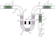
请参照图2,为本发明第一实施例提供的无运动部件的冷热电联供系统100,包括一个热声发动机核心单元1、一个热磁发电单元2和一个热声制冷机核心单元3;所述热声发动机核心单元1包括具有第一端141及第二端142的U形的谐振管14、自第一端141向第二端142依次设置于所述谐振管14第一端内的第一高温端换热器11、发动机回热器12、第一室温端换热器13;所述谐振管14还包括连接于第一端141及第二端142之间的U形部143,所述热磁发电单元2串接于热声发动机核心单元1的谐振管14的U形部143上;所述热声制冷机核心单元3串接于所述谐振管14第二端142上,并且包括自第一端141向第二端142方向依次设置的第二室温端换热器31、制冷机回热器32以及低温端换热器33。Please refer to FIG. 2 , the cogeneration system 100 without moving parts provided for the first embodiment of the present invention includes a thermoacoustic engine core unit 1 , a thermomagnetic power generation unit 2 and a thermoacoustic refrigerator core unit 3 The thermoacoustic engine core unit 1 includes a
请同时参阅图3,所述热磁发电单元2包括自第一端141向第二端142方向依次设置在谐振管14的U形部143内的第三室温端换热器21a、第一热磁材料模块22a、第二高温端换热器24、与第一热磁材料模块22a相对的第二热磁材料模块22b以及与第三室温端换热器21a相对的第四室温端换热器21b;所述热磁发电单元2还包括位于所述谐振管14外的第一永磁体23a、第二永磁体23b、第一线圈25a、第二线圈25b、第一导磁体26a以及第二导磁体26b;所述第一热磁材料模块22a和第二热磁材料模块22b布置在第一导磁体26a和第二导磁体26b之间;所述第一热磁材料模块22a和第二热磁材料模块22b各自的两端分别与所述第一导磁体26a和第二导磁体26b连接;在所述第一热磁材料模块22a和第二热磁材料模块22b之间对称布置有第一永磁体23a和第二永磁体23b;所述第一永磁体23a和第二永磁体23b各自的两端分别与所述第一导磁体26a和第二导磁体26b连接,所述第一永磁体23a的磁北极方向和所述第二永磁体23b的磁北极方向一致;第一线圈25a围绕于所述第一永磁体23a和第二永磁体23b之间的一段第一导磁体26a外;第二线圈25b围绕所述第一永磁体23a和第二永磁体23b之间的一段第二导磁体26b外。Please refer to FIG. 3 at the same time. The thermomagnetic power generation unit 2 includes a third room temperature
在本实施方式中,所述谐振管14的第一端141及第二端142内充注有气体工质,所气体工质选自氮气、氦气、二氧化碳、氩气中的一种或其组合;所述U形部充注有液体工质;所述液体工质优选水、导热油或液态金属。在本实施方式中,所述第一端141及第二端水平对齐设置。In this embodiment, the
在本实施方式中,所述热声发动机核心单元1可以为驻波热声发动机或行波热声发动机或行波/驻波混合型热声发动机或双作用行波热声发动机等。In this embodiment, the thermoacoustic engine core unit 1 may be a standing wave thermoacoustic engine, a traveling wave thermoacoustic engine, a traveling wave/standing wave hybrid thermoacoustic engine, or a double-acting traveling wave thermoacoustic engine.
本实施方式中,所述的第一热磁材料模块22a和第二热磁材料模块22b分别由若干热磁材料片平行叠摞而成。所述第一导磁体26a和第二导磁体26b为由磁通传导材料制成的连接元件,如硅钢片。所述的第一热磁材料模块22a、第一导磁体26a、第一永磁体23a、第二永磁体23b、第二热磁材料模块22b、第二导磁体26b构成磁回路。根据热磁现象,当热磁材料温度在居里温度之下时,热磁材料片呈现磁导率很大的铁磁性,此时所述磁回路中的磁阻减小,环绕磁回路上的第一线圈25a和第二线圈25b中的磁通量增加;当热磁材料片温度在居里温度之上时,热磁材料片呈现磁导率很小的顺磁性,此时所述磁回路中的磁阻增大,第一线圈25a和第二线圈25b中的磁通量减少。随着线圈中磁通量发生变化,进而使得线圈感应产生电流。In this embodiment, the first
下面具体说明本第一实施例提供的无运动部件的冷热电联供系统100的工作过程:所述热声发动机核心单元1的第一高温端换热器11吸收外界高温热源热量形成高温端,所述第一室温端换热器11与外界循环冷却水换热形成室温端(循环冷却水温度相应升高),从而在发动机回热器12上建立起温度梯度,当温度梯度超过临界温度梯度时,热声发动机开始工作,气体工质开始自激起振产生往复振荡的压力波动,从而将热能转化为声功(声波形式的机械能)。往复振荡的压力波动驱动U形的谐振管14中的液体工质往复运动,从而一部分声功被消耗。The working process of the cogeneration system 100 without moving parts provided by the first embodiment is described in detail below: the first high-temperature
所述热磁发电单元2的第二高温端换热器24吸收外界高温热源热量形成高温端,所述第三室温端换热器21a和所述第四室温端换热器21b与外界循环冷却水换热形成室温端(循环冷却水温度相应升高)。当U形谐振管14中的液体工质从右往左运动时,所述第一热磁材料模块22a被加热、第二热磁材料模块22b被冷却,第一热磁材料模块22a的热磁材料呈顺磁态,第二热磁材料模块22b的热磁材料呈铁磁态,则绝大部分磁感应线会从所述第二永磁体23a和第二永磁体23b的磁北极出发,通过第二热磁材料模块22b回到所述第二永磁体23a和第二永磁体23b的磁南极;当U形谐振管14中的液体工质从左往右运动时,所述第一热磁材料模块22a被冷却、第二热磁材料模块22b被加热,第一热磁材料模块22a的热磁材料呈铁磁态,第二热磁材料模块22b的热磁材料呈顺磁态,则绝大部分磁感应线会从所述第二永磁体23a和第二永磁体23b的磁北极出发,通过第一热磁材料模块22a回到所述第二永磁体23a和第二永磁体23b的磁南极。通过交替地加热和冷却第一热磁材料模块22a和第二热磁材料模块22b,第一线圈25a和第二线圈25b中的磁通量在正向的最大值和反向的最大值之间变化,由此可以在线圈中感生出电动势,对外输出电能。The second high-temperature
剩余声功经第二室温端换热器31进入到热声制冷机核心单元3的回热器32中,所述制冷机回热器32通过消耗声功将热量从低温端换热器33泵送到第二室温端换热器31,在制冷机回热器32中形成温度梯度。低温端换热器33与低温热源相连从而降低低温热源的温度,为用户提供制冷量。第二室温端换热器31将来自低温端换热器33的热量释放给流经第二室温端换热器31的冷却水,冷却水温度升高。The remaining sound work enters the
由此,在热声制冷机核心单元3的低温端换热器33处获得制冷量;第一线圈25a第二线圈25b输出电功2输出电功;流出第一室温端换热器11、第二室温端换热器31、第三室温端换热器21a和第四室温端换热器21b的冷却水吸收热量后温度上升,再在所需场合对外供热。Thus, the cooling capacity is obtained at the low-temperature
请参阅图4,为本发明第二实施例提供的无运动部件的冷热电联供系统200,无运动部件的冷热电联供系统200包括两个热声发动机核心单元1、一个热磁发电单元2、一个热声制冷机核心单元3及一个具有第一端141及第二端142的U形的谐振管14;其中一个热声发动机核心单元1包括自第一端141向第二端142依次设置于谐振管14的第一端141内的第一高温端换热器11、发动机回热器12、第一室温端换热器13;另一个热声发动机核心单元1包括自第一端141向第二端142依次设置于谐振管第二端142内的第一室温端换热器13、发动机回热器12及第一高温端换热器11;所述谐振管14还包括连接于第一端及第二端之间的U形部143,所述热磁发电单元2串接于热声发动机核心单元的U形谐振管14的U形部143上;所述热声制冷机核心单元3旁接于U形的谐振管14第二端142上且位于热磁发电单元2与第二端142内的热声发动机核心单元1之间,所述热声制冷机核心单元3包括自靠近谐振管14向远离谐振管14方向依次设置的第二室温端换热器31、制冷机回热器32以及低温端换热器33。本实施方式中,所述热声发动机核心单元1为驻波热声发动机。Please refer to Fig. 4, which is a combined cooling, heating and power system 200 without moving parts provided in the second embodiment of the present invention. The combined cooling, heating and power system 200 without moving parts includes two thermoacoustic engine core units 1, a thermomagnetic Power generation unit 2, a thermoacoustic refrigerator core unit 3 and a U-shaped
请同时参阅图3,本第二实施式的所述热磁发电单元2与第一实施方式的所述热磁发电单元2结构相同,即包括自第一端141向第二端142方向依次设置在谐振管14的U形部内的第三室温端换热器21a、第一热磁材料模块22a、第二高温端换热器24、与第一热磁材料模块22a相对的第二热磁材料模块22b以及与第三室温端换热器21a相对的第四室温端换热器21b;所述热磁发电单元2还包括位于所述谐振管14外的第一永磁体23a、第二永磁体23b、第一线圈25a、第二线圈25b、第一导磁体26a以及第二导磁体26b,在此不再赘述。Please refer to FIG. 3 at the same time. The thermomagnetic power generation unit 2 of the second embodiment has the same structure as the thermomagnetic power generation unit 2 of the first embodiment, that is, it is arranged in sequence from the
在本第二实施方式中,所述热声制冷机核心单元3包括与低温端换热器33连接的脉冲管34、与脉冲管34连接的惯性管35及与惯性管35连接的气库36。为提高热声制冷机核心单元2的制冷性能,采用惯性管35和气库36调节制冷机回热器中32的声场分布。In the second embodiment, the core unit 3 of the thermoacoustic refrigerator includes a
由此,在热声制冷机核心单元3的低温端换热器33处获得制冷量;第一线圈25及第二线圈25b输出电功;流出第一室温端换热器11、第二室温端换热器31、第三室温端换热器21a和第四室温端换热器21b的冷却水吸收热量后温度上升,再在所需场合对外供热。Thus, the cooling capacity is obtained at the low-temperature
请参阅图5,为本发明第三实施例提供的无运动部件的冷热电联供系统300,包括三个热声发动机核心单元1、三个热磁发电单元2和三个热声制冷机核心单元3;每个热声发动机核心单元包括具有第一端141及第二端142的U形的谐振管14、自第一端141向第二端142依次设置于谐振管14第一端141内的第一室温端换热器13、发动机回热器12及第一高温端换热器11;所述谐振管14还包括连接于第一端141及第二端142之间的U形部143,每个热磁发电单元2串接于对应一个热声发动机核心单元1的U形谐振管14的U形部143上;每个热声制冷机核心单元3旁接于对应一个谐振管14第一端141上且位于对应一个热声发动机核心单元1与对应一个热磁发电单元2之间,所述热声制冷机核心单元3包括自靠近谐振管14向远离谐振管14方向依次设置的第二室温端换热器31、制冷机回热器32以及低温端换热器33;三个热声发动机核心单元1的三个谐振管14通过第二端142与第一端141依次首尾串接。本实施方式中,三个热声发动机核心单元1为行波热声发动机单元,即图5中的#1行波热声发动机单元、#2行波热声发动机单元及#3行波热声发动机单元。Please refer to FIG. 5 , a combined cooling, heating and power system 300 without moving parts provided by the third embodiment of the present invention includes three thermoacoustic engine core units 1 , three thermomagnetic power generation units 2 and three thermoacoustic refrigerators Core unit 3; each thermoacoustic engine core unit includes a U-shaped
在本第三实施方式,所述热声制冷机核心单元3包括与低温端换热器33连接的脉冲管34、与脉冲管34连接的惯性管35及与惯性管35连接气库36。为提高热声制冷机核心单元3的制冷性能,采用惯性管35和气库36调节制冷机回热器中32的声场分布。In the third embodiment, the core unit 3 of the thermoacoustic refrigerator includes a
请同时参阅图3,本第三实施式的所述热磁发电单元2与第一及第二实施方式的所述热磁发电单元2结构相同,即包括自第一端141向第二端142方向依次设置在谐振管14的U形部内的第三室温端换热器21a、第一热磁材料模块22a、第二高温端换热器24、与第一热磁材料模块22a相对的第二热磁材料模块22b以及与第三室温端换热器21a相对的第四室温端换热器21b;所述热磁发电单元2还包括位于所述谐振管14外的第一永磁体23a、第二永磁体23b、第一线圈25a、第二线圈25b、第一导磁体26a以及第二导磁体26b,在此不再赘述。Please refer to FIG. 3 at the same time. The thermomagnetic power generation unit 2 of the third embodiment has the same structure as the thermomagnetic power generation unit 2 of the first and second embodiments, that is, it includes the
在本第三实施方式中,每个热声发动机核心单元1还包括与第一高温端换热器11连接的热缓冲管15及与热缓冲管15连接的第五室温段换热器16。In the third embodiment, each thermoacoustic engine core unit 1 further includes a heat buffer pipe 15 connected to the first high
下面具体说明第三实施例提供的无运动部件的冷热电联供系统300的工作过程:#1行波热声发动机单元的第一高温端换热器11吸收外界高温热源热量形成高温端,所述第一室温段换热器13与循环冷却水换热形成室温端,从而在发动机回热器12上形成温度梯度,当发动机回热器12达到一定温度梯度时,系统便自激起振产生往复振荡的压力波动,发动机回热器12在该温度梯度条件下将热能转化成声能(机械能)。声功的传播方向沿着温度梯度的正方向,先传递到热缓冲管15和第五室温端换热器16,一部分声功驱动U形谐振管14中的液体工质往复运动,驱动热磁发电单元2输出电功,余下的声功沿谐振管14传递到下一级行波热声发动机单元(#2)的回热器并被放大。另一部分声功通过连接管道流向热声制冷机核心单元3,从而在热声制冷机核心单元3的低温端换热器33处获得制冷量。The working process of the cogeneration system 300 without moving parts provided by the third embodiment is described in detail below: the first high-temperature
由此,在热声制冷机核心单元3的低温端换热器33处获得制冷量;第一线圈25a第二线圈25b输出电功;流出第一室温端换热器11、第二室温端换热器31、第三室温端换热器21a、第四室温端换热器21b和第五室温端换热器16的冷却水吸收热量后温度上升,再在所需场合对外供热。Thus, the cooling capacity is obtained at the low-temperature
以上所述实施方式仅表达了本发明的一种或几种实施方式,其描述较为具体和详细,但并不能因此而理解为对发明专利范围的限制。应当指出的是,对于本领域的普通技术人员来说,在不脱离本发明构思的前提下,还可以做出多个变形和改进,这些都属于本发明的保护范围。因此,本发明专利的保护范围应以所附权利要求为准。The above-mentioned embodiments only express one or several embodiments of the present invention, and the descriptions thereof are relatively specific and detailed, but should not be construed as limiting the patent scope of the invention. It should be noted that, for those skilled in the art, many modifications and improvements can be made without departing from the concept of the present invention, and these all belong to the protection scope of the present invention. Therefore, the protection scope of the patent for the present invention should be based on the appended claims.
Claims (9)
Priority Applications (1)
| Application Number | Priority Date | Filing Date | Title |
|---|---|---|---|
| CN202010056358.1A CN113137778B (en) | 2020-01-18 | 2020-01-18 | Cogeneration system with no moving parts |
Applications Claiming Priority (1)
| Application Number | Priority Date | Filing Date | Title |
|---|---|---|---|
| CN202010056358.1A CN113137778B (en) | 2020-01-18 | 2020-01-18 | Cogeneration system with no moving parts |
Publications (2)
| Publication Number | Publication Date |
|---|---|
| CN113137778A CN113137778A (en) | 2021-07-20 |
| CN113137778B true CN113137778B (en) | 2023-02-10 |
Family
ID=76808554
Family Applications (1)
| Application Number | Title | Priority Date | Filing Date |
|---|---|---|---|
| CN202010056358.1A Active CN113137778B (en) | 2020-01-18 | 2020-01-18 | Cogeneration system with no moving parts |
Country Status (1)
| Country | Link |
|---|---|
| CN (1) | CN113137778B (en) |
Family Cites Families (7)
| Publication number | Priority date | Publication date | Assignee | Title |
|---|---|---|---|---|
| CN102331109B (en) * | 2011-10-08 | 2013-10-02 | 中科力函(深圳)热声技术有限公司 | Low-temperature thermoacoustic refrigerator |
| JP5970737B2 (en) * | 2011-12-05 | 2016-08-17 | 学校法人東海大学 | Thermoacoustic engine |
| CN104124334A (en) * | 2013-04-27 | 2014-10-29 | 中国科学院理化技术研究所 | Thermo-magnetic power generation system driven by thermo-acoustic engine |
| JP2014217250A (en) * | 2013-04-30 | 2014-11-17 | ローム株式会社 | Thermoelectric generator and thermoelectric power generation system |
| CN103835903B (en) * | 2014-03-14 | 2016-06-15 | 中国科学院理化技术研究所 | Traveling wave thermoacoustic combined cooling heating and power system |
| CN106286004B (en) * | 2016-09-29 | 2018-06-22 | 佛山市程显科技有限公司 | Thermo-acoustic driven multiphase alternating current thermomagnetic power generation system |
| CN110701822B (en) * | 2019-10-17 | 2021-04-20 | 中国科学院理化技术研究所 | A thermal energy-driven thermoacoustic and electric card coupling refrigeration system |
-
2020
- 2020-01-18 CN CN202010056358.1A patent/CN113137778B/en active Active
Also Published As
| Publication number | Publication date |
|---|---|
| CN113137778A (en) | 2021-07-20 |
Similar Documents
| Publication | Publication Date | Title |
|---|---|---|
| CN103835903B (en) | Traveling wave thermoacoustic combined cooling heating and power system | |
| US9777951B2 (en) | Thermoacoustic engine | |
| CN103352817B (en) | Linear type double-acting thermoacoustic power generation system | |
| CN103758657B (en) | Acoustic resonance type traveling wave thermoacoustic power generation system | |
| CN107401852B (en) | Solid state refrigerator with thermoacoustic drive | |
| CN101275541A (en) | Thermoacoustic traveling wave engine and its application | |
| CN104124334A (en) | Thermo-magnetic power generation system driven by thermo-acoustic engine | |
| CN205825484U (en) | Combined cooling and power generation system | |
| CN108167147A (en) | Cascade combined cooling heating and power device | |
| CN105805974B (en) | Combined cooling and power generation system | |
| CN109974324B (en) | Thermo-acoustic loop system capable of being used as power generation, refrigeration or heat pump | |
| CN111256387B (en) | Combined cooling, heating and power system based on thermoacoustic effect and pyroelectric effect | |
| CN103670975B (en) | Thermo-acoustic power generation system simultaneously utilizing cold source and heat source | |
| CN110206657B (en) | A thermal hysteresis free-piston Stirling generator | |
| CN102403447B (en) | Thermo-acoustic driven thermomagnetic power generation system | |
| CN113137778B (en) | Cogeneration system with no moving parts | |
| CN114649921B (en) | An inductive thermoacoustic liquid metal magnetic fluid power generation method | |
| CN113137779B (en) | Combined cooling heating and power system without moving parts | |
| CN111271189B (en) | Combined cooling heating and power system based on thermoacoustic effect and positive and negative electrocaloric effect | |
| CN204552980U (en) | A kind of VM circulating heat pump electricity generating device | |
| CN110971143B (en) | Static thermomagnetic power generation device capable of realizing heat regeneration | |
| CN106286004B (en) | Thermo-acoustic driven multiphase alternating current thermomagnetic power generation system | |
| CN215213715U (en) | A Dual Opposite Electric Feedback Free Piston Stirling Generator | |
| CN216977225U (en) | Loop multi-stage thermally driven heat pump | |
| CN116398318A (en) | Free-piston Stirling power generation system with built-in compressor |
Legal Events
| Date | Code | Title | Description |
|---|---|---|---|
| PB01 | Publication | ||
| PB01 | Publication | ||
| SE01 | Entry into force of request for substantive examination | ||
| SE01 | Entry into force of request for substantive examination | ||
| GR01 | Patent grant | ||
| GR01 | Patent grant |