CN112919460B - Self-supporting porous carbon electrode material - Google Patents
Self-supporting porous carbon electrode material Download PDFInfo
- Publication number
- CN112919460B CN112919460B CN202110123943.3A CN202110123943A CN112919460B CN 112919460 B CN112919460 B CN 112919460B CN 202110123943 A CN202110123943 A CN 202110123943A CN 112919460 B CN112919460 B CN 112919460B
- Authority
- CN
- China
- Prior art keywords
- reactant
- electrode
- temperature
- carbon electrode
- electrode material
- Prior art date
- Legal status (The legal status is an assumption and is not a legal conclusion. Google has not performed a legal analysis and makes no representation as to the accuracy of the status listed.)
- Active
Links
Images


Classifications
-
- C—CHEMISTRY; METALLURGY
- C01—INORGANIC CHEMISTRY
- C01B—NON-METALLIC ELEMENTS; COMPOUNDS THEREOF; METALLOIDS OR COMPOUNDS THEREOF NOT COVERED BY SUBCLASS C01C
- C01B32/00—Carbon; Compounds thereof
- C01B32/30—Active carbon
- C01B32/312—Preparation
-
- H—ELECTRICITY
- H01—ELECTRIC ELEMENTS
- H01G—CAPACITORS; CAPACITORS, RECTIFIERS, DETECTORS, SWITCHING DEVICES, LIGHT-SENSITIVE OR TEMPERATURE-SENSITIVE DEVICES OF THE ELECTROLYTIC TYPE
- H01G11/00—Hybrid capacitors, i.e. capacitors having different positive and negative electrodes; Electric double-layer [EDL] capacitors; Processes for the manufacture thereof or of parts thereof
- H01G11/22—Electrodes
- H01G11/30—Electrodes characterised by their material
- H01G11/32—Carbon-based
- H01G11/34—Carbon-based characterised by carbonisation or activation of carbon
-
- H—ELECTRICITY
- H01—ELECTRIC ELEMENTS
- H01G—CAPACITORS; CAPACITORS, RECTIFIERS, DETECTORS, SWITCHING DEVICES, LIGHT-SENSITIVE OR TEMPERATURE-SENSITIVE DEVICES OF THE ELECTROLYTIC TYPE
- H01G11/00—Hybrid capacitors, i.e. capacitors having different positive and negative electrodes; Electric double-layer [EDL] capacitors; Processes for the manufacture thereof or of parts thereof
- H01G11/84—Processes for the manufacture of hybrid or EDL capacitors, or components thereof
- H01G11/86—Processes for the manufacture of hybrid or EDL capacitors, or components thereof specially adapted for electrodes
-
- H—ELECTRICITY
- H01—ELECTRIC ELEMENTS
- H01M—PROCESSES OR MEANS, e.g. BATTERIES, FOR THE DIRECT CONVERSION OF CHEMICAL ENERGY INTO ELECTRICAL ENERGY
- H01M4/00—Electrodes
- H01M4/02—Electrodes composed of, or comprising, active material
- H01M4/36—Selection of substances as active materials, active masses, active liquids
- H01M4/58—Selection of substances as active materials, active masses, active liquids of inorganic compounds other than oxides or hydroxides, e.g. sulfides, selenides, tellurides, halogenides or LiCoFy; of polyanionic structures, e.g. phosphates, silicates or borates
- H01M4/583—Carbonaceous material, e.g. graphite-intercalation compounds or CFx
-
- Y—GENERAL TAGGING OF NEW TECHNOLOGICAL DEVELOPMENTS; GENERAL TAGGING OF CROSS-SECTIONAL TECHNOLOGIES SPANNING OVER SEVERAL SECTIONS OF THE IPC; TECHNICAL SUBJECTS COVERED BY FORMER USPC CROSS-REFERENCE ART COLLECTIONS [XRACs] AND DIGESTS
- Y02—TECHNOLOGIES OR APPLICATIONS FOR MITIGATION OR ADAPTATION AGAINST CLIMATE CHANGE
- Y02E—REDUCTION OF GREENHOUSE GAS [GHG] EMISSIONS, RELATED TO ENERGY GENERATION, TRANSMISSION OR DISTRIBUTION
- Y02E60/00—Enabling technologies; Technologies with a potential or indirect contribution to GHG emissions mitigation
- Y02E60/10—Energy storage using batteries
Landscapes
- Engineering & Computer Science (AREA)
- Chemical & Material Sciences (AREA)
- Power Engineering (AREA)
- Microelectronics & Electronic Packaging (AREA)
- Organic Chemistry (AREA)
- Inorganic Chemistry (AREA)
- Electrochemistry (AREA)
- General Chemical & Material Sciences (AREA)
- Chemical Kinetics & Catalysis (AREA)
- Manufacturing & Machinery (AREA)
- Materials Engineering (AREA)
- Carbon And Carbon Compounds (AREA)
- Electric Double-Layer Capacitors Or The Like (AREA)
Abstract
自支撑多孔碳电极材料,其制备方法包括:将柠檬酸、尿素以及乙二醇为代表的反应物在中性酸碱度条件下进行恒温溶胶凝胶反应生成胶状前驱体,之后在惰性气氛保护下对胶状前驱体进行热解处理得到多孔碳电极材料。本发明能够以简单可控的方法低成本生产高性能氮掺杂多孔碳电极材料。A self-supporting porous carbon electrode material, the preparation method of which includes: reactants represented by citric acid, urea and ethylene glycol are subjected to a constant temperature sol-gel reaction under neutral pH conditions to form a colloidal precursor, and then under the protection of an inert atmosphere The colloidal precursor is pyrolyzed to obtain a porous carbon electrode material. The invention can produce high-performance nitrogen-doped porous carbon electrode materials at low cost through a simple and controllable method.
Description
技术领域technical field
本发明涉及一种自支撑多孔碳电极材料。The invention relates to a self-supporting porous carbon electrode material.
背景技术Background technique
目前,以锂离子电池、钠离子电池、超级电容器和全固态电池等为代表的新能源器件引起广大科研工作者的兴趣。电池的性能与电极材料的物理化学性质息息相关。碳材料由于具备较大的比表面积、良好的导电性和耐酸碱性、资源丰富、成本低等优势,已经成为商业化电极材料。为了提升储能器件的能量密度,提高电极材料的载量和厚度至关重要。传统电极的制备工艺是将碳颗粒、导电颗粒和粘结剂机械混合后刮涂在集流器体。这种制备工艺难以得到高性能的厚电极。主要原因如下:(1)粘结剂是不导电且憎水的,会降低电极的电子和离子的导电性;(2)粘结剂和集流体是电化学惰性的,不会贡献储能容量,而且质量占到了电极了2/3,因此会降低整体电池器件的能量密度;(3)远离集流体的部分活性物质与集流体间的粘结性下降明显,活性物质之间的粘结力不佳,导致高负载电极材料从集流上脱落。At present, new energy devices represented by lithium-ion batteries, sodium-ion batteries, supercapacitors and all-solid-state batteries have aroused the interest of researchers. The performance of batteries is closely related to the physical and chemical properties of electrode materials. Carbon materials have become commercial electrode materials due to their advantages such as large specific surface area, good electrical conductivity, acid and alkali resistance, abundant resources, and low cost. In order to increase the energy density of energy storage devices, it is very important to increase the loading and thickness of electrode materials. The traditional electrode preparation process is to mechanically mix carbon particles, conductive particles and binders and then scrape-coat them on the current collector body. This preparation process is difficult to obtain high-performance thick electrodes. The main reasons are as follows: (1) The binder is non-conductive and hydrophobic, which will reduce the electronic and ionic conductivity of the electrode; (2) The binder and current collector are electrochemically inert and will not contribute to the energy storage capacity. , and the mass accounts for 2/3 of the electrode, so the energy density of the overall battery device will be reduced; (3) the adhesion between the part of the active material far away from the current collector and the current collector decreases significantly, and the adhesion between the active materials Poor, causing highly loaded electrode material to come off the current collector.
为避免上述问题,还出现了以下各种自支撑、无需粘结剂的高负载碳材料电极。1、利用木材等具备一定力学强度的天然材料作为前驱体经过一步碳化、活化得到自支撑多孔碳;但是这些天然多孔物质的组分、孔结构已经较为固定,进一步的调控难度比较大。2、利用低维度的材料组装成自支撑三维多孔碳,比如冰模法、静电组装、真空抽滤、静电纺丝等;但是这些方法工艺较为复杂、需要特殊的工艺设备、产率不高。3、利用多孔金属泡沫作为载体经化学气相沉积构建自支撑碳电极;但是该方法能耗大、制备过程复杂、生产成本高等影响其实际应用。4、利用Pd/Cu催化交联有机高聚物衍生的微孔丰富的多孔碳,但这需要用到昂贵金属催化剂和有毒的四氢呋喃溶剂。5、相分离制备的多孔聚合物经过碳化也能得到自支撑的多孔碳电极,比如利用两性聚离子液体通过组装形成超分子交联前驱体,经相分离、碳化得到了多孔碳膜;但其制备过程比较复杂,溶剂置换过程要消耗大量的有机溶剂。To avoid the above-mentioned problems, the following self-supporting, binder-free highly loaded carbon material electrodes have also emerged. 1. Use wood and other natural materials with certain mechanical strength as precursors to obtain self-supporting porous carbon through one-step carbonization and activation; however, the components and pore structures of these natural porous materials are relatively fixed, and further regulation is relatively difficult. 2. Use low-dimensional materials to assemble self-supporting three-dimensional porous carbon, such as ice mold method, electrostatic assembly, vacuum filtration, electrospinning, etc.; but these methods are relatively complicated, require special process equipment, and the yield is not high. 3. Using porous metal foam as a carrier to construct a self-supporting carbon electrode by chemical vapor deposition; however, this method has high energy consumption, complicated preparation process, and high production cost, which affect its practical application. 4. Using Pd/Cu to catalyze the cross-linking of organic polymer-derived porous carbon with rich micropores, but this requires the use of expensive metal catalysts and toxic tetrahydrofuran solvents. 5. Porous polymers prepared by phase separation can also obtain self-supporting porous carbon electrodes after carbonization. For example, amphoteric polyionic liquids are used to form supramolecular crosslinking precursors through assembly, and porous carbon films are obtained through phase separation and carbonization; but other The preparation process is relatively complicated, and a large amount of organic solvent is consumed in the solvent replacement process.
发明内容Contents of the invention
本发明的目的是提供一种多孔碳电极材料,其能避免或改善背景技术部分所提及的相关缺陷。The purpose of the present invention is to provide a porous carbon electrode material, which can avoid or improve the related defects mentioned in the background art section.
根据本发明的第一方面,提供了一种碳电极材料制备方法,其包括:According to a first aspect of the present invention, a method for preparing a carbon electrode material is provided, comprising:
提供含羧基的第一反应物,其中第一反应物选自柠檬酸、海藻酸钠、羧甲基纤维素、羧甲基甲壳素、羧甲基壳聚糖、蛋白质和腐植酸中的至少一种;Provide carboxyl-containing first reactant, wherein the first reactant is selected from at least one of citric acid, sodium alginate, carboxymethyl cellulose, carboxymethyl chitin, carboxymethyl chitosan, protein and humic acid kind;
提供含羟基的第二反应物,其中第二反应物选自乙二醇、乙醇、甲醇、间苯二酚、苯酚、丙醇和丙三醇中的至少一种;providing a hydroxyl-containing second reactant, wherein the second reactant is selected from at least one of ethylene glycol, ethanol, methanol, resorcinol, phenol, propanol and glycerol;
提供含氨基的第三反应物,其中第三反应物选自尿素、三聚氰胺、二乙醇胺、聚乙烯胺、聚丙烯酰胺、壳聚糖中的至少一种;A third reactant containing an amino group is provided, wherein the third reactant is selected from at least one of urea, melamine, diethanolamine, polyvinylamine, polyacrylamide, and chitosan;
将第一反应物和第三反应物加水溶解后与第二反应物混合形成反应溶液,其中第一反应物与第三反应物的质量比为:(4:1)~(1:2),第一反应物与第二反应物的质量比为:(2:1)~(1:4);The first reactant and the third reactant are dissolved in water and mixed with the second reactant to form a reaction solution, wherein the mass ratio of the first reactant to the third reactant is: (4:1)~(1:2), The mass ratio of the first reactant to the second reactant is: (2:1)~(1:4);
将反应溶液pH值调节为7左右;Adjust the pH value of the reaction solution to about 7;
将反应溶液在80~140℃下反应5~10小时,直至生成胶状前驱体;以及reacting the reaction solution at 80-140° C. for 5-10 hours until a colloidal precursor is produced; and
惰性气氛保护下对胶状前驱体进行热解处理以得到多孔碳电极材料,其中热解处理过程的升温速率在5℃/min以下,升至600~1300℃的热解温度后恒温0.5~4h。Under the protection of an inert atmosphere, the colloidal precursor is pyrolyzed to obtain a porous carbon electrode material, wherein the heating rate of the pyrolysis process is below 5°C/min, and the pyrolysis temperature is raised to 600-1300°C and then kept at a constant temperature for 0.5-4h .
根据本发明的一个优选实施方式,第一反应物为柠檬酸、第二反应物为乙二醇并且第三反应物为尿素,三者的质量比大致为1:1:1。According to a preferred embodiment of the present invention, the first reactant is citric acid, the second reactant is ethylene glycol, and the third reactant is urea, and the mass ratio of the three is approximately 1:1:1.
根据本发明的另一个优选实施方式,反应温度为130℃左右,反应时间为7h左右。According to another preferred embodiment of the present invention, the reaction temperature is about 130° C., and the reaction time is about 7 hours.
根据本发明的另一个优选实施方式,热解升温速率为2℃/min左右,热解温度为800℃左右,恒温热解时间为2h左右。According to another preferred embodiment of the present invention, the pyrolysis heating rate is about 2°C/min, the pyrolysis temperature is about 800°C, and the constant temperature pyrolysis time is about 2h.
根据本发明的又一个优选实施方式,还可以包括对所制得的碳电极材料进一步进行物理或化学活化造孔。According to yet another preferred embodiment of the present invention, further physical or chemical activation of pore formation to the prepared carbon electrode material may also be included.
本发明的惰性气氛可以采用氮气或氩气等。The inert atmosphere of the present invention can adopt nitrogen or argon etc.
根据本发明的第二方面,还提供了一种电极,由根据上述方法所制备的碳电极材料形成。According to the second aspect of the present invention, an electrode is also provided, which is formed from the carbon electrode material prepared according to the above method.
根据本发明,由上述碳电极材料形成所需尺寸的电极之后,进一步对电极进行活化造孔。优选在保护气氛下通过热处理进行活化造孔。保护气氛优选采用二氧化碳气体,热处理温度优选为700℃至900℃,更优选为800℃左右。时间优选为10小时以下,更优选为7-9小时。通过控制包括温度和时间在内的热处理活化造孔手段,不但可以优化孔隙度,还可以同时调控碳电极的氮含量在理想范围之内,并能够保障碳电极自身的支撑强度(自支撑物理性能)。According to the present invention, after forming an electrode with a required size from the above-mentioned carbon electrode material, the electrode is further activated to form pores. The activation pore creation is preferably carried out by heat treatment under protective atmosphere. The protective atmosphere is preferably carbon dioxide gas, and the heat treatment temperature is preferably 700°C to 900°C, more preferably around 800°C. The time is preferably less than 10 hours, more preferably 7-9 hours. By controlling the heat treatment activation method including temperature and time, not only the porosity can be optimized, but also the nitrogen content of the carbon electrode can be adjusted within the ideal range, and the support strength of the carbon electrode itself can be guaranteed (self-supporting physical properties ).
根据本发明的其它方面,还提供了具有上述电极的电容或电池。According to other aspects of the present invention, a capacitor or battery having the above-mentioned electrodes is also provided.
本发明至少具有如下优点:The present invention has following advantage at least:
1、本发明得到的自支撑碳电极,能够避免使用不导电粘结剂,因此电极材料本身的导电性得到提升。另外,还同时避免了质量较重的集流体的使用,不存在电极材料与集流体间的接触电阻,从而整体提升了电极的电子传输效率。此外,这些非活性物质质量和体积的减少,不仅降低成本支出,还能够让单位面积或单位体积内的活性物质量增加,对于电池整体能量密度提升非常有利。1. The self-supporting carbon electrode obtained in the present invention can avoid the use of a non-conductive binder, so the conductivity of the electrode material itself is improved. In addition, the use of a heavy current collector is avoided at the same time, and there is no contact resistance between the electrode material and the current collector, thereby improving the electron transmission efficiency of the electrode as a whole. In addition, the reduction in the mass and volume of these inactive materials not only reduces the cost, but also increases the amount of active materials per unit area or unit volume, which is very beneficial to the improvement of the overall energy density of the battery.
2、传统颗粒碳电极在长期电池充放电过程中,粘结剂强度逐渐减弱,颗粒间粘结性受到影响,使得活性物质容易剥离、脱落和开裂,降低了电极的稳定性和电池的寿命。而本发明的自支撑碳电极,具有良好的力学稳定性,自成一体碳骨架,有助于电池循环稳定性的提高。2. During the long-term charging and discharging process of the traditional granular carbon electrode, the strength of the binder gradually weakens, and the adhesion between the particles is affected, which makes the active material easy to peel off, fall off and crack, reducing the stability of the electrode and the life of the battery. However, the self-supporting carbon electrode of the present invention has good mechanical stability and a self-contained carbon skeleton, which contributes to the improvement of battery cycle stability.
3、本发明能够以简单可控的低成本方法生产电极材料。3. The present invention can produce electrode materials in a simple, controllable and low-cost method.
4、本发明可以灵活实现碳材料的多组分调控。另外,本发明的分子交联形成网络结构这种策略,使其能够与造孔的模板结合,比如常见的二氧化硅硬模板法、盐模板化和软模板法等,通过分子交联的前驱体将这些模板分子均匀包在内部,经碳化后续处理,便可以对碳材料本身孔结构进行调控,从而还便于孔结构的进一步后续优化。4. The present invention can flexibly realize multi-component regulation of carbon materials. In addition, the molecular cross-linking strategy of the present invention to form a network structure enables it to be combined with pore-forming templates, such as the common silica hard template method, salt templating and soft template methods, etc., through molecular cross-linking precursors These template molecules are uniformly wrapped in the body, and after carbonization subsequent treatment, the pore structure of the carbon material itself can be regulated, which is also convenient for further subsequent optimization of the pore structure.
5、本发明还可以调节或丰富氮元素掺杂量。氮掺的多孔碳在电化学多种应用中有良好的效果,比如电催化、赝电容器、提升钠离子电池容量等等。因此,本发明还可以通过可控调节来获得丰富合适的氮掺杂量,从而能够提升碳材料的导电性和亲水性,并因此提升碳电极性能。5. The present invention can also adjust or enrich the doping amount of nitrogen element. Nitrogen-doped porous carbons have shown promising results in various electrochemical applications, such as electrocatalysis, pseudocapacitors, and capacity enhancement of Na-ion batteries, among others. Therefore, the present invention can also obtain a rich and suitable nitrogen doping amount through controllable adjustment, so as to improve the conductivity and hydrophilicity of the carbon material, and thus improve the performance of the carbon electrode.
附图说明Description of drawings
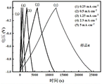
图1是根据本发明最佳测试例所组装的电容器在不同电流密度下的充放电曲线;Fig. 1 is the charge-discharge curve of the assembled capacitor according to the best test example of the present invention under different current densities;
图2是根据本发明最佳测试例所组装的电容器与根据对比例所组装的电容器在电流密度为10mAcm-2时的充放电曲线。Fig. 2 is the charging and discharging curves of the capacitor assembled according to the best test example of the present invention and the capacitor assembled according to the comparative example when the current density is 10mAcm -2 .
图3是根据本发明最佳测试例所组装的电容器与根据对比例所组装的电容器在不同电流密度下的面积比电容值。Fig. 3 is the area specific capacitance values of the capacitor assembled according to the best test example of the present invention and the capacitor assembled according to the comparative example at different current densities.
具体实施方式Detailed ways
以下结合附图,通过具体实例详细说明本发明。The present invention will be described in detail through specific examples below in conjunction with the accompanying drawings.
实施例:制备自支撑多孔碳电极材料Example: Preparation of self-supporting porous carbon electrode material
步骤(1):称取20g柠檬酸,20g尿素,常温下溶于35mL的去离子水中,再加入25mL的乙二醇,磁力搅拌5h,溶液当中加入一定量氨水,调整pH到中性。Step (1): Weigh 20g of citric acid and 20g of urea, dissolve them in 35mL of deionized water at room temperature, then add 25mL of ethylene glycol, stir magnetically for 5 hours, add a certain amount of ammonia water to the solution, and adjust the pH to neutral.
步骤(2):将上述混合液体置在油浴锅当中,升温到130℃加热7h,将液体中的水分蒸干的同时,让材料在高温下发生交联过程,得到粘稠性胶状液。Step (2): Put the above mixed liquid in an oil bath, heat it up to 130°C for 7 hours, evaporate the water in the liquid, and let the material undergo a crosslinking process at high temperature to obtain a viscous colloidal liquid .
步骤(3):将上述胶状液马上转入瓷舟,并转移到气氛管式炉中,在N2的惰性气体下高温碳化2h。温度设定在800℃,升温速率为2℃/min。Step (3): Immediately transfer the above colloidal liquid into a porcelain boat, and transfer it to an atmosphere tube furnace, and carbonize it at a high temperature for 2 hours under an inert gas of N 2 . The temperature was set at 800°C, and the heating rate was 2°C/min.
测试例:将上述实施例制得的材料形成电极后组装成电容器Test example: the materials prepared in the above examples are formed into electrodes and then assembled into capacitors
步骤(1):将上述实施例得到的碳块进行打磨至700μm,并用乙醇和水反复超声清洗,确保电极表面没有杂质,然后烘干备用。Step (1): Grind the carbon block obtained in the above example to 700 μm, and repeatedly ultrasonically clean it with ethanol and water to ensure that there is no impurity on the surface of the electrode, and then dry it for later use.
步骤(2):将步骤(1)得到的碳电极放入管式炉中,CO2气氛下800℃进行活化热处理。Step (2): put the carbon electrode obtained in step (1) into a tube furnace, and perform activation heat treatment at 800°C under a CO 2 atmosphere.
步骤(3):将活化后得到的碳电极直接作为工作电极,铂片作为对电极,Hg/HgO作为参比电极,1.0M H2SO4作为电解液,先在三电极体系下测试电容行为。Step (3): The carbon electrode obtained after activation is directly used as the working electrode, the platinum sheet is used as the counter electrode, Hg/HgO is used as the reference electrode, and 1.0MH 2 SO 4 is used as the electrolyte, and the capacitance behavior is first tested in the three-electrode system.
步骤(4):在正式测试之前,静置12h,让电极与电解液有充分的浸入时间。Step (4): Before the official test, let it stand for 12 hours to allow the electrodes and electrolyte to have sufficient immersion time.
步骤(5):结合循环伏安、恒电流充放电、电化学阻抗谱等进行性能测试。Step (5): Perform performance tests in combination with cyclic voltammetry, galvanostatic charge and discharge, and electrochemical impedance spectroscopy.
上述步骤(2)中,活化热处理时间采用变量,分别为0、3、6、9及12小时,其中活化热处理时间为0、3、6、9小时所对应组装的电容器分别为样品1,样品2,样品3,样品4,其性能测试结果参见表1及图1;而由于活化热处理12小时所得电极由于自身强度原因已经无法用作自支撑电极,故而没有对应组装的电容器。In the above step (2), the activation heat treatment time adopts variables, which are 0, 3, 6, 9 and 12 hours respectively, and the capacitors assembled corresponding to the activation heat treatment time of 0, 3, 6, and 9 hours are
表1Table 1
如表1所示,同样在0.5mA cm-2电流密度下,样品4的电容器的面积比电容高达3125mF cm-2,比表面积高达624.6m2g-1,同时电极材料中的氮含量仍有7.01%。合适的氮掺杂有利于电极材料导电性和润湿性的提升,并因此有助于良好的电容行为。如图1所示,样品4的电容器的充放电曲线还表现出最大充放电时间,并因此具有最佳电池性能,这与其拥有最大的比表面积和合适的氮掺杂水平等密切相关。As shown in Table 1, at the same current density of 0.5mA cm -2 , the area specific capacitance of the capacitor of
图1是根据本发明最佳测试例样品4所组装的电容器在不同电流密度下的充放电曲线;图3是其在不同电流密度下的电容值。如图1和图3所示,图1显示的充放电曲线呈对称三角形,说明其拥有良好的电容响应,图3显示的电容值说明电极展现出良好的倍率性能,尤其在10mA cm-2电流密度下达到了2380mF cm-2比容量,电流密度从0.25增大到10mA cm-2条件下比电容保持率为73.2%。Fig. 1 is the charging and discharging curves of the assembled capacitor according to the best
对比例:采用传统材料形成电极后组装成电容器Comparative example: using traditional materials to form electrodes and assemble them into capacitors
将商用活性炭(日本可乐丽活性炭,YP-50F)、导电炭黑、粘结剂按质量比为8:1:1混合、研磨、制成浆料,并刮涂到集流体泡沫镍上,刮涂的厚度与上述测试例保持一致,均为700μm。将制备的电极真空干燥24h备用。后续的测试步骤与测试例的步骤(3)~(5)一致。Mix commercial activated carbon (Japan Kuraray activated carbon, YP-50F), conductive carbon black, and binder in a mass ratio of 8:1:1, grind, make a slurry, and scrape coat it on the nickel foam of the current collector, scrape The thickness of the coating is consistent with the above test example, which is 700 μm. The prepared electrode was vacuum dried for 24 h for use. Subsequent test steps are consistent with steps (3)-(5) of the test case.
表2给出了根据对比例组装的电容器与本发明测试例中样品4的电容器在不同电流密度下的电容性能比对。Table 2 shows the comparison of the capacitance performance of the capacitor assembled according to the comparative example and the capacitor of
表2Table 2

如表2所示,与同样厚度的商用活性炭制备的厚电极相比,根据本发明的测试例样品4表现出更佳的电容性能。尤其是倍率性能,活性炭电极在10mA cm-2的电流密度下只有673mF cm-2,电流密度从0.25增大到10mA cm-2条件下比电容保持率只有22.9%。这是因为传统的活性炭电极的孔结构单一,不利于电解液的传输,当电极尺寸变厚时,进一步阻碍了物质扩散效率,因此大电流工作时极化严重。同时,还需要用到不导电的粘结剂,也是导致电容性能下降原因。As shown in Table 2, compared with the thick electrode prepared by commercial activated carbon with the same thickness, the
图2是根据本发明最佳测试例样品4所组装的电容器与根据对比例所组装的电容器在电流密度为10mA cm-2时的充放电曲线。本发明的测试例样品4的电容器的充放电曲线表现出其在同样电流密度下具有明显更长的充放电时间。图3所示是本发明测试例样品4与对比例活性炭所组装电容器在不同电流密度下的电容值,随着电流密度增大,本发明样品4的电容器的比电容下降较慢,而对比例活性炭电容器的性能下降明显,再次证明本发明中样品4的电容器具有更优异的倍率性能。Fig. 2 is the charging and discharging curves of the capacitor assembled according to the best
Claims (3)
Priority Applications (1)
| Application Number | Priority Date | Filing Date | Title |
|---|---|---|---|
| CN202110123943.3A CN112919460B (en) | 2021-01-29 | 2021-01-29 | Self-supporting porous carbon electrode material |
Applications Claiming Priority (1)
| Application Number | Priority Date | Filing Date | Title |
|---|---|---|---|
| CN202110123943.3A CN112919460B (en) | 2021-01-29 | 2021-01-29 | Self-supporting porous carbon electrode material |
Publications (2)
| Publication Number | Publication Date |
|---|---|
| CN112919460A CN112919460A (en) | 2021-06-08 |
| CN112919460B true CN112919460B (en) | 2022-12-02 |
Family
ID=76168364
Family Applications (1)
| Application Number | Title | Priority Date | Filing Date |
|---|---|---|---|
| CN202110123943.3A Active CN112919460B (en) | 2021-01-29 | 2021-01-29 | Self-supporting porous carbon electrode material |
Country Status (1)
| Country | Link |
|---|---|
| CN (1) | CN112919460B (en) |
Family Cites Families (6)
| Publication number | Priority date | Publication date | Assignee | Title |
|---|---|---|---|---|
| US10590277B2 (en) * | 2014-03-14 | 2020-03-17 | Group14 Technologies, Inc. | Methods for sol-gel polymerization in absence of solvent and creation of tunable carbon structure from same |
| FR3050208B1 (en) * | 2016-04-18 | 2018-04-27 | Hutchinson | MICROPOROUS CARBON OF HIGH DENSITY AND PROCESS FOR PREPARING THE SAME |
| CN109637829B (en) * | 2018-12-25 | 2020-07-07 | 福州大学 | A method for preparing nitrogen-doped porous carbon by cross-linking sodium alginate and diamine compounds |
| JP7132258B2 (en) * | 2020-02-19 | 2022-09-06 | グループ14・テクノロジーズ・インコーポレイテッド | A novel method for solvent-free sol-gel polymerization and fabrication of variable carbon structures derived from sol-gel polymerization |
| CN111704133B (en) * | 2020-07-09 | 2022-03-11 | 盐城工学院 | Preparation method of self-supporting porous carbon electrode material |
| CN111777055B (en) * | 2020-07-09 | 2023-06-27 | 盐城工学院 | A preparation method of heteroatom-doped porous carbon electrode material |
-
2021
- 2021-01-29 CN CN202110123943.3A patent/CN112919460B/en active Active
Also Published As
| Publication number | Publication date |
|---|---|
| CN112919460A (en) | 2021-06-08 |
Similar Documents
| Publication | Publication Date | Title |
|---|---|---|
| Ruan et al. | Biomass-derived carbon materials for high-performance supercapacitor electrodes | |
| US7419649B2 (en) | Macroreticular carbonaceous material useful in energy storing devices | |
| JP7263397B2 (en) | Method for producing modified graphite-based composite material for long-term cycle and lithium-ion battery containing the material | |
| CN108010747B (en) | Preparation method of nitrogen-sulfur double-doped activated carbon for supercapacitor | |
| CN105671692B (en) | The preparation method for the Nitrogen-rich porous carbon fiber electrode material that melamine resin is modified | |
| CN101306807A (en) | A kind of preparation method of nitrogen-doped porous carbon material | |
| CN108689397A (en) | A kind of carbon hollow ball aeroge, preparation method and application | |
| CN101388291B (en) | Boron-containing porous carbon electrode material and preparation method thereof | |
| CN107400903B (en) | Three-dimensional nano porous copper modified foam nickel and preparation method and application thereof | |
| CN107827107A (en) | A kind of preparation method of the hollow porous charcoal micro-pipe of kapok base or porous charcoal micro-strip | |
| CN108390072A (en) | A kind of cobalt sulfide dopen Nano porous carbon elctro-catalyst and the preparation method and application thereof | |
| CN116154122A (en) | Porous silicon-based anode material, solid electrode and preparation method | |
| Yuan et al. | Highly ordered mesoporous carbon synthesized via in situ template for supercapacitors | |
| CN110880425A (en) | A core-shell nano-needle composite material with stable and controllable morphology and its preparation method and application | |
| CN105140043B (en) | Mn oxide/nitrogen-doped carbon microballoon combination electrode material and its preparation and application | |
| CN113270275B (en) | Metal-organic framework and nanofiber-derived composite electrode and preparation method thereof | |
| CN112919460B (en) | Self-supporting porous carbon electrode material | |
| CN108529588A (en) | The preparation method of ordered mesoporous carbon | |
| CN117865121A (en) | A porous carbon material and its preparation method and application | |
| CN105655153B (en) | Preparation method of self-supporting capacitor electrode material | |
| CN115124020A (en) | A boron-nitrogen co-doped carbon material with hierarchical pores and its preparation method and application | |
| CN119218991B (en) | A porous carbon material with a semi-slope platform pore structure, preparation method and application thereof | |
| CN114899015A (en) | Zinc ion super capacitor positive electrode material and preparation method and application thereof | |
| JP4935374B2 (en) | Electrode material for electric double layer capacitor, method for producing the same, and electric double layer capacitor | |
| CN118629789B (en) | A transition metal oxide/carbon composite microsphere and its preparation method and application |
Legal Events
| Date | Code | Title | Description |
|---|---|---|---|
| PB01 | Publication | ||
| PB01 | Publication | ||
| SE01 | Entry into force of request for substantive examination | ||
| SE01 | Entry into force of request for substantive examination | ||
| GR01 | Patent grant | ||
| GR01 | Patent grant | ||
| OL01 | Intention to license declared | ||
| OL01 | Intention to license declared |