Detailed Description
To facilitate an understanding of the invention, the invention will now be described more fully with reference to the accompanying drawings. Preferred embodiments of the present invention are shown in the drawings. This invention may, however, be embodied in many different forms and should not be construed as limited to the embodiments set forth herein. Rather, these embodiments are provided so that this disclosure will be thorough and complete.
It will be understood that when an element is referred to as being "secured to" another element, it can be directly on the other element or intervening elements may also be present. When an element is referred to as being "connected" to another element, it can be directly connected to the other element or intervening elements may also be present. As used herein, the terms "vertical," "horizontal," "left," "right," "upper," "lower," "front," "rear," "circumferential," and the like are based on the orientation or positional relationship shown in the drawings for ease of description and simplicity of description, and do not indicate or imply that the referenced device or element must have a particular orientation, be constructed and operated in a particular orientation, and are therefore not to be considered limiting of the present invention.
Unless defined otherwise, all technical and scientific terms used herein have the same meaning as commonly understood by one of ordinary skill in the art to which this invention belongs. The terminology used in the description of the invention herein is for the purpose of describing particular embodiments only and is not intended to be limiting of the invention. As used herein, the term "and/or" includes any and all combinations of one or more of the associated listed items.
Newly released technical specifications of electric vehicle remote service and management systems stipulate that new energy vehicle enterprises need to construct monitoring platforms of new energy vehicles, upload electric vehicle data to the monitoring platforms of the enterprises, and forward the electric vehicle data to public platforms. The data uploaded by the electric automobile comprise different operation data such as vehicle running and vehicle charging, a large amount of electric automobile data are accumulated on an enterprise platform and a public platform, but no standard available monitoring method is available for fully utilizing the data so as to realize remote monitoring of the electric automobile. The invention provides a remote monitoring method of a charging device, which can accurately and effectively identify the charging condition of the charging device.
Fig. 1 is a flowchart of a method for remotely monitoring a charging device according to an embodiment of the present invention, where the method for remotely monitoring a charging device includes the following steps S100 to S400.
S100: acquiring charging monitoring data of charging equipment; the charging monitoring data includes a charging state of the charging device.
S200: judging the charging state change condition of the charging equipment according to the charging monitoring data;
s300: marking a charging start bit and a charging end bit according to the charging state change condition, and recording charging monitoring data between the charging start bit and the charging end bit;
s400: and monitoring the charging behavior according to the recorded charging monitoring data between the charging start bit and the charging end bit.
In this embodiment, the charging device is an electric vehicle. The electric vehicle data is transmitted to the enterprise cloud platform by a TBOX (Telematics BOX) of the electric vehicle, and the enterprise cloud platform recognizes the charging behavior and calculates the battery performance index according to the uploaded electric vehicle data. Because the electric vehicle data includes different operation data such as vehicle driving and vehicle charging, data separation needs to be performed on the electric vehicle data to obtain charging monitoring data of the electric vehicle. The charging monitoring data comprises the charging state of the electric automobile. Electric vehicles have multiple states of charge, and therefore, there are transitions between different states of charge.
According to the charging state change condition of the electric automobile in different charging monitoring data, marking a charging start bit and a charging end bit, and recording effective charging monitoring data between the charging start bit and the charging end bit. And selecting a proper flag bit combination based on the charging start bit and the charging end bit, and judging the charging behavior of the electric automobile according to the recorded charging monitoring data.
The method identifies the charging state of the electric vehicle by using the charging monitoring data of the electric vehicle data, and remotely monitors the key performance index of the power battery based on the calculation of the charging section data of the battery vehicle. The monitoring steps of the power battery are simplified, the recognizable working conditions for monitoring the power battery are enlarged, and the cost of manpower and material resources is reduced. The charging state of the electric automobile is identified by the charging start bit and the charging end bit, effective charging behavior is identified, the influence of data loss and poor data quality on an identification result can be avoided, and meanwhile, the remote monitoring efficiency is improved.
In one embodiment, the charging state of the electric vehicle includes non-charging, charging and charging completion, and therefore, the charging state change includes four possible changes, i.e., a change from charging to non-charging, a change from non-charging to charging, a change from charging to charging completion and a change from charging completion to non-charging.
In order to better illustrate the testing steps of the remote monitoring method of the charging device, the present invention is illustrated with a set of actual charging monitoring data, but the present invention is not to be construed as limiting the scope of the invention. Please refer to table 1 for the remote monitoring data of the electric vehicle.
Table 1 remote monitoring data recording table 1 for electric vehicle
In table 1, the 3 rd and 22 th data represent the omission of intermediate charge state duplication. The charge monitoring data includes a state of charge, data acquisition time, a maximum temperature value, SOC, total voltage, cell voltage difference (V), and battery temperature difference (deg.c). In addition, 1 in the charging state represents that charging is in progress, 3 represents that charging is not in progress, the data acquisition time represents the uploading time of the data, and the highest temperature value represents the highest temperature value in the temperature probe in the battery pack at the moment. And when the charging state is identified, judging the charging state change condition according to the charging state change condition in the charging monitoring data.
Fig. 2 is a flowchart of a method for marking a charging start bit and a charging end bit in one embodiment of the present invention, where in one embodiment, the marking a charging start bit and a charging end bit according to the charging state change condition and recording charging monitoring data of the charging start bit and charging monitoring data of the charging end bit includes the following steps S310 to S340.
S310: when the charging state change condition is changed from non-charging to charging, marking the moment as a charging start bit.
S320: when the charging state change condition is that the charging is changed into non-charging or changed from charging into charging completion, marking the moment as a charging end bit.
S330: and when the charging state change condition is changed from charging completion to non-charging, marking is not performed.
S340: charging monitoring data marked as between the charging start bit and the charging end bit is recorded.
When the charging state in the charging monitoring data is changed from non-charging to charging, the power battery is judged to start charging, and the moment of the charging monitoring data at the moment of the change is marked as a charging start bit. When the charging state in the charging monitoring data is changed from charging to non-charging or from charging to charging completion, the moment of the piece of charging monitoring data at the moment of the change is marked as a charging end bit. And when the charging state change condition in the charging monitoring data is changed from charging to non-charging, the data is not marked and recorded. And finally, recording the charging monitoring data marked between the charging start bit and the charging end bit, wherein the charging monitoring data between the charging start bit and the charging end bit is valid data and can be used for evaluating the charging condition of the electric automobile.
For example, the charge monitoring data in table 1 is taken as an example for explanation. When the change situation of the charging state is judged according to the charging state, according to the data in the table 1, judging that the change situation of the charging state in the 2 nd data is changed from charging to non-charging, and marking the time of the data as a charging end bit 1; judging whether the charging state change condition in the 5 th data is changed from non-charging to charging, and marking the time of the data as a charging start bit 1; judging whether the charging state change condition in the 19 th data is changed from charging to non-charging, and marking the time of the data as a charging end bit 2; when the charging state change in the 24 th data is determined to be changed from non-charging to charging, the time of the data is marked as the charging start bit 2. The 5 th to 19 th data are recorded as effective charge monitoring data that can be used for evaluating the state of charge.
In one embodiment, the charging behavior may be used to demonstrate a charging process for an electric vehicle. And judging the charging behavior according to the charging monitoring data between the recorded charging start bit and the charging end bit, thereby realizing the remote monitoring of the charging process of the electric automobile. The charging behavior is judged, effective charging monitoring data are screened out, data loss and data noise are filtered, and the influence of the data loss and the poor data quality on the identification result is avoided.
In one embodiment, the charging behavior includes a charging interval time behavior between two charging processes and a charging duration behavior of the same charging process. The monitoring data of the charging behavior comprises charging starting time, charging ending time and charging times. The charging starting time and the charging ending time are the time for collecting the charging monitoring data, and the charging frequency data are the charging operation frequency of the electric automobile. And finding two adjacent charging operations of the electric automobile according to the charging times data, and judging the charging interval time between the two charging processes according to the time data of the charging start bit and the time data of the charging end bit of the two charging processes. In addition, the charging time length of the same charging operation of the electric automobile can be judged according to the charging time data, and the charging time length continued in the charging process can be judged according to the time data of the charging start bit and the time data of the charging end bit in the charging process.
In one embodiment, the charging interval time behavior between two charging processes includes a short interval behavior and a long interval behavior, i.e., whether two charging processes are the short interval behavior or the long interval behavior is determined according to the charging interval time between two adjacent charging processes. Fig. 3 is a flowchart of a method for monitoring charging according to an embodiment of the present invention, where the monitoring of charging according to the recorded charging monitoring data between the charging start bit and the charging end bit includes the following steps S410 to S430.
S410: the time difference between the first charge end bit and the second charge start bit is compared with a first preset time.
S420: if the time difference between the first charge-up start bit and the second charge-up start bit is greater than or equal to the first preset time, the charging behavior from the first charge-up start bit to the second charge-up start bit is determined to be a long-interval behavior.
S430: if the time difference between the first charge end bit and the second charge start bit is smaller than the first preset time, it is determined that the charging behavior from the first charge start bit to the first charge end bit and the charging behavior from the second charge start bit to the second charge end bit are short-interval behavior.
In this embodiment, the first charge start bit is a charge start bit 1, and the first charge end bit is a charge end bit 1; the second charge start bit is a charge start bit 2, and the second charge end bit is a charge end bit 2. The charging end bit 1 is a mark point of the last charging process end, and the data acquisition time corresponding to the charging end bit 1 is defined as t0I.e. t0The time of the last charging process is the end time; the charging start bit 2 is a mark point for starting the charging process, and the data acquisition time corresponding to the charging start bit 2 is defined as t1I.e. t1The time when the charging process starts is the time when the charging process starts. The interval calculation method between the current charging process and the last charging process comprises the following steps:
tinterval=t1-t0;
wherein, tintervalFor the interval between two charging processes, t1Time of this charge start bit, t0The time of the last charge end bit.
The interval time t between two charging processesintervalAnd a first preset time theta1A comparison is made.
If tinterval≥θ1If the last charging process and the current charging process are long-interval behaviors, that is, the interval time between the last charging process and the current charging process is long, and the two charging processes can be regarded as two independent and effective charging behaviors.
If tinterval<θ1If the charging process is a short interval behavior, the interval between the last charging process and the current charging process is short. Since the interval between the two charging processes is too short, the last charging process and the current charging process are regarded as the same charging behavior, and the effective charging behavior should continue from the charging start bit of the last charging process to the charging end bit of the current charging process.
In one embodiment, the charging duration behavior of the same charging process includes short-time behavior and long-time behavior, i.e., whether the charging process is short-time behavior or long-time behavior is determined according to the charging duration of the charging process. Fig. 4 is a flowchart of a method for monitoring charging according to another embodiment of the present invention, wherein the monitoring of charging according to the recorded charging monitoring data between the charging start bit and the charging end bit includes the following steps S440 to S460.
S440: and comparing the time difference between the charging start bit and the charging end bit with a second preset time.
S450: if the time difference between the charging start bit and the charging end bit is smaller than the second preset time, the charging behavior from the charging start bit to the charging end bit is determined to be a short-time behavior.
S460: if the time difference between the charging start bit and the charging end bit is greater than or equal to the second preset time, the charging behavior from the charging start bit to the charging end bit is determined to be a long-time behavior.
In this embodiment, the second charge start bit is a charge start bit 2, and the second charge end bit is a charge end bit 2. The charging start bit 2 is a mark point for starting the charging process, and the data acquisition time corresponding to the charging start bit 2 is defined as t2I.e. t2The time when the charging process starts is the time when the charging process starts; the charging end position 2 is a mark point of the end of the charging process, and the data acquisition time corresponding to the charging end position 2 is defined as t3I.e. t3The time for ending the charging process. And acquiring the charging time length of the charging process according to the time data of the charging start bit and the time data of the charging end bit of the same charging process. The method for calculating the charging time of the charging process comprises the following steps:
tcontinues=t3-t2;
wherein, tcontinuesFor the charging duration of this charging process, t3The time when the charging process is finished, t2The time when the charging process starts is the time when the charging process starts.
Charging time t of the charging processcontinuesAnd a second preset time theta2A comparison is made.
If tinterval≥θ2Then the charging process is a long-time behavior, which continues from the charging start bit to the charging end bit.
If tinterval<θ2Then the charging process is a short-time action, and the short-interval action extends from the charging start bit to the charging end bit.
When the charging process is a short-time behavior, the charging behavior is identified as an invalid charging behavior because the charging duration is too short; when the charging process is a long-time behavior, the charging behavior is identified as an effective charging behavior because the charging duration is long.
The charging behavior determination step will be described with the charging monitoring data in table 1 as an example. In this example, θ1Has a value of 5min, [ theta ]2The value of (2) was 2 min. The 2 nd data is denoted as charging end bit 1, the 5 th data is denoted as charging start bit 1, the 19 th data is denoted as charging end bit 2, the 24 th data is denoted as charging start bit 2, and the data acquisition time corresponding to the charging end bit 1 is denoted as t0The data acquisition time corresponding to the charge start bit 1 is denoted as t1Recording the data acquisition time corresponding to the charge end bit 2 as t2And recording the data acquisition time corresponding to the charging start bit 2 as t3. According to the calculation formula, the following calculation results are obtained:
tinterval1=t1-t0=12.5min>θ1;
the time interval between the charging start bit 1 and the charging end bit 1 of the last charging action is greater than the first preset time, so that it can be determined that the charging action of the time marked as charging start with the charging start bit 1 is a normal charging start action.
tcontinues1=t2-t1=7min>θ2;
The charging start bit 1 and the charging end bit 2 mark the start time and the end time of the current charging behavior, respectively, and the time difference between the charging end bit 2 and the charging start bit 1 is the duration of the current charging behavior. The duration time of the charging action is longer than the second preset time, so that the charging action is not a short-time action.
tinterval2=t3-t2=7.5min>θ1;
The time interval between the charge start bit 2 and the charge end bit 2 of the last charging action is greater than the first preset time, so that t can be determined2The charging action corresponding to the moment has ended.
It can be known that tinterval1、tcontinues1And tinterval2All meet the judgment condition, and a complete and normal charging behavior is obtained between the 5 th data and the 19 th data. Then, the charging process is recorded, the charging start bit of the complete and normal charging behavior is the 5 th data, and the charging end bit is the 19 th data.
The remote monitoring method of the charging equipment provided by the invention judges the charging start bit and the charging end bit of each charging process by judging the change of the charging state of the vehicle, and records the charging monitoring data of the charging start bit and the charging end bit of each time. Based on the time of the charging start bit and the charging end bit, a proper mark bit combination mode is selected to judge the charging behavior of the vehicle, and the method has the advantages of strong anti-noise capability, automatic abnormal filtering mode, quick detection, low cost and the like.
In one embodiment, the remote monitoring method further includes obtaining the monitoring data of the charging behavior according to the recorded charging monitoring data between the charging start bit and the charging end bit and the identification result of the charging behavior. When the charging behavior is identified, the charging behavior is monitored every time a normal and complete charging behavior is identified, and the monitoring data of the charging behavior is obtained according to the charging monitoring data recorded in the effective charging behavior.
In one embodiment, the monitoring data of the charging behavior includes a charging start time, a charging end time, a charging number, a charging start SOC value, a charging end SOC value, a charging SOC increase value, and the like. In the process of determining the charging behavior, the charging result data may be calculated according to the recorded charging monitoring data of the charging start bit and the charging end bit.
For example, the charging start time marked as the charging start bit in the charging monitoring data of the charging behavior is taken as the charging start time of the current charging behavior and recorded, and the charging end time marked as the charging end bit in the charging monitoring data of the charging behavior is recorded. Each time a complete and effective charging action is identified, the number of charging times is increased by one. And taking the SOC value marked as the charging start position in the charging monitoring data of the charging behavior as the charging start SOC value of the charging behavior, taking the SOC value marked as the charging end position in the charging monitoring data of the charging behavior as the charging end SOC value of the charging behavior, and acquiring the charging SOC increase value of the charging behavior according to the difference value between the charging end SOC value and the charging start SOC value.
By utilizing the monitoring data of the charging behaviors, the charging state of the charging equipment can be effectively shown, and the charging working condition change of the power battery in each charging behavior is shown.
In one embodiment, the charging condition further comprises a battery performance index, and the charging condition of the power battery of the electric automobile is remotely monitored according to the battery performance index. And calculating the battery performance index of the power battery according to the charging monitoring data between the charging start bit and the charging end bit recorded in the one-time complete charging process. In the process, data noise and data missing in the original charging monitoring data are effectively filtered, and the charging condition of the power battery is judged more accurately. The battery pack with the problems can be screened out according to the battery performance index of the power battery, and corresponding after-sale treatment is carried out according to the abnormal condition of the battery pack.
In one embodiment, the battery performance indicators include a charge start temperature, a charge maximum temperature, a charge rise, a battery capacity, a battery internal resistance, a pressure differential, and a temperature differential. The battery performance index is calculated as the key performance index of the battery in one-time charging action.
The charging temperature rise calculation method comprises the following steps:
tempincrease=max(tempmax)-tempmax_t0;
wherein temp. isincreaseFor charging temperature rise, tempmaxIs an array of the highest temperature of the battery pack during charging, tempmax_t0Is t0(i.e., the charge start time) the highest temperature of the battery pack.
The battery capacity calculating method includes:
wherein C is the battery capacity, I is the current value, SOC is the battery state of charge, and delta SOC is the SOC increase value in the charging process.
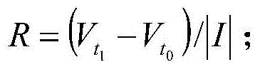
The battery internal resistance calculation method comprises the following steps:
wherein R is the internal resistance of the battery,
respectively corresponding the first and second data at the initial stage of charging, wherein I is t
1The time current value.
The battery differential pressure calculation method comprises the following steps:
Vdiff=voltmax-voltmin;
wherein, VdiffFor cell differential pressure, voltmaxIs the maximum voltage of the cell in the battery packminThe minimum value of the cell voltage in the battery pack.
The specific value of the battery pressure difference index is that the battery pressure difference V under certain working condition is metdiffThe value of (c).
The battery temperature difference calculation method comprises the following steps:
tempdiff=tempmax-tempmin;
wherein temp. isdiffFor cell temperature difference, tempmaxIs the maximum value in the temperature array, tempminIs the minimum value of the temperature array.
The specific value of the battery temperature difference index is the battery temperature difference temp meeting a certain working conditiondiffThe value of (c).
And substituting the corresponding charging monitoring data between the charging start bit and the charging end bit recorded in the one-time complete charging process into the calculation formula to calculate each battery performance index of the power battery.
The calculation process of the battery performance index will be described with the charging monitoring data in table 1 as an example. Since the conclusion is made that there is a complete and normal charging behavior between the 5 th to 19 th data in the above charging behavior determination step, the calculation is performed only based on the data of the charging section. And accumulating and calculating the charging times, and calculating the temperature at the charging starting moment as follows:
temp1=25;
the highest temperature in the charging section is:
temp2=max({25,25,26,26,26,26,27,27,28,28,28,27,27,26,26})=28;
the charging temperature rise is as follows:
tempincrease=temp2-temp1=3;
the battery capacity is:
when the internal resistance of the battery is calculated in the present embodiment, t is selected respectively0And t1Calculating the first piece of data and the second piece of data at the beginning of charging, wherein the calculation result is as follows:
in this example, when the battery differential pressure is calculated, the first piece of data is selected when the substitution operating condition is set to SOC 80, and the battery differential pressure is set to:
Vdiff=0.013V;
in this example, when the battery temperature difference is calculated, the first piece of data is selected when the substitution operating condition value is SOC equal to 80, and then the battery temperature difference value is:
tempdiff=5℃;
charging reference data of charging identification is summarized according to the calculation results, and a data table for summarizing the calculation results of charging identification refers to table 2.
Table 2 statistics of charging identification calculation results table 1
As can be seen from table 2, the charging behavior analyzed this time is 27 th charging operation, and the time between the 27 th charging operation and the last charging operation, i.e., the 26 th charging operation, is 12min, which is greater than the first preset time, i.e., the charging behavior of this time and the last charging behavior are not short interval behaviors. In addition, the duration of the current charging is 7min, which is longer than the second preset time, that is, the current charging behavior is not a short-time behavior, so that the current charging behavior can be judged as a complete and effective charging behavior.
The temperature of the battery pack at the beginning of the charging action is 25 ℃; the highest temperature reached by the battery pack in the charging action is 28 ℃; the temperature rise of the current charging behavior is 3 ℃ when the charging starting temperature is compared with the charging highest temperature; calculating the battery capacity of the power battery to be 176.083Ah according to the charging monitoring data of the current charging; the internal resistance of the power battery is 0.0634 omega; the battery pressure difference of the power battery is 0.013V; the temperature difference of the power battery is 5 ℃. By analyzing the battery performance index of the power battery in the identification and calculation result of the charging behavior, whether the power battery is abnormal or not can be judged, and further, all the battery packs with problems can be screened out by utilizing the monitoring method provided by the invention.
In one embodiment, the present invention is illustrated using another set of actual charge monitoring data, but should not be construed as limiting the scope of the invention. The second group of remote monitoring data of electric vehicles is shown in table 3.
Table 3 remote monitoring data recording table 2 for electric vehicle
In table 3, data items 3, 22, and 35 represent the omission of intermediate charge state duplication. The monitoring data of the charging behavior comprises a charging state, data acquisition time, a maximum temperature value, SOC, total voltage, a cell voltage difference (V) and a battery temperature difference (DEG C). In addition, 1 in the charging state represents that charging is in progress, 3 represents that charging is not in progress, the data acquisition time represents the uploading time of the data, and the highest temperature value represents the highest temperature value in the temperature probe in the battery pack at the moment.
Firstly, the change condition of the charging state is judged according to the change condition of the charging state in the charging monitoring data table. The charging state in the 2 nd data is changed from charging to non-charging, so the time of the data is marked as charging end bit 1; the charging state in the 5 th data is changed from uncharged to charging, so the time of the data is marked as charging start bit 1; the charging status in the 19 th data is changed from charging to non-charging, so the time of the data is marked as end-of-charge bit 2; the charging state in the 24 th data is changed from uncharged to charging, so the time of the data is marked as charging start bit 2; the charging status in the 33 rd data is changed from charging to non-charging, so the time of the data is marked as charging end bit 3; the charging state in the 37 th data is changed from charging to non-charging, and therefore the time of the data is marked as the charging start bit 3. And recording the charging monitoring data between the charging start bit and the charging end bit.
Secondly, the charging behavior is determined according to the valid charging monitoring data between the marked charging start bit and the marked charging end bit. In this example, θ1Has a value of 5min, [ theta ]2The value of (2) was 2 min. Recording the data acquisition time corresponding to the charging end bit 1 as t0The data acquisition time corresponding to the charge start bit 1 is denoted as t1Recording the data acquisition time corresponding to the charge end bit 2 as t2Setting the data acquisition time corresponding to the charging start bit 2 as t3Recording the data acquisition time corresponding to the charge end bit 3 as t4The data acquisition time corresponding to the charging start bit 3 is denoted as t5. Then the process of the first step is carried out,
tinterval1=t1-t0=12.5min>θ1;
the time interval between the charging start bit 1 and the charging end bit 1 of the last charging action is greater than the first preset time, so that it can be determined that the charging action of the time marked as charging start with the charging start bit 1 is a normal charging start action.
tinterval2=t3-t2=2.5min<θ1;
The time interval between the charging start bit 2 and the charging end bit 2 of the last charging action is less than the first preset time, so that it can be determined that the charging action of the time marked as charging start with the charging start bit 2 and the last charging action are short interval actions, and therefore, the charging actions are regarded as the same charging action. t is t2The charging behavior corresponding to the moment is not finished yet.
tinterval3=t5-t4=1476.5min>θ1;
The time interval between the charging start bit 3 and the charging end bit 3 of the last charging action is greater than the first preset time, so that t can be determined4The charging behavior corresponding to the time has ended, and the charging behavior marked with the charging start bit 3 as charging start is a normal charging start behavior.
tcontinues1=t4-t1=14min>θ2;
The charging operation lasts from the charging start bit 1 to the charging end bit 3, and the time difference between the charging end bit 3 and the charging start bit 1 is the duration of the charging operation. The duration time of the charging action is longer than the second preset time, so that the charging action is not a short-time action. Therefore, a complete and normal charging behavior between the 5 th data and the 33 th data can be judged, and the data in the charging process can be recorded.
And substituting the effective data of the charging section into the calculation formula to calculate, and obtaining the battery performance index of the power battery.
And accumulating and calculating the charging times, and calculating the temperature at the charging starting moment as follows:
temp1=25;
the highest temperature in the charging section is:
temp2=max({25,25,26,26,26,26,27,27,28,28,28,27,27,26,26,26,26,25,25,26,26,27,27,28,28,27,27,27})=28
the charging temperature rise is as follows:
tempincrease=temp2-temp1=3;
the battery capacity is:
when the internal resistance of the battery is calculated in the present embodiment, t is selected respectively0And t1Calculating the first piece of data and the second piece of data at the beginning of charging, wherein the calculation result is as follows:
in this example, when the battery differential pressure is calculated, the first piece of data is selected when the substitution operating condition is set to SOC 80, and the battery differential pressure is set to:
Vdiff=0.013V;
in this example, when the battery temperature difference is calculated, the first piece of data is selected when the substitution operating condition value is SOC equal to 80, and then the battery temperature difference value is:
tempdiff=5℃;
charging reference data of charging identification is summarized according to the calculation results, and a data table for summarizing the calculation results of charging identification refers to table 4.
Table 4 statistics of charging identification calculation results table 2
As can be seen from table 4, the charging behavior analyzed this time is the 29 th charging operation, and the time between the 29 th charging operation and the last charging operation, i.e., the 26 th charging operation, is 13min, which is greater than the first preset time, i.e., the charging behavior of this time and the last charging behavior are not short interval behaviors. In addition, the duration of the current charging is 19min, which is longer than the second preset time, that is, the current charging behavior is not a short-time behavior, so that the current charging behavior can be determined as a complete and effective charging behavior.
The temperature of the battery pack at the beginning of the charging action is 25 ℃; the highest temperature reached by the battery pack in the charging action is 28 ℃; the temperature rise of the current charging behavior is 3 ℃ when the charging starting temperature is compared with the charging highest temperature; calculating the battery capacity of the power battery to be 170.133Ah according to the charging monitoring data of the current charging; the internal resistance of the power battery is 0.0634 omega; the battery pressure difference of the power battery is 0.013V; the temperature difference of the power battery is 5 ℃. By analyzing the battery performance index of the power battery in the identification and calculation result of the charging behavior, whether the power battery is abnormal or not can be judged, and further, all the battery packs with problems can be screened out by utilizing the monitoring method provided by the invention.
The technical features of the embodiments described above may be arbitrarily combined, and for the sake of brevity, all possible combinations of the technical features in the embodiments described above are not described, but should be considered as being within the scope of the present specification as long as there is no contradiction between the combinations of the technical features.
The above-mentioned embodiments only express several embodiments of the present invention, and the description thereof is more specific and detailed, but not construed as limiting the scope of the invention. It should be noted that, for a person skilled in the art, several variations and modifications can be made without departing from the inventive concept, which falls within the scope of the present invention. Therefore, the protection scope of the present patent shall be subject to the appended claims.