CN111126154A - Method and device for identifying road surface element, unmanned equipment and storage medium - Google Patents
Method and device for identifying road surface element, unmanned equipment and storage medium Download PDFInfo
- Publication number
- CN111126154A CN111126154A CN201911166070.3A CN201911166070A CN111126154A CN 111126154 A CN111126154 A CN 111126154A CN 201911166070 A CN201911166070 A CN 201911166070A CN 111126154 A CN111126154 A CN 111126154A
- Authority
- CN
- China
- Prior art keywords
- image
- position information
- road surface
- current
- pavement
- Prior art date
- Legal status (The legal status is an assumption and is not a legal conclusion. Google has not performed a legal analysis and makes no representation as to the accuracy of the status listed.)
- Pending
Links
Images


Classifications
-
- G—PHYSICS
- G06—COMPUTING OR CALCULATING; COUNTING
- G06V—IMAGE OR VIDEO RECOGNITION OR UNDERSTANDING
- G06V20/00—Scenes; Scene-specific elements
- G06V20/50—Context or environment of the image
- G06V20/56—Context or environment of the image exterior to a vehicle by using sensors mounted on the vehicle
- G06V20/588—Recognition of the road, e.g. of lane markings; Recognition of the vehicle driving pattern in relation to the road
-
- G—PHYSICS
- G06—COMPUTING OR CALCULATING; COUNTING
- G06F—ELECTRIC DIGITAL DATA PROCESSING
- G06F16/00—Information retrieval; Database structures therefor; File system structures therefor
- G06F16/50—Information retrieval; Database structures therefor; File system structures therefor of still image data
- G06F16/58—Retrieval characterised by using metadata, e.g. metadata not derived from the content or metadata generated manually
- G06F16/583—Retrieval characterised by using metadata, e.g. metadata not derived from the content or metadata generated manually using metadata automatically derived from the content
-
- G—PHYSICS
- G06—COMPUTING OR CALCULATING; COUNTING
- G06F—ELECTRIC DIGITAL DATA PROCESSING
- G06F16/00—Information retrieval; Database structures therefor; File system structures therefor
- G06F16/50—Information retrieval; Database structures therefor; File system structures therefor of still image data
- G06F16/58—Retrieval characterised by using metadata, e.g. metadata not derived from the content or metadata generated manually
- G06F16/587—Retrieval characterised by using metadata, e.g. metadata not derived from the content or metadata generated manually using geographical or spatial information, e.g. location
Landscapes
- Engineering & Computer Science (AREA)
- Theoretical Computer Science (AREA)
- Physics & Mathematics (AREA)
- General Physics & Mathematics (AREA)
- Library & Information Science (AREA)
- Data Mining & Analysis (AREA)
- Databases & Information Systems (AREA)
- General Engineering & Computer Science (AREA)
- Multimedia (AREA)
- Image Processing (AREA)
Abstract
The application discloses a method and a device for identifying a road surface element, unmanned equipment and a storage medium. The method comprises the following steps: acquiring a current image; judging whether the current image meets a replacement condition; if the current image meets the replacement condition, finding out a replacement image matched with the current image from a pavement element image library according to the current image and the current position information; the pavement element image library stores pavement element images and corresponding position information thereof; identifying a pavement element for reference from the alternative image according to a pavement element image identification model; and determining the road surface element corresponding to the current position information in the current image according to the current position information, the position information corresponding to the replacement image and the road surface element for reference. The method has the advantages that when the current image does not meet the identification requirement, accurate pavement elements can be obtained through replacing the image, and the method is suitable for scenes such as unmanned driving.
Description
Technical Field
The application relates to the field of unmanned driving, in particular to a method and a device for identifying road surface elements, unmanned equipment and a storage medium.
Background
Unmanned vehicles are increasingly used in logistics, takeaway, and other fields, such as the distribution of goods or takeaway using unmanned vehicles. An important step in the unmanned scene is to effectively identify the current environment in which the unmanned device is located. There are currently two ways to implement: the method depends on a high-precision map, and the high-precision map has the defects of high precision, high refresh rate, more map elements, more available information, higher construction cost and the like. Secondly, a camera is used for identifying road traffic marking lines, road boundaries and the like, local mapping is carried out based on identification contents, and mapping results are generally called as perception maps. However, the use of the perception map depends on the image collected by the sensor, and if the road traffic marking in the image is blocked, the problem that the road traffic marking cannot be effectively identified exists.
Disclosure of Invention
In view of the above, the present application has been made to provide a method, an apparatus, an unmanned aerial device, and a storage medium for identifying a road surface element that overcome or at least partially solve the above-mentioned problems.
According to an aspect of the present application, there is provided a method of identifying a road surface element, including:
acquiring a current image;
judging whether the current image meets a replacement condition;
if the current image meets the replacement condition, finding out a replacement image matched with the current image from a pavement element image library according to the current image and the current position information; the pavement element image library stores pavement element images and corresponding position information thereof;
identifying a pavement element for reference from the alternative image according to a pavement element image identification model;
and determining the road surface element corresponding to the current position information in the current image according to the current position information, the position information corresponding to the replacement image and the road surface element for reference.
Optionally, the pavement element comprises a road traffic marking and/or a road boundary.
Optionally, the determining whether the current image satisfies a replacement condition includes:
judging whether the current image has a shielded lane line, if so, judging that the current image meets a replacement condition;
otherwise, inputting the current image into the pavement element image recognition model, and if the confidence coefficient of the recognition result is not greater than a preset threshold value, judging that the current image meets the replacement condition.
Optionally, the method further comprises:
and if the confidence of the recognition result is greater than a preset threshold, directly taking the recognition result as the road surface element corresponding to the current position information.
Optionally, the position information includes abscissa information, ordinate information, and angle information determined based on a preset coordinate system;
the road surface element includes a plurality of pairs of abscissa information and ordinate information determined based on the preset coordinate system.
Optionally, the determining, according to the current position information, the position information corresponding to the replacement image, and the road surface element for reference, the road surface element corresponding to the current position information includes:
determining a transformation matrix according to the current position information and the position information corresponding to the replacement image;
and determining the road surface element corresponding to the current position information according to the coordinate change matrix and the road surface element for reference.
Optionally, the method further comprises:
and taking the identified road surface elements as scene information, and planning the track of the unmanned equipment and/or constructing a map according to the scene information.
According to another aspect of the present application, there is provided a road surface element identification device including:
an acquisition unit configured to acquire a current image;
the road surface element identification unit is used for judging whether the current image meets a replacement condition; if the current image meets the replacement condition, finding out a replacement image matched with the current image from a pavement element image library according to the current image and the current position information; the pavement element image library stores pavement element images and corresponding position information thereof; identifying a pavement element for reference from the alternative image according to a pavement element image identification model; and determining the road surface element corresponding to the current position information in the current image according to the current position information, the position information corresponding to the replacement image and the road surface element for reference.
Optionally, the pavement element comprises a road traffic marking and/or a road boundary.
Optionally, the road surface element identification unit is configured to determine whether a shielded lane line exists in the current image, and if yes, determine that the current image meets a replacement condition; otherwise, inputting the current image into the pavement element image recognition model, and if the confidence coefficient of the recognition result is not greater than a preset threshold value, judging that the current image meets the replacement condition.
Optionally, the road surface element identification unit is configured to, if the confidence of the identification result is greater than a preset threshold, directly use the identification result as the road surface element corresponding to the current position information.
Optionally, the position information includes abscissa information, ordinate information, and angle information determined based on a preset coordinate system; the road surface element includes a plurality of pairs of abscissa information and ordinate information determined based on the preset coordinate system.
Optionally, the road surface element identification unit is configured to determine a transformation matrix according to the current position information and the position information corresponding to the replacement image; and determining the road surface element corresponding to the current position information according to the coordinate change matrix and the road surface element for reference.
Optionally, the apparatus further comprises: and the application unit is used for taking the identified road surface elements as scene information, and planning the track of the unmanned equipment and/or establishing a map according to the scene information.
In accordance with yet another aspect of the present application, there is provided an unmanned aerial vehicle comprising: a processor; and a memory arranged to store computer executable instructions that, when executed, cause the processor to perform a method as any one of the above.
According to a further aspect of the application, there is provided a computer readable storage medium, wherein the computer readable storage medium stores one or more programs which, when executed by a processor, implement a method as in any above.
According to the technical scheme, the current image is acquired; judging whether the current image meets a replacement condition; if the current image meets the replacement condition, finding out a replacement image matched with the current image from a pavement element image library according to the current image and the current position information; the pavement element image library stores pavement element images and corresponding position information thereof; identifying a pavement element for reference from the alternative image according to a pavement element image identification model; and determining the road surface element corresponding to the current position information according to the current position information, the position information corresponding to the replacement image and the road surface element for reference. The method has the advantages that the corresponding pavement elements can be automatically determined, the cost is low, the precision is high, the pavement elements can be efficiently identified, and a coping scheme with a good effect is provided for the situations that the pavement elements in the image are blocked and the like.
The foregoing description is only an overview of the technical solutions of the present application, and the present application can be implemented according to the content of the description in order to make the technical means of the present application more clearly understood, and the following detailed description of the present application is given in order to make the above and other objects, features, and advantages of the present application more clearly understandable.
Drawings
Various other advantages and benefits will become apparent to those of ordinary skill in the art upon reading the following detailed description of the preferred embodiments. The drawings are only for purposes of illustrating the preferred embodiments and are not to be construed as limiting the application. Also, like reference numerals are used to refer to like parts throughout the drawings. In the drawings:
fig. 1 shows a schematic flow diagram of a method for identifying a pavement element according to an embodiment of the application;
fig. 2 is a schematic structural view showing a road surface element recognition apparatus according to an embodiment of the present application;
FIG. 3 shows a schematic structural diagram of an unmanned aerial vehicle according to an embodiment of the present application;
FIG. 4 shows a schematic structural diagram of a computer-readable storage medium according to an embodiment of the present application.
Detailed Description
Exemplary embodiments of the present application will be described in more detail below with reference to the accompanying drawings. While exemplary embodiments of the present application are shown in the drawings, it should be understood that the present application may be embodied in various forms and should not be limited to the embodiments set forth herein. Rather, these embodiments are provided so that this disclosure will be thorough and complete, and will fully convey the scope of the disclosure to those skilled in the art.
Fig. 1 is a schematic flow chart illustrating a method for identifying a road surface element according to an embodiment of the present application. As shown in fig. 1, the method includes:
step S110, a current image is acquired.
The current image can be acquired by a sensor or transmitted by the V2X. V2X is vehicle to outside information exchange system, and can realize real-time traffic information collection by sensing surrounding environment by using vehicle-mounted sensor and camera system in unmanned driving mode.
That is to say, the road surface elements identified by the embodiment of the application can be used for planning the track of the unmanned equipment in real time, and can also be used for mapping and other scenes. The method of the embodiment of the application can be applied to the unmanned equipment or the mapping equipment correspondingly. The sensor may be a sensor arranged on the unmanned device, such as a camera, for detecting the road condition in real time, and acquiring a current image of the road surface, or at least partially acquiring the current image of the road surface. In this way, the acquisition of the current image of the road surface is achieved.
Step S120, determining whether the current image satisfies the replacement condition.
The previously collected clear and non-occluded images can be stored in the gallery in advance, and the conditions for replacing the current image are set in advance. When the acquired current image has defects such as over-blurring and being blocked, the current image can be replaced by a clear image in the image library through replacement so as to overcome the defects of the acquired image.
Step S130, if the current image meets the replacement condition, finding out a replacement image matched with the current image from the pavement element image library according to the current image and the current position information; the road surface element image library stores road surface element images and corresponding position information.
The collected current image has a corresponding relation with the current position information, and the road surface element image stored in the road surface element image library also has a corresponding relation with the position information. The position information can be high-precision positioning information, and the accuracy of positioning and subsequent matching is ensured. Therefore, in order to accurately replace the current image with flaws, a replacement image matched with the current image can be found from the road surface element image library according to the current image and the current position information when the replacement condition is met. In this way, accurate replacement of the corresponding current image with defects is achieved.
In step S140, a road surface element for reference is identified from the alternative image according to the road surface element image identification model.
In order to more efficiently identify the pavement elements in the pavement element image, a pavement element image identification model can be constructed in advance, and the pavement elements for reference can be identified from the alternative image according to the pavement element image identification model after model training is completed. In this way, accurate and automated recognition of the road surface elements for reference from the replacement image is achieved.
And step S150, determining the road surface element corresponding to the current position information in the current image according to the current position information, the position information corresponding to the replacement image and the road surface element for reference.
It is not realistic to store the images captured at all positions and at all angles in the road surface element image library, and therefore, although the replacement image is matched with the current image, the replacement image is not necessarily completely consistent with the current image, for example, there may be a deviation between the current position information and the position information corresponding to the replacement image, and it may not be practical to directly use the road surface element for reference, for example, there is an error of 5cm in the lateral direction between the current position information and the position information corresponding to the replacement image, and if the trajectory planning is performed according to the solid line identified in the replacement image, there is a high possibility of pressing the line in practice. Therefore, some conversion operations are required. Therefore, the road surface element corresponding to the current position information can be determined according to the corresponding relation between the current position information and the position information corresponding to the replacement image and by combining the road surface element for reference, and the road surface element corresponding to the current position information in the current image is completely analyzed and finally determined.
Therefore, the method shown in fig. 1 has the advantages that the corresponding road surface elements can be automatically determined, the cost is low, the precision is high, the road surface elements can be efficiently identified, and a response scheme with a good effect is provided for the situations that the road surface elements in the image are blocked and the like.
In one embodiment of the present application, the pavement elements include road traffic markings and/or road boundaries.
Road traffic markings and road boundaries have an important traffic guiding function, so that the road surface elements can comprise information contents such as the road traffic markings and the road boundaries.
In an embodiment of the application, the determining whether the current image satisfies the replacement condition includes: judging whether the current image has the shielded pavement elements or not, and if so, judging that the current image meets the replacement condition; otherwise, inputting the current image into the pavement element image recognition model, and if the confidence coefficient of the recognition result is not greater than a preset threshold value, judging that the current image meets the replacement condition.
The conditions that road surface elements are shielded, incomplete and unclear and the like may exist in the current image acquired by the sensor. Therefore, the determination can be made individually on a case-by-case basis. Specifically, it may be determined whether the occluded road surface element exists in the current image by first identifying and deriving, for example, through an image recognition algorithm, or through an automatic recognition model. If the road surface elements such as the shielded lane lines and the like exist in the current image, judging that the current image meets the replacement condition, and further starting a process of selecting the replacement image; and if the road elements such as the shielded lane lines and the like do not exist in the current image, inputting the current image into the road element image recognition model, and judging again through a preset road element image recognition model and a confidence coefficient preset threshold value. And comparing the recognition result obtained by analyzing the pavement element image recognition model with a confidence threshold, and if the obtained recognition result is not greater than a preset threshold, judging that the current image meets the replacement condition, and further starting a replacement image. When selecting a replacement image matching the road surface image, the search range may be defined by, for example, a gist scene descriptor, and the road surface image most similar to the current image is selected by an image matching algorithm. In this way, different alternative conditions are respectively determined by combining different specific road surface image conditions.
In an embodiment of the present application, the method further includes: and if the confidence coefficient of the recognition result is greater than a preset threshold value, directly taking the recognition result as the road surface element corresponding to the current position information.
And comparing the identification result obtained by analyzing the road element image identification model with a confidence threshold, and if the obtained identification result is greater than a preset threshold, determining that the obtained road image meets the identification requirement, and directly taking the identification result as the road element corresponding to the current position information. In this way, it is achieved that the road surface image satisfying the recognition requirement is processed to take the recognition result directly as the road surface element corresponding to the current position information.
In an embodiment of the present application, in the method, the position information includes abscissa information, ordinate information, and angle information determined based on a preset coordinate system; the road surface element includes a plurality of pairs of abscissa information and ordinate information determined based on a preset coordinate system.
The pavement elements may include road traffic markings and/or road boundaries, and to accurately describe these pavement elements, the corresponding location information may be further determined by determining the spatial location of the road traffic markings and/or road boundaries. The accuracy of the corresponding position relationship directly affects the accuracy of the road surface image replacement, and further affects the overall recognition effect. Therefore, in order to accurately describe the position information of the road surface image, a unified coordinate system may be established, and the abscissa information, the ordinate information, and the angle information (generally denoted as x, y, theta) determined based on the coordinate system are comprehensively described, wherein the angle information is included because the current position information also has a corresponding relationship with the pose of the sensor. The road surface element includes a plurality of pairs of abscissa information and ordinate information determined based on a preset coordinate system, and since the road surface element such as a road traffic marking is often present in a range, a plurality of coordinate pairs are corresponded. Thus, the accurate description of the spatial position relation can be realized.
In one embodiment of the present application, the determining, in the above method, a road surface element corresponding to the current position information, based on the current position information, the position information corresponding to the replacement image, and the road surface element for reference, includes: determining a transformation matrix according to the current position information and the position information corresponding to the replacement image; and determining the road surface element corresponding to the current position information according to the coordinate change matrix and the road surface element for reference.
The current position information and the space position of the replacement image have a corresponding relation, so that the current position information and the position information corresponding to the replacement image can be determined by analyzing and converting the corresponding position information. Specifically, the road surface element corresponding to the current position information may be determined by determining a transformation matrix and according to the coordinate change matrix and the road surface element for reference. For example, assuming that the matched road surface image is P _ m, the position coordinate of the matched road surface image is L _ m, the current road surface position coordinate is L _ c, and the coordinate of the Lane line obtained by the Lane line model is Lane _ m. The Lane line Lane _ m { (X _ left _1, Y _ left _1), ·, (X _ left _ n, Y _ left _ n) may be obtained from the Lane line model according to P _ m and its corresponding L _ m { (X _ m, Y _ m, Theta _ m); (X _ right _ n, Y _ left _ n) }. In this way, the Lane _ m coordinate of the Lane line is obtained through the Lane line model. Then, the transformation matrix R, T of L _ c to L _ m may be determined according to (X _ c, Y _ c, Theta _ c) and L _ m (X _ m, Y _ m, Theta _ m). From the matrices R, T, Lane _ c, which is the result of Lane _ m transformation, can be finally obtained. Therefore, the road surface element corresponding to the current position information is determined by means of matrix conversion according to the corresponding relation between the current position information and the space position of the replacement image.
In an embodiment of the application, in the method, the identified road surface element is used as scene information, and trajectory planning and/or mapping of the unmanned equipment is performed according to the scene information.
The identified road surface elements have an important auxiliary planning effect on the unmanned path planning. Specifically, the trajectory planning of the unmanned aerial vehicle can be performed by using the identified road surface elements as scene information and then performing trajectory planning on the unmanned aerial vehicle according to the scene information. Therefore, the unmanned equipment can accurately analyze the real-time traffic information according to the road surface elements, so that the surrounding environment is accurately sensed, the obstacles are avoided, the driving route with the best road condition is automatically selected, and automatic operations such as rapid adjustment, automatic deceleration to safe speed, steering or parking are automatically performed. In addition, the generated road surface elements can also be applied to the map building, and great help is provided for the auxiliary map drawing. Therefore, the scheme of the application has higher application value and adaptability to the fields of logistics, takeaway delivery and the like which depend on maps and path planning.
Fig. 2 is a schematic structural diagram showing a road surface element recognition apparatus according to an embodiment of the present application. As shown in fig. 2, the recognition apparatus 200 of a road surface element includes:
an obtaining unit 210, configured to obtain a current image.
The current image can be acquired by a sensor or transmitted by the V2X. V2X is vehicle to outside information exchange system, and can realize real-time traffic information collection by sensing surrounding environment by using vehicle-mounted sensor and camera system in unmanned driving mode.
That is to say, the road surface elements identified by the embodiment of the application can be used for planning the track of the unmanned equipment in real time, and can also be used for mapping and other scenes. The apparatus of the embodiment of the present application can be applied to the unmanned device or the image creating device accordingly. The sensor may be a sensor arranged on the unmanned device, such as a camera, for detecting the road condition in real time, and acquiring a current image of the road surface, or at least partially acquiring the current image of the road surface. In this way, the acquisition of the current image of the road surface is achieved.
A road surface element identification unit 220 for judging whether the current image satisfies the replacement condition; if the current image meets the replacement condition, finding out a replacement image matched with the current image from the pavement element image library according to the current image and the current position information; the pavement element image library stores pavement element images and corresponding position information thereof; identifying a pavement element for reference from the alternative image according to the pavement element image identification model; and determining the road surface element corresponding to the current position information in the current image according to the current position information, the position information corresponding to the replacement image and the road surface element for reference.
The previously collected clear and non-occluded images can be stored in the gallery in advance, and the conditions for replacing the current image are set in advance. When the acquired current image has defects such as over-blurring and being blocked, the current image can be replaced by a clear image in the image library through replacement so as to overcome the defects of the acquired image. The collected current image has a corresponding relation with the current position information, and the road surface element image stored in the road surface element image library also has a corresponding relation with the position information. The position information can be high-precision positioning information, and the accuracy of positioning and subsequent matching is ensured. Therefore, in order to accurately replace the current image with flaws, a replacement image matched with the current image can be found from the road surface element image library according to the current image and the current position information when the replacement condition is met. In this way, accurate replacement of the corresponding current image with defects is achieved. In order to more efficiently identify the pavement elements in the pavement element image, a pavement element image identification model can be constructed in advance, and the pavement elements for reference can be identified from the alternative image according to the pavement element image identification model after model training is completed. In this way, accurate and automated recognition of the road surface elements for reference from the replacement image is achieved. It is not realistic to store the images captured at all positions and at all angles in the road surface element image library, and therefore, although the replacement image is matched with the current image, the replacement image is not necessarily completely consistent with the current image, for example, there may be a deviation between the current position information and the position information corresponding to the replacement image, and it may not be practical to directly use the road surface element for reference, for example, there is an error of 5cm in the lateral direction between the current position information and the position information corresponding to the replacement image, and if the trajectory planning is performed according to the solid line identified in the replacement image, there is a high possibility of pressing the line in practice. Therefore, some conversion operations are required. Therefore, the road surface element corresponding to the current position information in the current image can be determined according to the corresponding relation between the current position information and the position information corresponding to the replacement image and by combining the road surface element for reference, and the road surface element corresponding to the current position information can be completely analyzed and finally determined.
Therefore, the device shown in fig. 2 has the advantages that the corresponding road surface elements can be automatically determined, the cost is low, the precision is high, the road surface elements can be efficiently identified, and a coping scheme with a good effect is provided for the conditions that the road surface elements in the image are blocked and the like.
In one embodiment of the present application, the pavement elements include road traffic markings and/or road boundaries.
In an embodiment of the present application, in the apparatus, the road surface element identification unit is configured to determine whether a masked road surface element exists in the current image, and if yes, determine that the current image satisfies the replacement condition; otherwise, inputting the current image into the pavement element image recognition model, and if the confidence coefficient of the recognition result is not greater than a preset threshold value, judging that the current image meets the replacement condition.
In an embodiment of the application, in the apparatus, the road surface element identification unit is configured to, if a confidence of the identification result is greater than a preset threshold, directly use the identification result as the road surface element corresponding to the current position information.
In an embodiment of the present application, in the above apparatus, the position information includes abscissa information, ordinate information, and angle information determined based on a preset coordinate system; the road surface element includes a plurality of pairs of abscissa information and ordinate information determined based on a preset coordinate system.
In an embodiment of the present application, in the apparatus, the road surface element identification unit is configured to determine a transformation matrix according to the current position information and the position information corresponding to the replacement image; and determining the road surface element corresponding to the current position information according to the coordinate change matrix and the road surface element for reference.
In one embodiment of the present application, the apparatus further includes: and the application unit is used for taking the identified road surface elements as scene information, and planning the track of the unmanned equipment and/or establishing a map according to the scene information.
It should be noted that, for the specific implementation of each apparatus embodiment, reference may be made to the specific implementation of the corresponding method embodiment, which is not described herein again.
In summary, according to the technical scheme of the application, the current image is obtained; judging whether the current image meets a replacement condition; if the current image meets the replacement condition, finding out a replacement image matched with the current image from a pavement element image library according to the current image and the current position information; the pavement element image library stores pavement element images and corresponding position information thereof; identifying a pavement element for reference from the alternative image according to a pavement element image identification model; and determining the road surface element corresponding to the current position information according to the current position information, the position information corresponding to the replacement image and the road surface element for reference. The method has the advantages that the corresponding pavement elements can be automatically determined, the cost is low, the precision is high, the pavement elements can be efficiently identified, and a coping scheme with a good effect is provided for the situations that the pavement elements in the image are blocked and the like.
It should be noted that:
the algorithms and displays presented herein are not inherently related to any particular computer, virtual machine, or other apparatus. Various general purpose devices may be used with the teachings herein. The required structure for constructing such a device will be apparent from the description above. In addition, this application is not directed to any particular programming language. It will be appreciated that a variety of programming languages may be used to implement the teachings of the present application as described herein, and any descriptions of specific languages are provided above to disclose the best modes of the present application.
In the description provided herein, numerous specific details are set forth. However, it is understood that embodiments of the application may be practiced without these specific details. In some instances, well-known methods, structures and techniques have not been shown in detail in order not to obscure an understanding of this description.
Similarly, it should be appreciated that in the foregoing description of exemplary embodiments of the application, various features of the application are sometimes grouped together in a single embodiment, figure, or description thereof for the purpose of streamlining the application and aiding in the understanding of one or more of the various inventive aspects. However, the disclosed method should not be interpreted as reflecting an intention that: this application is intended to cover such departures from the present disclosure as come within known or customary practice in the art to which this invention pertains. Rather, as the following claims reflect, inventive aspects lie in less than all features of a single foregoing disclosed embodiment. Thus, the claims following the detailed description are hereby expressly incorporated into this detailed description, with each claim standing on its own as a separate embodiment of this application.
Those skilled in the art will appreciate that the modules in the device in an embodiment may be adaptively changed and disposed in one or more devices different from the embodiment. The modules or units or components of the embodiments may be combined into one module or unit or component, and furthermore they may be divided into a plurality of sub-modules or sub-units or sub-components. All of the features disclosed in this specification (including any accompanying claims, abstract and drawings), and all of the processes or elements of any method or apparatus so disclosed, may be combined in any combination, except combinations where at least some of such features and/or processes or elements are mutually exclusive. Each feature disclosed in this specification (including any accompanying claims, abstract and drawings) may be replaced by alternative features serving the same, equivalent or similar purpose, unless expressly stated otherwise.
Furthermore, those skilled in the art will appreciate that while some embodiments described herein include some features included in other embodiments, rather than other features, combinations of features of different embodiments are meant to be within the scope of the application and form different embodiments. For example, in the following claims, any of the claimed embodiments may be used in any combination.
The various component embodiments of the present application may be implemented in hardware, or in software modules running on one or more processors, or in a combination thereof. It will be appreciated by those skilled in the art that a microprocessor or Digital Signal Processor (DSP) may be used in practice to implement some or all of the functions of some or all of the components of the device for identifying pavement elements according to embodiments of the present application. The present application may also be embodied as apparatus or device programs (e.g., computer programs and computer program products) for performing a portion or all of the methods described herein. Such programs implementing the present application may be stored on a computer readable medium or may be in the form of one or more signals. Such a signal may be downloaded from an internet website or provided on a carrier signal or in any other form.
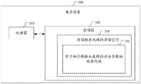
For example, fig. 3 shows a schematic structural diagram of an electronic device according to an embodiment of the present application. The electronic device 300 comprises a processor 310 and a memory 320 arranged to store computer executable instructions (computer readable program code). The memory 320 may be an electronic memory such as a flash memory, an EEPROM (electrically erasable programmable read only memory), an EPROM, a hard disk, or a ROM. The memory 320 has a storage space 330 storing computer readable program code 331 for performing any of the method steps described above. For example, the storage space 330 for storing the computer readable program code may comprise respective computer readable program codes 331 for respectively implementing various steps in the above method. The computer readable program code 331 may be read from or written to one or more computer program products. These computer program products comprise a program code carrier such as a hard disk, a Compact Disc (CD), a memory card or a floppy disk. Such a computer program product is typically a computer readable storage medium such as described in fig. 4. FIG. 4 shows a schematic structural diagram of a computer-readable storage medium according to an embodiment of the present application. The computer readable storage medium 400 has stored thereon a computer readable program code 331 for performing the steps of the method according to the application, readable by a processor 310 of an electronic device 300, which computer readable program code 331, when executed by the electronic device 300, causes the electronic device 300 to perform the steps of the method described above, in particular the computer readable program code 331 stored on the computer readable storage medium may perform the method shown in any of the embodiments described above. The computer readable program code 331 may be compressed in a suitable form.
It should be noted that the above-mentioned embodiments illustrate rather than limit the application, and that those skilled in the art will be able to design alternative embodiments without departing from the scope of the appended claims. In the claims, any reference signs placed between parentheses shall not be construed as limiting the claim. The word "comprising" does not exclude the presence of elements or steps not listed in a claim. The word "a" or "an" preceding an element does not exclude the presence of a plurality of such elements. The application may be implemented by means of hardware comprising several distinct elements, and by means of a suitably programmed computer. In the unit claims enumerating several means, several of these means may be embodied by one and the same item of hardware. The usage of the words first, second and third, etcetera do not indicate any ordering. These words may be interpreted as names.
Claims (10)
1. A method of identifying a pavement element, comprising:
acquiring a current image;
judging whether the current image meets a replacement condition;
if the current image meets the replacement condition, finding out a replacement image matched with the current image from a pavement element image library according to the current image and the current position information; the pavement element image library stores pavement element images and corresponding position information thereof;
identifying a pavement element for reference from the alternative image according to a pavement element image identification model;
and determining the road surface element corresponding to the current position information in the current image according to the current position information, the position information corresponding to the replacement image and the road surface element for reference.
2. The method of claim 1, wherein the pavement elements comprise road traffic markings and/or road boundaries.
3. The method of claim 1, wherein the determining whether the current image satisfies a replacement condition comprises:
judging whether the current image has the shielded pavement elements or not, and if so, judging that the current image meets the replacement condition;
otherwise, inputting the current image into the pavement element image recognition model, and if the confidence coefficient of the recognition result is not greater than a preset threshold value, judging that the current image meets the replacement condition.
4. The method of claim 3, wherein the method further comprises:
and if the confidence of the recognition result is greater than a preset threshold, directly taking the recognition result as the road surface element corresponding to the current position information.
5. The method of claim 1, wherein the position information includes abscissa information, ordinate information, and angle information determined based on a preset coordinate system;
the road surface element includes a plurality of pairs of abscissa information and ordinate information determined based on the preset coordinate system.
6. The method of claim 5, wherein the determining the road surface element corresponding to the current position information based on the current position information, the position information corresponding to the replacement image, and the road surface element for reference comprises:
determining a transformation matrix according to the current position information and the position information corresponding to the replacement image;
and determining the road surface element corresponding to the current position information according to the coordinate change matrix and the road surface element for reference.
7. The method of claim 1, wherein the method further comprises:
and taking the identified road surface elements as scene information, and planning the track of the unmanned equipment and/or constructing a map according to the scene information.
8. An identification device for pavement elements, comprising:
an acquisition unit configured to acquire a current image;
the road surface element identification unit is used for judging whether the current image meets a replacement condition; if the current image meets the replacement condition, finding out a replacement image matched with the current image from a pavement element image library according to the current image and the current position information; the pavement element image library stores pavement element images and corresponding position information thereof; identifying a pavement element for reference from the alternative image according to a pavement element image identification model; and determining the road surface element corresponding to the current position information according to the current position information, the position information corresponding to the replacement image and the road surface element for reference.
9. An unmanned aerial device, comprising: a processor; and a memory arranged to store computer-executable instructions that, when executed, cause the processor to perform the method of any one of claims 1-7.
10. A computer readable storage medium, wherein the computer readable storage medium stores one or more programs which, when executed by a processor, implement the method of any of claims 1-7.
Priority Applications (1)
| Application Number | Priority Date | Filing Date | Title |
|---|---|---|---|
| CN201911166070.3A CN111126154A (en) | 2019-11-25 | 2019-11-25 | Method and device for identifying road surface element, unmanned equipment and storage medium |
Applications Claiming Priority (1)
| Application Number | Priority Date | Filing Date | Title |
|---|---|---|---|
| CN201911166070.3A CN111126154A (en) | 2019-11-25 | 2019-11-25 | Method and device for identifying road surface element, unmanned equipment and storage medium |
Publications (1)
| Publication Number | Publication Date |
|---|---|
| CN111126154A true CN111126154A (en) | 2020-05-08 |
Family
ID=70496604
Family Applications (1)
| Application Number | Title | Priority Date | Filing Date |
|---|---|---|---|
| CN201911166070.3A Pending CN111126154A (en) | 2019-11-25 | 2019-11-25 | Method and device for identifying road surface element, unmanned equipment and storage medium |
Country Status (1)
| Country | Link |
|---|---|
| CN (1) | CN111126154A (en) |
Cited By (2)
| Publication number | Priority date | Publication date | Assignee | Title |
|---|---|---|---|---|
| CN111783651A (en) * | 2020-06-30 | 2020-10-16 | 北京百度网讯科技有限公司 | Pavement element identification method, device, electronic device and storage medium |
| CN114554113A (en) * | 2022-04-24 | 2022-05-27 | 浙江华眼视觉科技有限公司 | Express item code recognition machine express item person drawing method and device |
Citations (9)
| Publication number | Priority date | Publication date | Assignee | Title |
|---|---|---|---|---|
| JP2010108049A (en) * | 2008-10-28 | 2010-05-13 | Hitachi Automotive Systems Ltd | Road marking recognition device |
| KR20140137100A (en) * | 2013-05-22 | 2014-12-02 | 숭실대학교산학협력단 | Lane detection system and method thereof |
| CN105807296A (en) * | 2014-12-31 | 2016-07-27 | 中国移动通信集团公司 | Vehicle positioning method and device and vehicle positioning equipment |
| CN106294458A (en) * | 2015-05-29 | 2017-01-04 | 北京四维图新科技股份有限公司 | A kind of map point of interest update method and device |
| CN109186615A (en) * | 2018-09-03 | 2019-01-11 | 武汉中海庭数据技术有限公司 | Lane side linear distance detection method, device and storage medium based on high-precision map |
| CN109658445A (en) * | 2018-12-14 | 2019-04-19 | 北京旷视科技有限公司 | Network training method, increment build drawing method, localization method, device and equipment |
| CN109902637A (en) * | 2019-03-05 | 2019-06-18 | 长沙智能驾驶研究院有限公司 | Lane line detection method, device, computer equipment and storage medium |
| CN109916415A (en) * | 2019-04-12 | 2019-06-21 | 北京百度网讯科技有限公司 | Road type determines method, apparatus, equipment and storage medium |
| CN109949414A (en) * | 2019-01-31 | 2019-06-28 | 顺丰科技有限公司 | The construction method and device of indoor map |
-
2019
- 2019-11-25 CN CN201911166070.3A patent/CN111126154A/en active Pending
Patent Citations (9)
| Publication number | Priority date | Publication date | Assignee | Title |
|---|---|---|---|---|
| JP2010108049A (en) * | 2008-10-28 | 2010-05-13 | Hitachi Automotive Systems Ltd | Road marking recognition device |
| KR20140137100A (en) * | 2013-05-22 | 2014-12-02 | 숭실대학교산학협력단 | Lane detection system and method thereof |
| CN105807296A (en) * | 2014-12-31 | 2016-07-27 | 中国移动通信集团公司 | Vehicle positioning method and device and vehicle positioning equipment |
| CN106294458A (en) * | 2015-05-29 | 2017-01-04 | 北京四维图新科技股份有限公司 | A kind of map point of interest update method and device |
| CN109186615A (en) * | 2018-09-03 | 2019-01-11 | 武汉中海庭数据技术有限公司 | Lane side linear distance detection method, device and storage medium based on high-precision map |
| CN109658445A (en) * | 2018-12-14 | 2019-04-19 | 北京旷视科技有限公司 | Network training method, increment build drawing method, localization method, device and equipment |
| CN109949414A (en) * | 2019-01-31 | 2019-06-28 | 顺丰科技有限公司 | The construction method and device of indoor map |
| CN109902637A (en) * | 2019-03-05 | 2019-06-18 | 长沙智能驾驶研究院有限公司 | Lane line detection method, device, computer equipment and storage medium |
| CN109916415A (en) * | 2019-04-12 | 2019-06-21 | 北京百度网讯科技有限公司 | Road type determines method, apparatus, equipment and storage medium |
Cited By (3)
| Publication number | Priority date | Publication date | Assignee | Title |
|---|---|---|---|---|
| CN111783651A (en) * | 2020-06-30 | 2020-10-16 | 北京百度网讯科技有限公司 | Pavement element identification method, device, electronic device and storage medium |
| CN111783651B (en) * | 2020-06-30 | 2024-01-12 | 北京百度网讯科技有限公司 | Pavement element identification method, device, electronic equipment and storage medium |
| CN114554113A (en) * | 2022-04-24 | 2022-05-27 | 浙江华眼视觉科技有限公司 | Express item code recognition machine express item person drawing method and device |
Similar Documents
| Publication | Publication Date | Title |
|---|---|---|
| CN110758246B (en) | Automatic parking method and device | |
| CN112069643B (en) | Automatic driving simulation scene generation method and device | |
| CN110210280B (en) | Beyond-visual-range sensing method, beyond-visual-range sensing system, terminal and storage medium | |
| CN108303103B (en) | Method and device for determining target lane | |
| JP7645258B2 (en) | Map data updates | |
| US8611585B2 (en) | Clear path detection using patch approach | |
| CN106952308B (en) | Method and system for determining position of moving object | |
| CN111401133A (en) | Target data augmentation method, device, electronic device and readable storage medium | |
| CN104036279A (en) | Intelligent vehicle running control method and system | |
| US20210191397A1 (en) | Autonomous vehicle semantic map establishment system and establishment method | |
| CN112654997B (en) | A kind of lane line detection method and device | |
| CN112487861A (en) | Lane line recognition method and device, computing equipment and computer storage medium | |
| CN111079680A (en) | Temporary traffic signal lamp detection method and device and automatic driving equipment | |
| CN110515376B (en) | Evaluation method, terminal and storage medium for track deduction correction | |
| WO2020007589A1 (en) | Training a deep convolutional neural network for individual routes | |
| CN111325136B (en) | Method and device for labeling object in intelligent vehicle and unmanned vehicle | |
| CN112820141B (en) | Parking space detection method and system | |
| CN117576652A (en) | Road object identification method and device, storage medium and electronic equipment | |
| CN113033253B (en) | Camera calibration method and device | |
| CN116664498B (en) | Training methods for parking space detection models, parking space detection methods, devices and equipment | |
| CN111126154A (en) | Method and device for identifying road surface element, unmanned equipment and storage medium | |
| CN119169590B (en) | Perception model evaluation method and device, storage medium and electronic device | |
| CN116543360B (en) | Methods, devices and electronic equipment for constructing roadside maps | |
| CN119169413A (en) | Method and device for determining evaluation data, storage medium and electronic device | |
| CN108022250B (en) | Automatic driving processing method and device based on self-adaptive threshold segmentation |
Legal Events
| Date | Code | Title | Description |
|---|---|---|---|
| PB01 | Publication | ||
| PB01 | Publication | ||
| SE01 | Entry into force of request for substantive examination | ||
| SE01 | Entry into force of request for substantive examination | ||
| WD01 | Invention patent application deemed withdrawn after publication | ||
| WD01 | Invention patent application deemed withdrawn after publication |
Application publication date: 20200508 |