CN110721384A - Patient Interfaces and Parts - Google Patents
Patient Interfaces and Parts Download PDFInfo
- Publication number
- CN110721384A CN110721384A CN201910978538.2A CN201910978538A CN110721384A CN 110721384 A CN110721384 A CN 110721384A CN 201910978538 A CN201910978538 A CN 201910978538A CN 110721384 A CN110721384 A CN 110721384A
- Authority
- CN
- China
- Prior art keywords
- manifold
- patient interface
- arms
- frame
- arm
- Prior art date
- Legal status (The legal status is an assumption and is not a legal conclusion. Google has not performed a legal analysis and makes no representation as to the accuracy of the status listed.)
- Granted
Links
Images


Classifications
-
- A—HUMAN NECESSITIES
- A61—MEDICAL OR VETERINARY SCIENCE; HYGIENE
- A61M—DEVICES FOR INTRODUCING MEDIA INTO, OR ONTO, THE BODY; DEVICES FOR TRANSDUCING BODY MEDIA OR FOR TAKING MEDIA FROM THE BODY; DEVICES FOR PRODUCING OR ENDING SLEEP OR STUPOR
- A61M16/00—Devices for influencing the respiratory system of patients by gas treatment, e.g. ventilators; Tracheal tubes
- A61M16/06—Respiratory or anaesthetic masks
- A61M16/0666—Nasal cannulas or tubing
-
- A—HUMAN NECESSITIES
- A61—MEDICAL OR VETERINARY SCIENCE; HYGIENE
- A61M—DEVICES FOR INTRODUCING MEDIA INTO, OR ONTO, THE BODY; DEVICES FOR TRANSDUCING BODY MEDIA OR FOR TAKING MEDIA FROM THE BODY; DEVICES FOR PRODUCING OR ENDING SLEEP OR STUPOR
- A61M16/00—Devices for influencing the respiratory system of patients by gas treatment, e.g. ventilators; Tracheal tubes
- A61M16/0057—Pumps therefor
- A61M16/0066—Blowers or centrifugal pumps
-
- A—HUMAN NECESSITIES
- A61—MEDICAL OR VETERINARY SCIENCE; HYGIENE
- A61M—DEVICES FOR INTRODUCING MEDIA INTO, OR ONTO, THE BODY; DEVICES FOR TRANSDUCING BODY MEDIA OR FOR TAKING MEDIA FROM THE BODY; DEVICES FOR PRODUCING OR ENDING SLEEP OR STUPOR
- A61M16/00—Devices for influencing the respiratory system of patients by gas treatment, e.g. ventilators; Tracheal tubes
- A61M16/021—Devices for influencing the respiratory system of patients by gas treatment, e.g. ventilators; Tracheal tubes operated by electrical means
-
- A—HUMAN NECESSITIES
- A61—MEDICAL OR VETERINARY SCIENCE; HYGIENE
- A61M—DEVICES FOR INTRODUCING MEDIA INTO, OR ONTO, THE BODY; DEVICES FOR TRANSDUCING BODY MEDIA OR FOR TAKING MEDIA FROM THE BODY; DEVICES FOR PRODUCING OR ENDING SLEEP OR STUPOR
- A61M16/00—Devices for influencing the respiratory system of patients by gas treatment, e.g. ventilators; Tracheal tubes
- A61M16/06—Respiratory or anaesthetic masks
- A61M16/0683—Holding devices therefor
-
- A—HUMAN NECESSITIES
- A61—MEDICAL OR VETERINARY SCIENCE; HYGIENE
- A61M—DEVICES FOR INTRODUCING MEDIA INTO, OR ONTO, THE BODY; DEVICES FOR TRANSDUCING BODY MEDIA OR FOR TAKING MEDIA FROM THE BODY; DEVICES FOR PRODUCING OR ENDING SLEEP OR STUPOR
- A61M16/00—Devices for influencing the respiratory system of patients by gas treatment, e.g. ventilators; Tracheal tubes
- A61M16/08—Bellows; Connecting tubes ; Water traps; Patient circuits
- A61M16/0816—Joints or connectors
-
- A—HUMAN NECESSITIES
- A61—MEDICAL OR VETERINARY SCIENCE; HYGIENE
- A61M—DEVICES FOR INTRODUCING MEDIA INTO, OR ONTO, THE BODY; DEVICES FOR TRANSDUCING BODY MEDIA OR FOR TAKING MEDIA FROM THE BODY; DEVICES FOR PRODUCING OR ENDING SLEEP OR STUPOR
- A61M16/00—Devices for influencing the respiratory system of patients by gas treatment, e.g. ventilators; Tracheal tubes
- A61M16/08—Bellows; Connecting tubes ; Water traps; Patient circuits
- A61M16/0875—Connecting tubes
-
- A—HUMAN NECESSITIES
- A61—MEDICAL OR VETERINARY SCIENCE; HYGIENE
- A61M—DEVICES FOR INTRODUCING MEDIA INTO, OR ONTO, THE BODY; DEVICES FOR TRANSDUCING BODY MEDIA OR FOR TAKING MEDIA FROM THE BODY; DEVICES FOR PRODUCING OR ENDING SLEEP OR STUPOR
- A61M16/00—Devices for influencing the respiratory system of patients by gas treatment, e.g. ventilators; Tracheal tubes
- A61M16/10—Preparation of respiratory gases or vapours
- A61M16/1075—Preparation of respiratory gases or vapours by influencing the temperature
- A61M16/109—Preparation of respiratory gases or vapours by influencing the temperature the humidifying liquid or the beneficial agent
-
- A—HUMAN NECESSITIES
- A61—MEDICAL OR VETERINARY SCIENCE; HYGIENE
- A61M—DEVICES FOR INTRODUCING MEDIA INTO, OR ONTO, THE BODY; DEVICES FOR TRANSDUCING BODY MEDIA OR FOR TAKING MEDIA FROM THE BODY; DEVICES FOR PRODUCING OR ENDING SLEEP OR STUPOR
- A61M16/00—Devices for influencing the respiratory system of patients by gas treatment, e.g. ventilators; Tracheal tubes
- A61M16/10—Preparation of respiratory gases or vapours
- A61M16/1075—Preparation of respiratory gases or vapours by influencing the temperature
- A61M16/1095—Preparation of respiratory gases or vapours by influencing the temperature in the connecting tubes
-
- A—HUMAN NECESSITIES
- A61—MEDICAL OR VETERINARY SCIENCE; HYGIENE
- A61M—DEVICES FOR INTRODUCING MEDIA INTO, OR ONTO, THE BODY; DEVICES FOR TRANSDUCING BODY MEDIA OR FOR TAKING MEDIA FROM THE BODY; DEVICES FOR PRODUCING OR ENDING SLEEP OR STUPOR
- A61M16/00—Devices for influencing the respiratory system of patients by gas treatment, e.g. ventilators; Tracheal tubes
- A61M16/10—Preparation of respiratory gases or vapours
- A61M16/14—Preparation of respiratory gases or vapours by mixing different fluids, one of them being in a liquid phase
- A61M16/16—Devices to humidify the respiration air
-
- A—HUMAN NECESSITIES
- A61—MEDICAL OR VETERINARY SCIENCE; HYGIENE
- A61M—DEVICES FOR INTRODUCING MEDIA INTO, OR ONTO, THE BODY; DEVICES FOR TRANSDUCING BODY MEDIA OR FOR TAKING MEDIA FROM THE BODY; DEVICES FOR PRODUCING OR ENDING SLEEP OR STUPOR
- A61M25/00—Catheters; Hollow probes
- A61M25/01—Introducing, guiding, advancing, emplacing or holding catheters
- A61M25/02—Holding devices, e.g. on the body
-
- A—HUMAN NECESSITIES
- A44—HABERDASHERY; JEWELLERY
- A44B—BUTTONS, PINS, BUCKLES, SLIDE FASTENERS, OR THE LIKE
- A44B11/00—Buckles; Similar fasteners for interconnecting straps or the like, e.g. for safety belts
- A44B11/25—Buckles; Similar fasteners for interconnecting straps or the like, e.g. for safety belts with two or more separable parts
- A44B11/2592—Buckles; Similar fasteners for interconnecting straps or the like, e.g. for safety belts with two or more separable parts fastening by sliding in the main plane or a plane parallel to the main plane of the buckle
-
- A—HUMAN NECESSITIES
- A61—MEDICAL OR VETERINARY SCIENCE; HYGIENE
- A61M—DEVICES FOR INTRODUCING MEDIA INTO, OR ONTO, THE BODY; DEVICES FOR TRANSDUCING BODY MEDIA OR FOR TAKING MEDIA FROM THE BODY; DEVICES FOR PRODUCING OR ENDING SLEEP OR STUPOR
- A61M16/00—Devices for influencing the respiratory system of patients by gas treatment, e.g. ventilators; Tracheal tubes
- A61M16/06—Respiratory or anaesthetic masks
- A61M16/0666—Nasal cannulas or tubing
- A61M16/0672—Nasal cannula assemblies for oxygen therapy
-
- A—HUMAN NECESSITIES
- A61—MEDICAL OR VETERINARY SCIENCE; HYGIENE
- A61M—DEVICES FOR INTRODUCING MEDIA INTO, OR ONTO, THE BODY; DEVICES FOR TRANSDUCING BODY MEDIA OR FOR TAKING MEDIA FROM THE BODY; DEVICES FOR PRODUCING OR ENDING SLEEP OR STUPOR
- A61M25/00—Catheters; Hollow probes
- A61M25/01—Introducing, guiding, advancing, emplacing or holding catheters
- A61M25/02—Holding devices, e.g. on the body
- A61M2025/0206—Holding devices, e.g. on the body where the catheter is secured by using devices worn by the patient, e.g. belts or harnesses
-
- A—HUMAN NECESSITIES
- A61—MEDICAL OR VETERINARY SCIENCE; HYGIENE
- A61M—DEVICES FOR INTRODUCING MEDIA INTO, OR ONTO, THE BODY; DEVICES FOR TRANSDUCING BODY MEDIA OR FOR TAKING MEDIA FROM THE BODY; DEVICES FOR PRODUCING OR ENDING SLEEP OR STUPOR
- A61M25/00—Catheters; Hollow probes
- A61M25/01—Introducing, guiding, advancing, emplacing or holding catheters
- A61M25/02—Holding devices, e.g. on the body
- A61M2025/0213—Holding devices, e.g. on the body where the catheter is attached by means specifically adapted to a part of the human body
-
- A—HUMAN NECESSITIES
- A61—MEDICAL OR VETERINARY SCIENCE; HYGIENE
- A61M—DEVICES FOR INTRODUCING MEDIA INTO, OR ONTO, THE BODY; DEVICES FOR TRANSDUCING BODY MEDIA OR FOR TAKING MEDIA FROM THE BODY; DEVICES FOR PRODUCING OR ENDING SLEEP OR STUPOR
- A61M25/00—Catheters; Hollow probes
- A61M25/01—Introducing, guiding, advancing, emplacing or holding catheters
- A61M25/02—Holding devices, e.g. on the body
- A61M2025/024—Holding devices, e.g. on the body having a clip or clamp system
-
- A—HUMAN NECESSITIES
- A61—MEDICAL OR VETERINARY SCIENCE; HYGIENE
- A61M—DEVICES FOR INTRODUCING MEDIA INTO, OR ONTO, THE BODY; DEVICES FOR TRANSDUCING BODY MEDIA OR FOR TAKING MEDIA FROM THE BODY; DEVICES FOR PRODUCING OR ENDING SLEEP OR STUPOR
- A61M2205/00—General characteristics of the apparatus
- A61M2205/33—Controlling, regulating or measuring
- A61M2205/3331—Pressure; Flow
-
- A—HUMAN NECESSITIES
- A61—MEDICAL OR VETERINARY SCIENCE; HYGIENE
- A61M—DEVICES FOR INTRODUCING MEDIA INTO, OR ONTO, THE BODY; DEVICES FOR TRANSDUCING BODY MEDIA OR FOR TAKING MEDIA FROM THE BODY; DEVICES FOR PRODUCING OR ENDING SLEEP OR STUPOR
- A61M2205/00—General characteristics of the apparatus
- A61M2205/33—Controlling, regulating or measuring
- A61M2205/3368—Temperature
-
- A—HUMAN NECESSITIES
- A61—MEDICAL OR VETERINARY SCIENCE; HYGIENE
- A61M—DEVICES FOR INTRODUCING MEDIA INTO, OR ONTO, THE BODY; DEVICES FOR TRANSDUCING BODY MEDIA OR FOR TAKING MEDIA FROM THE BODY; DEVICES FOR PRODUCING OR ENDING SLEEP OR STUPOR
- A61M2205/00—General characteristics of the apparatus
- A61M2205/42—Reducing noise
-
- A—HUMAN NECESSITIES
- A61—MEDICAL OR VETERINARY SCIENCE; HYGIENE
- A61M—DEVICES FOR INTRODUCING MEDIA INTO, OR ONTO, THE BODY; DEVICES FOR TRANSDUCING BODY MEDIA OR FOR TAKING MEDIA FROM THE BODY; DEVICES FOR PRODUCING OR ENDING SLEEP OR STUPOR
- A61M2205/00—General characteristics of the apparatus
- A61M2205/58—Means for facilitating use, e.g. by people with impaired vision
- A61M2205/581—Means for facilitating use, e.g. by people with impaired vision by audible feedback
-
- A—HUMAN NECESSITIES
- A61—MEDICAL OR VETERINARY SCIENCE; HYGIENE
- A61M—DEVICES FOR INTRODUCING MEDIA INTO, OR ONTO, THE BODY; DEVICES FOR TRANSDUCING BODY MEDIA OR FOR TAKING MEDIA FROM THE BODY; DEVICES FOR PRODUCING OR ENDING SLEEP OR STUPOR
- A61M2205/00—General characteristics of the apparatus
- A61M2205/58—Means for facilitating use, e.g. by people with impaired vision
- A61M2205/582—Means for facilitating use, e.g. by people with impaired vision by tactile feedback
-
- A—HUMAN NECESSITIES
- A61—MEDICAL OR VETERINARY SCIENCE; HYGIENE
- A61M—DEVICES FOR INTRODUCING MEDIA INTO, OR ONTO, THE BODY; DEVICES FOR TRANSDUCING BODY MEDIA OR FOR TAKING MEDIA FROM THE BODY; DEVICES FOR PRODUCING OR ENDING SLEEP OR STUPOR
- A61M2205/00—General characteristics of the apparatus
- A61M2205/58—Means for facilitating use, e.g. by people with impaired vision
- A61M2205/583—Means for facilitating use, e.g. by people with impaired vision by visual feedback
- A61M2205/584—Means for facilitating use, e.g. by people with impaired vision by visual feedback having a color code
-
- A—HUMAN NECESSITIES
- A61—MEDICAL OR VETERINARY SCIENCE; HYGIENE
- A61M—DEVICES FOR INTRODUCING MEDIA INTO, OR ONTO, THE BODY; DEVICES FOR TRANSDUCING BODY MEDIA OR FOR TAKING MEDIA FROM THE BODY; DEVICES FOR PRODUCING OR ENDING SLEEP OR STUPOR
- A61M2209/00—Ancillary equipment
- A61M2209/08—Supports for equipment
- A61M2209/082—Mounting brackets, arm supports for equipment
-
- A—HUMAN NECESSITIES
- A61—MEDICAL OR VETERINARY SCIENCE; HYGIENE
- A61M—DEVICES FOR INTRODUCING MEDIA INTO, OR ONTO, THE BODY; DEVICES FOR TRANSDUCING BODY MEDIA OR FOR TAKING MEDIA FROM THE BODY; DEVICES FOR PRODUCING OR ENDING SLEEP OR STUPOR
- A61M2209/00—Ancillary equipment
- A61M2209/08—Supports for equipment
- A61M2209/088—Supports for equipment on the body
-
- A—HUMAN NECESSITIES
- A61—MEDICAL OR VETERINARY SCIENCE; HYGIENE
- A61M—DEVICES FOR INTRODUCING MEDIA INTO, OR ONTO, THE BODY; DEVICES FOR TRANSDUCING BODY MEDIA OR FOR TAKING MEDIA FROM THE BODY; DEVICES FOR PRODUCING OR ENDING SLEEP OR STUPOR
- A61M2210/00—Anatomical parts of the body
- A61M2210/06—Head
- A61M2210/0606—Face
-
- A—HUMAN NECESSITIES
- A61—MEDICAL OR VETERINARY SCIENCE; HYGIENE
- A61M—DEVICES FOR INTRODUCING MEDIA INTO, OR ONTO, THE BODY; DEVICES FOR TRANSDUCING BODY MEDIA OR FOR TAKING MEDIA FROM THE BODY; DEVICES FOR PRODUCING OR ENDING SLEEP OR STUPOR
- A61M2210/00—Anatomical parts of the body
- A61M2210/06—Head
- A61M2210/0618—Nose
Landscapes
- Health & Medical Sciences (AREA)
- Pulmonology (AREA)
- Life Sciences & Earth Sciences (AREA)
- Emergency Medicine (AREA)
- General Health & Medical Sciences (AREA)
- Public Health (AREA)
- Heart & Thoracic Surgery (AREA)
- Hematology (AREA)
- Anesthesiology (AREA)
- Animal Behavior & Ethology (AREA)
- Engineering & Computer Science (AREA)
- Biomedical Technology (AREA)
- Veterinary Medicine (AREA)
- Otolaryngology (AREA)
- Biophysics (AREA)
- Infusion, Injection, And Reservoir Apparatuses (AREA)
- Measuring And Recording Apparatus For Diagnosis (AREA)
- Respiratory Apparatuses And Protective Means (AREA)
- Orthopedics, Nursing, And Contraception (AREA)
- Media Introduction/Drainage Providing Device (AREA)
Abstract
Description
本申请是申请日为2015年6月18日、申请号为201580032853.6(国际申请号PCT/IB2015/054585)、发明名称为“患者接口和零部件”的发明专利申请的分案申请。This application is a divisional application of an invention patent application with an application date of June 18, 2015, an application number of 201580032853.6 (International Application No. PCT/IB2015/054585), and the invention name of "patient interface and components".
技术领域technical field
本披露涉及用于医疗应用的部件,这些医疗应用具体为医疗呼吸回路、外科吹气系统、医疗供给设备和/或医疗监测设备,这些部件包括但不限于与用于将气体递送到用户的气道的患者接口相关联或形成该患者接口的部分的部件。The present disclosure relates to components for use in medical applications, particularly medical breathing circuits, surgical insufflation systems, medical supply devices, and/or medical monitoring devices, including, but not limited to, components associated with gas used to deliver gas to a user. A component associated with or forming part of a patient interface of the tract.
在一个特定的方面中,本披露涉及一种用于接收管或缆线的部件,该管或缆线诸如用于呼吸回路的吸气和/或呼气肢的呼吸管、与外科吹气系统相关联的管、或与医疗供给设备相关联的管、与这类设备相关联的缆线、或与医疗监测设备相关联的缆线、或者其中任何两个或更多个的任意组合。In one particular aspect, the present disclosure relates to a component for receiving a tube or cable, such as a breathing tube for an inspiratory and/or expiratory limb of a breathing circuit, and a surgical insufflation system An associated tube, or a tube associated with a medical supply device, a cable associated with such a device, or a cable associated with a medical monitoring device, or any combination of any two or more thereof.
在另一个方面中,本披露涉及一种连接器,诸如用于将两个部件可释放地连接在一起的可释放连接器,包括但不限于用于将患者接口的头帽可释放地连接到患者接口本身上的连接器。In another aspect, the present disclosure relates to a connector, such as a releasable connector for releasably connecting two components together, including but not limited to, for releasably connecting a headgear of a patient interface to The connector on the patient interface itself.
在另一个方面中,本披露总体上涉及气体疗法,具体地涉及用于提供气体疗法的患者接口。In another aspect, the present disclosure relates generally to gas therapy, and in particular to a patient interface for providing gas therapy.
背景background
在诸如与辅助呼吸或者将可呼吸气体提供给人(或动物)相关联的某些医疗应用中,有待提供和吸入的气体优选地是在具有接近饱和水平的湿度和在接近体温(通常在33℃与37℃之间的温度)的条件下递送的。可替代地,气体的递送可以是出于CPAP或BIPAP目的,其中这些气体在递送给人(或动物)之前可以被加湿或可以不被加湿。In certain medical applications, such as those associated with assisting breathing or providing breathable gas to humans (or animals), the gas to be provided and inhaled is preferably at a humidity with near saturation levels and near body temperature (usually at 33 temperature between °C and 37 °C). Alternatively, the delivery of gases may be for CPAP or BIPAP purposes, where the gases may or may not be humidified prior to delivery to humans (or animals).
在促进气体在这类优选条件下向患者的递送中,可以使用呼吸管(或医疗管),包括患者接口以及与这类管或接口相关联的部件。这类管、接口或其他这类部件可以采用不同形状和构型。In facilitating the delivery of gas to a patient under such preferred conditions, breathing tubes (or medical tubes) may be used, including patient interfaces and components associated with such tubes or interfaces. Such tubes, ports, or other such components may take various shapes and configurations.
就管而言,通常使用的构型是外部波纹管。In the case of tubes, the commonly used configuration is an external bellows.
在不同实例中,这类管相对于患者或用户有利地放置或定位在某些位置中。例如,管可能需要被固持在一个位置中或被支撑,这样使得管的重量不会对患者或用户或他们可能正在使用的其他相关联的医疗装置(诸如罩或其他接口)施加所不希望的力。使得患者或用户能够在不同的另外定位或支撑的位置之间定位、支撑以及调整管将是有益的。In various instances, such tubes are advantageously placed or positioned in certain locations relative to the patient or user. For example, the tube may need to be held in a position or supported so that the weight of the tube does not unduly impose on the patient or user or other associated medical devices they may be using, such as a mask or other interface force. It would be beneficial to enable a patient or user to position, support and adjust the tube between different otherwise positioned or supported positions.
其他医疗应用,诸如外科吹气系统、医疗供给设备、以及医疗监测设备类似地涉及输送营养、水合和/或气体的管,和/或输送患者信息的缆线的定位。使得能够在这类应用中定位、支撑以及调整管和缆线将同样是有益的。Other medical applications, such as surgical insufflation systems, medical delivery devices, and medical monitoring devices, similarly involve the positioning of tubes that deliver nutrition, hydration, and/or gases, and/or cables that deliver patient information. It would also be beneficial to be able to locate, support, and adjust tubes and cables in such applications.
就其他部件而言,可释放连接器,诸如具有凸形和凹形零件的两件式连接器,可以提供用于将两个部件连接在一起的有用的解决方案(例如,一个部件被附接到或是可以某种方式附接到凸形零件上的,而另一个部件被附接到或是可以某种方式附接到凹形零件上的)。在此的披露提供这种可释放连接器的另一种替代形式。For other components, releasable connectors, such as two-piece connectors with male and female parts, can provide a useful solution for connecting two components together (eg, one component is attached to or attachable in some way to the male part, while another component is attached to or attachable to the female part). The disclosure herein provides another alternative form of such a releasable connector.
在患者或用户端处具有患者接口的医疗呼吸回路通常需要多个部件以允许可构造地适配患者或用户的方式连接在一起或彼此附接。例如,患者接口诸如全面罩、鼻罩、口鼻罩或鼻插管构型典型地利用相关联的头帽或系带来将患者接口保持在适当位置中,或者至少用于将某些部件固持在一起,从而实现医疗呼吸回路或患者接口本身的组装状态。Medical breathing circuits with a patient interface at the patient or user often require multiple components to be connected together or attached to each other in a manner that allows for a constructive fit to the patient or user. For example, patient interfaces such as full face, nasal, oronasal or nasal cannula configurations typically utilize an associated headgear or strap to hold the patient interface in place, or at least to hold certain components together, thereby achieving the assembled state of the medical breathing circuit or the patient interface itself.
在不同实例中,个人可能希望根据使用中的位置调整、移除或附接患者接口或者相关联头帽。对于使得能够对头帽进行调整或者将其与患者接口连接或断开连接,可释放连接器可以是有用的。当考虑这种类型的连接器时,连接的易用性和牢固性是重要因素。In various instances, the individual may wish to adjust, remove or attach the patient interface or associated headgear depending on the position in use. A releasable connector may be useful for enabling adjustment of the headgear or connecting or disconnecting it from the patient interface. Ease of use and robustness of the connection are important factors when considering this type of connector.
就可以与例如患者接口相关联的又其他部件而言,患有呼吸系疾病(例如,慢性阻塞性肺病(COPD))的患者可能难以进行有效呼吸。这种困难可能是由于多种原因导致的结果,这些原因包括肺组织衰弱、小气道机能障碍、痰过量累积、感染、遗传性障碍、或心功能不全。在患有呼吸系疾病的情况下,为患者提供可以改善患者通气的疗法是有用的。可以使用呼吸疗法系统为患者提供高流量疗法,该呼吸疗法系统包括气体源、可以用于将气体传输到患者气道的患者接口、以及在气体源与患者接口之间延伸的导管。气体可以在递送到患者之前被加热并加湿。In terms of yet other components that may be associated with, for example, a patient interface, patients with respiratory diseases (eg, chronic obstructive pulmonary disease (COPD)) may have difficulty breathing effectively. This difficulty may be the result of a variety of causes, including weakened lung tissue, small airway dysfunction, excessive accumulation of sputum, infection, genetic disorders, or cardiac insufficiency. In the case of a respiratory disease, it is useful to provide a patient with a therapy that can improve the patient's ventilation. High flow therapy can be provided to a patient using a respiratory therapy system that includes a gas source, a patient interface that can be used to deliver the gas to the patient's airway, and a conduit extending between the gas source and the patient interface. The gas can be heated and humidified prior to delivery to the patient.
就可以与例如患者接口相关联的又其他部件而言,在许多环境中,气体源相对于患者可以定位在有限数目的位置中。因此,从气体源延伸到患者接口的导管可以位于不方便的或不舒适的位置中,诸如位于患者胸部或颈部上。另外,在一些情况下,如果导管相对于至少患者接口并未被最佳地定向,可能会损害所递送疗法的方便性或有效性。例如,导管上的过度推动力或扭转力可能会迫使患者接口远离患者,可能会致使导管从患者接口或气体源移开,或者可能会致使气体源从桌子或其他支架落下。另外,通过患者接口的气体流动可能是嘈杂的,这可能会刺激患者或者致使患者不适。As with yet other components that may be associated with, for example, a patient interface, in many environments, the gas source may be positioned in a limited number of locations relative to the patient. Accordingly, the conduit extending from the gas source to the patient interface may be located in an inconvenient or uncomfortable location, such as on the patient's chest or neck. Additionally, in some cases, if the catheter is not optimally oriented relative to at least the patient interface, the convenience or effectiveness of the delivered therapy may be compromised. For example, excessive pushing or twisting force on the catheter may force the patient interface away from the patient, may cause the catheter to move away from the patient interface or gas source, or may cause the gas source to fall off a table or other support. Additionally, the flow of gas through the patient interface can be noisy, which can irritate or cause discomfort to the patient.
因此,本披露的目的是提供其他选项或替代形式和/或将在解决前述问题方面至少发挥一些作用或将至少为工业和/或公众提供有用的选择。Accordingly, it is the purpose of this disclosure to provide other options or alternatives and/or will at least play a role in addressing the aforementioned problems or will at least provide industry and/or the public with a useful choice.
在本说明书中参考了专利说明书、其他外部文件、或其他信息来源,这通常是为了提供用于讨论本披露的特征的背景。除非另外明确声明,否则对这类外部文件的参考不应被解释为承认这类文件、或这类信息来源在任何辖区内是现有技术或形成了本领域公共常识的一部分。Reference in this specification to patent specifications, other external documents, or other sources of information is generally for the purpose of providing a context for discussing the features of the present disclosure. Unless expressly stated otherwise, reference to such external documents should not be construed as an admission that such documents, or such sources of information, are prior art or form part of the common general knowledge in the field in any jurisdiction.
从仅通过举例所给出的以下说明中将清楚本披露的其他方面和优点。Other aspects and advantages of the present disclosure will become apparent from the following description, given by way of example only.
概述Overview
本披露的目的是提供一种用于医疗应用的部件,该部件至少在一定程度上将朝着改进以上内容的方向发展或者将至少为公众或医疗行业提供有用的选择。It is an object of the present disclosure to provide a component for medical applications that will at least in part improve upon the above or will at least provide a useful choice to the public or the medical profession.
在第一方面中,本披露广义地涉及一种部件(在此为“夹具”),包括In a first aspect, the present disclosure broadly relates to a component (herein a "clamp") comprising
主体,该主体用于接收至少一个管和/或至少一根缆线,以及a body for receiving at least one tube and/or at least one cable, and
附件,该附件用于可拆卸地接合患者接口的安装部分。An accessory for removably engaging the mounting portion of the patient interface.
应当理解,以下实施例中的任一个可以单独或以任何两个或更多个的任意组合涉及以上和以下所描述的披露的第一方面至第四方面中的任一个。It should be understood that any of the following embodiments may relate to any of the first to fourth aspects of the disclosure described above and below, alone or in any combination of any two or more.
在至少一些实施例中,该部件是用于医疗应用,包括但不限于医疗呼吸回路、外科吹气系统、供给设备和/或监测设备。In at least some embodiments, the component is for medical applications including, but not limited to, medical breathing circuits, surgical insufflation systems, supply devices, and/or monitoring devices.
在至少一些实施例中,该部件用于与医疗呼吸回路中的管一起使用。In at least some embodiments, the component is for use with tubing in a medical breathing circuit.
在至少一些实施例中,该部件用于相对于患者对医疗呼吸回路中的管进行保持或定位,目的是为了改善患者的呼吸或舒适度,或者出于其他有关目的,包括例如,当力被施加到患者接口和/或管时改进患者接口在患者身上的稳定性。相对于患者的舒适度而言,替代定位允许减少由例如医疗呼吸回路的管、相关联的患者接口和/或其他部件施加的压力或者对该压力进行再分配。In at least some embodiments, the component is used to hold or position a tube in a medical breathing circuit relative to a patient, for the purpose of improving breathing or comfort of the patient, or for other related purposes, including, for example, when a force is Improved stability of the patient interface on the patient when applied to the patient interface and/or tubing. Alternative positioning allows for a reduction or redistribution of pressure exerted by, for example, the tubing of the medical breathing circuit, associated patient interface and/or other components, relative to patient comfort.
在至少一些实施例中,该部件用于与医疗呼吸回路中的管一起使用并且包括In at least some embodiments, the component is for use with tubing in a medical breathing circuit and includes
主体,该主体用于接收医疗呼吸回路中的管,以及a body for receiving tubing in a medical breathing circuit, and
附件,该附件用于可拆卸地接合患者接口的与管相关联的安装部分。An accessory for removably engaging the tube-associated mounting portion of the patient interface.
在至少一些实施例中,该部件用于与医疗吹气系统或供给设备中的管和/或监测设备中的缆线一起使用。In at least some embodiments, the component is for use with a tube in a medical insufflation system or supply device and/or a cable in a monitoring device.
在至少一些实施例中,该部件用于相对于患者对医疗吹气系统或供给设备中的管和/或监测设备中的缆线进行保持或定位,目的是为了改善患者的舒适度,或者出于其他有关目的,包括例如,当力被施加到患者接口和/或管和/或缆线时改进患者接口在患者身上的稳定性。In at least some embodiments, the component is used to hold or position a tube in a medical insufflation system or a delivery device and/or a cable in a monitoring device relative to the patient for the purpose of improving patient comfort, or For other related purposes, including, for example, improving the stability of the patient interface on the patient when forces are applied to the patient interface and/or tubing and/or cables.
应当理解,以下对管的任何提及可以替代地看作对缆线的提及,该缆线诸如如在此所描述的医疗监测设备中的缆线。It should be understood that any reference to a tube below may alternatively be seen as a reference to a cable, such as a cable in a medical monitoring device as described herein.
在至少一些实施例中,该主体是沿着至少一个管和/或至少一根缆线的长度可移动的,或者相对于该至少一个管和/或该至少一根缆线是固定的。在至少一些实施例中,该主体是沿着至少一个管和/或至少一根缆线的长度可滑动的,和/或是围绕该至少一个管和/或该至少一根缆线的圆周可旋转的,和/或是沿着该至少一个管和/或该至少一根缆线的长度可旋转的。在至少一些实施例中,该主体是围绕至少一个管和/或该至少一根缆线的圆周可旋转的,同时相对于该至少一个管和/或该至少一根缆线的端部保持固定。In at least some embodiments, the body is movable along the length of the at least one tube and/or at least one cable, or fixed relative to the at least one tube and/or the at least one cable. In at least some embodiments, the body is slidable along the length of the at least one tube and/or the at least one cable, and/or is slidable around the circumference of the at least one tube and/or the at least one cable rotatable, and/or rotatable along the length of the at least one tube and/or the at least one cable. In at least some embodiments, the body is rotatable about the circumference of the at least one tube and/or the at least one cable while remaining fixed relative to the end of the at least one tube and/or the at least one cable .
在至少一些实施例中,该主体被安排成至少部分地包围或者包围至少一个管和/或至少一根缆线的周长。In at least some embodiments, the body is arranged to at least partially surround or surround the perimeter of at least one tube and/or at least one cable.
在至少一些实施例中,该主体包括至少一个臂,该至少一个臂被安排成至少部分地包围或者包围至少一个管和/或至少一根缆线的周长。在至少一些实施例中,该至少一个臂被成型或弯曲成至少部分地包围或者包围至少一个管和/或至少一根缆线的周长。在至少一些实施例中,该至少一个臂基本上能够抵抗变形或是弹性挠性的。In at least some embodiments, the body includes at least one arm arranged to at least partially surround or surround the perimeter of at least one tube and/or at least one cable. In at least some embodiments, the at least one arm is shaped or bent to at least partially surround or surround the perimeter of at least one tube and/or at least one cable. In at least some embodiments, the at least one arm is substantially resistant to deformation or elastically flexible.
在至少一些实施例中,该主体包括两个臂,这两个臂被安排成至少部分地包围或者单独或一起包围至少一个管和/或至少一根缆线的周长。在至少一些实施例中,这些臂被成型或弯曲成至少部分地包围或者包围至少一个管和/或至少一根缆线的周长。在至少一些实施例中,这两个臂基本上能够抵抗变形或是弹性挠性的。In at least some embodiments, the body includes two arms arranged to at least partially enclose the circumference of at least one tube and/or at least one cable either individually or together. In at least some embodiments, the arms are shaped or bent to at least partially surround or surround the perimeter of at least one tube and/or at least one cable. In at least some embodiments, the two arms are substantially resistant to deformation or elastically flexible.
在至少一些实施例中,该主体包括环形、大体环形、方形、大体方形、或直线的部分,该部分被安排成至少部分地包围或者包围至少一个管和/或至少一根缆线的周长。In at least some embodiments, the body comprises an annular, generally annular, square, generally square, or rectilinear portion arranged to at least partially surround or enclose the perimeter of at least one tube and/or at least one cable .
在至少一些实施例中,该主体的内表面是与至少一个管的一个或多个外表面凹陷可接合的,该一个或多个外表面凹陷诸如波纹管或具有螺旋凹陷的表面区域的管的那些凹陷。In at least some embodiments, the inner surface of the body is engageable with one or more outer surface depressions of at least one tube, such as a bellows or tube having a helically depressed surface area. those dents.
在至少一些实施例中,该主体的内表面包括一个或多个突出部,该一个或多个突出部是与至少一个管的一个或多个相应的凹陷可接合的。在至少一些实施例中,该主体的内表面包括与第一凹陷可接合的第一突出部以及与同一凹陷或另一个凹陷可接合的第二突出部。In at least some embodiments, the inner surface of the body includes one or more protrusions that are engageable with one or more corresponding recesses of the at least one tube. In at least some embodiments, the inner surface of the body includes a first protrusion engageable with a first recess and a second protrusion engageable with the same recess or another recess.
在至少一些实施例中,该主体被可枢转地、可旋转地、或可拆卸地、或者以其任何两个或更多个的任意组合连接到附件上。In at least some embodiments, the body is pivotably, rotatably, or detachably connected to the accessory, or any combination of any two or more thereof.
在至少一些实施例中,该附件包括安排成接合患者接口上的安装部分的至少一个臂或至少一个凸耳。在至少一些实施例中,该安装部分的形状被设定成接收该至少一个臂或该至少一个凸耳。在至少一些实施例中,该臂任选地利用卡扣接合来接合安装部分上的相应的突出部。在至少一些实施例中,该凸耳任选地利用卡扣接合来接合安装部分上的相应的凹陷。In at least some embodiments, the accessory includes at least one arm or at least one lug arranged to engage a mounting portion on the patient interface. In at least some embodiments, the mounting portion is shaped to receive the at least one arm or the at least one lug. In at least some embodiments, the arms optionally utilize snap-fit engagements to engage corresponding tabs on the mounting portion. In at least some embodiments, the lugs engage corresponding recesses on the mounting portion, optionally with a snap fit.
在至少一些实施例中,该至少一个臂和/或该至少一个凸耳基本上能够抵抗变形或是弹性挠性的。In at least some embodiments, the at least one arm and/or the at least one lug is substantially resistant to deformation or elastically flexible.
在至少一些实施例中,该附件在与主体相同的平面中被定向。In at least some embodiments, the accessory is oriented in the same plane as the main body.
在至少一些实施例中,该附件相对于主体被旋转或倾斜。In at least some embodiments, the accessory is rotated or tilted relative to the body.
在至少一些实施例中,该至少一个臂包括突出部或凸耳。在至少一些实施例中,该突出部或凸耳在至少一些实施例中利用卡扣接合来接合安装部分上的相应的突出部或凹陷。In at least some embodiments, the at least one arm includes a protrusion or lug. In at least some embodiments, the protrusions or lugs engage corresponding protrusions or depressions on the mounting portion using snap engagement in at least some embodiments.
在至少一些实施例中,该附件包括两个臂,这两个臂被安排成接合安装部分。在至少一些实施例中,该安装部分的形状被设定成接收这两个臂。在至少一些实施例中,该安装部分的形状被类似地或相同地设定成接收这两个臂。In at least some embodiments, the accessory includes two arms arranged to engage the mounting portion. In at least some embodiments, the mounting portion is shaped to receive the two arms. In at least some embodiments, the mounting portion is similarly or identically shaped to receive the two arms.
在至少一些实施例中,这两个臂从主体延伸以便在其间限定空间。In at least some embodiments, the two arms extend from the body to define a space therebetween.
在至少一些实施例中,这两个臂从主体上的同一点或大体相邻的点延伸。在至少一些实施例中,每个臂初始地在远离另一个臂的方向上从主体延伸。可替代地,每个臂在大体朝向另一个臂的方向上从主体延伸,或者每个臂在大体彼此平行或与每个对应臂平行的方向上从主体延伸。In at least some embodiments, the two arms extend from the same or generally adjacent points on the body. In at least some embodiments, each arm initially extends from the body in a direction away from the other arm. Alternatively, each arm extends from the main body in a direction generally towards the other arm, or each arm extends from the main body in a direction generally parallel to each other or to each corresponding arm.
在至少一些实施例中,这些臂大体具有相同长度或具有不同长度。In at least some embodiments, the arms are generally the same length or have different lengths.
在至少一些实施例中,该附件包括两个臂,并且一个臂的形状被设定成、或两个臂的形状均被设定成任选地利用卡扣接合来接合安装部分上的相应的突出部。In at least some embodiments, the attachment includes two arms, and one arm, or both arms, is shaped to engage a corresponding one on the mounting portion, optionally with snap engagement protrusion.
在至少一些实施例中,该或这些臂包括成角度部分,该成角度部分的形状被设定成任选地利用卡扣接合来接合安装部分上的相应的突出部。In at least some embodiments, the arm(s) include an angled portion shaped to engage a corresponding protrusion on the mounting portion, optionally with a snap fit.
在至少一些实施例中,该附件包括两个臂,每个臂包括成角度部分,并且每个成角度部分朝向另一个臂延伸,或者延伸到这些臂之间的空间中或朝向该空间延伸。In at least some embodiments, the attachment includes two arms, each arm includes an angled portion, and each angled portion extends toward the other arm, or into or toward the space between the arms.
在至少一些实施例中,该附件包括两个臂,每个臂从主体上的同一点或大体相邻的点延伸,每个臂初始地在远离另一个臂的方向上从主体延伸,并且每个臂包括成角度部分,该成角度部分大体朝向另一个臂延伸,或者延伸到这些臂之间的空间中或朝向该空间延伸。In at least some embodiments, the attachment includes two arms, each arm extending from the same point on the main body or a generally adjacent point, each arm extending initially from the main body in a direction away from the other arm, and each arm extending from the main body in a direction away from the other arm One arm includes an angled portion that extends generally towards the other arm, either into or towards the space between the arms.
在至少一些实施例中,该附件包括两个臂,并且一个臂包括突出部或凸耳,或者两个臂均包括突出部或凸耳。In at least some embodiments, the attachment includes two arms and one arm includes a protrusion or lug, or both arms include a protrusion or lug.
在至少一些实施例中,该突出部或凸耳在至少一些实施例中利用卡扣接合来接合安装部分上的相应的凹陷。In at least some embodiments, the protrusions or lugs engage corresponding recesses on the mounting portion using snap engagement in at least some embodiments.
在至少一些实施例中,该附件包括两个臂,并且一个臂上或每个臂上的突出部或凸耳大体朝向另一个臂延伸,或者延伸到这些臂之间的空间中或朝向该空间延伸。In at least some embodiments, the attachment includes two arms, and the tabs or lugs on one or each arm extend generally toward the other arm, or into or toward the space between the arms extend.
在至少一些实施例中,该附件包括两个臂,每个臂从主体上的同一点或大体相邻的点延伸,每个臂初始地在远离另一个臂的方向上从主体延伸,并且每个臂包括突出部或凸耳,该突出部或凸耳大体朝向另一个臂延伸,或者延伸到这些臂之间的空间中或朝向该空间延伸。可替代地,该附件包括两个臂,每个臂从主体上的同一点或大体相邻的点延伸,每个臂在朝向另一个臂的方向上从主体延伸,并且每个臂包括突出部或凸耳,该突出部或凸耳大体向外或远离另一个臂延伸。In at least some embodiments, the attachment includes two arms, each arm extending from the same point on the main body or a generally adjacent point, each arm extending initially from the main body in a direction away from the other arm, and each arm extending from the main body in a direction away from the other arm Each arm includes a protrusion or lug extending generally towards the other arm, or into or towards the space between the arms. Alternatively, the attachment comprises two arms, each arm extending from the same point on the main body or a substantially adjacent point, each arm extending from the main body in a direction towards the other arm, and each arm comprising a protrusion or lugs that extend generally outward or away from the other arm.
在至少一些实施例中,该安装部分包括一个或多个成型突出部,和/或安排成接合附件的一个或多个狭槽或凹陷。可替代地,该安装部分包括作为安装部分的用于接收由附件形成的接合的凹形零件的一个或多个狭槽或凹陷或孔。另外,一个或多个安装部分可以包括位于凹形和凸形部分上的一个或多个斜面或倒角或锥形引入件状的部分或区段、或者成角度凸台。这些或其他几何形状中的任何一个或多个可以用于安装部分,以便协助插入一个或两个臂或者用于对将该一个或两个臂插入在该安装部分内进行定向,和/或可以协助提供用于将一个或两个臂更紧固地或更稳固地保持在安装部分内。例如,该安装部分可以具有应被提供来与一个或两个臂、以及该附件的其他零件相接触的形状。In at least some embodiments, the mounting portion includes one or more shaped protrusions, and/or one or more slots or recesses arranged to engage the accessory. Alternatively, the mounting portion includes as a mounting portion one or more slots or recesses or holes for receiving an engaging female part formed by the accessory. Additionally, the one or more mounting portions may include one or more beveled or chamfered or tapered lead-in-like portions or sections, or angled bosses, on the female and male portions. Any one or more of these or other geometries may be used in the mounting portion to facilitate insertion of one or both arms or for orienting the insertion of the one or both arms within the mounting portion, and/or may Assistance is provided for holding one or both arms more securely or more securely within the mounting portion. For example, the mounting portion may have a shape that should be provided for contact with one or both arms, and other parts of the accessory.
在至少一些实施例中,该安装部分与患者接口成整体,在至少一些实施例中与患者接口的辅助零件成整体。In at least some embodiments, the mounting portion is integral with the patient interface, and in at least some embodiments with ancillary components of the patient interface.
在至少一些实施例中,该安装部分能够可拆卸地附接到患者接口上,在至少一些实施例中能够可拆卸地附接到患者接口的辅助零件上。In at least some embodiments, the mounting portion is removably attachable to the patient interface, and in at least some embodiments to an accessory part of the patient interface.
在至少一些实施例中,该安装部分与系带成整体或能够可拆卸地附接到系带上,该系带被附接到或可附接到患者接口上。In at least some embodiments, the mounting portion is integral with or removably attachable to a tether that is attached or attachable to a patient interface.
在至少一些实施例中,该安装部分包括突出部,该突出部的形状被设定成接合限定在附件的这些臂之间的空间。可替代地,该安装部分包括凹形安装部分或孔,该凹形安装部分或孔的形状被设定成接合附件的这些臂的外表面或凸耳。In at least some embodiments, the mounting portion includes a protrusion shaped to engage a space defined between the arms of the accessory. Alternatively, the mounting portion includes a female mounting portion or hole shaped to engage the outer surfaces or lugs of the arms of the accessory.
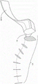
在至少一些实施例中,该凹形安装部分或孔以倾斜的方式被定向或成型,或者相对于患者接口成角度,这样使得当主体的附件被接合到凹形安装部分或孔上或者与其接合时,连接到该主体上的管与患者接口的臂或框架大体对齐。在至少一些实施例中,该管以此方式遵循插管框架臂的形状并且提供以“笔直”方式进入或者与患者接口的歧管或流体连接端口相连接的导管的视觉外观。In at least some embodiments, the female mounting portion or hole is oriented or shaped in an oblique manner, or angled relative to the patient interface, such that when an accessory of the body is engaged on or with the female mounting portion or hole , the tube attached to the body is generally aligned with the arms or frame of the patient interface. In at least some embodiments, the tube in this manner follows the shape of the cannula frame arms and provides the visual appearance of a conduit entering or connecting with a manifold or fluid connection port of a patient interface in a "straight" fashion.
在至少一些实施例中,该安装部分包括突出部,该突出部的形状被设定成接合并且大体填充附件的这些臂之间的空间。In at least some embodiments, the mounting portion includes a protrusion shaped to engage and substantially fill the space between the arms of the accessory.
在至少一些实施例中,该安装部分包括安排成接合附件的至少一个臂的至少一个突出部。在至少一些实施例中,该安装部分包括安排成接合每个臂的突出部。在至少一些实施例中,该一个或多个突出部被安排成利用卡扣接合来接合这些臂。In at least some embodiments, the mounting portion includes at least one protrusion arranged to engage at least one arm of the accessory. In at least some embodiments, the mounting portion includes a protrusion arranged to engage each arm. In at least some embodiments, the one or more protrusions are arranged to engage the arms with a snap fit.
在至少一些实施例中,该安装部分包括安排成接合凸耳的至少一个凹陷或狭槽或孔。在至少一些实施例中,该安装部分包括安排成单独或共同接合每个凸耳的凹陷或狭槽或孔。在至少一些实施例中,该一个或多个凹陷或该一个或多个狭槽或孔被安排成利用卡扣接合来接合这些凸耳。In at least some embodiments, the mounting portion includes at least one recess or slot or hole arranged to engage the lug. In at least some embodiments, the mounting portion includes recesses or slots or holes arranged to engage each lug individually or collectively. In at least some embodiments, the one or more recesses or the one or more slots or holes are arranged to engage the lugs with a snap fit.
在至少一些实施例中,当附件在至少一些实施例中利用卡扣接合来接合安装部分时,该附件向操作者提供感觉反馈。In at least some embodiments, the accessory provides sensory feedback to the operator when the accessory utilizes snap-fit engagement to engage the mounting portion in at least some embodiments.
在至少一些实施例中,当附件上的凸耳在至少一些实施例中利用卡扣接合来接合安装部分上的凹陷时,该附件向操作者提供感觉反馈。In at least some embodiments, the accessory provides sensory feedback to the operator when the lugs on the accessory utilize snap engagement in at least some embodiments to engage the depressions on the mounting portion.
在至少一些实施例中,感觉反馈是听觉反馈、触觉反馈、或两者。In at least some embodiments, the sensory feedback is auditory feedback, haptic feedback, or both.
在至少一些实施例中,当附件在至少一些实施例中利用卡扣接合来接合安装部分时,该附件被安排成发出能够容易听到的声音。In at least some embodiments, the accessory is arranged to emit an easily audible sound when the accessory, in at least some embodiments, utilizes snap-fit engagement to engage the mounting portion.
在至少一些实施例中,当附件在至少一些实施例中利用卡扣接合来接合该安装部分时,该附件被安排成经历能够容易触知的移动或者发出能够容易触知的振动。In at least some embodiments, the accessory is arranged to undergo a tactile movement or emit a tactile vibration when the accessory in at least some embodiments utilizes snap engagement to engage the mounting portion.
在至少一些实施例中,该部件进一步包括用于保持至少一个辅件的至少一个保持器部分。In at least some embodiments, the component further includes at least one retainer portion for retaining at least one accessory.
在至少一些实施例中,该至少一个辅件是至少一个管和/或至少一根缆线和/或至少一条系索。例如,该至少一个辅件可以包括气体管线、气体监测管线(包括但不限于气体取样管线或者用于测量潮气末量的管线)、补水管、供给管、鼻胃管、缆线(包括但不限于电力缆线或传感器缆线(诸如温度探头缆线))、或系索、或其任何两个或更多个的任意组合。In at least some embodiments, the at least one accessory is at least one tube and/or at least one cable and/or at least one lanyard. For example, the at least one accessory may include a gas line, a gas monitoring line (including but not limited to a gas sampling line or a line for measuring end-tidal volume), a rehydration line, a supply line, a nasogastric tube, a cable (including but not limited to a line for measuring end-tidal volume) Limited to power cables or sensor cables (such as temperature probe cables), or lanyards, or any combination of any two or more thereof.
在至少一些实施例中,该至少一个辅件是温度探头缆线。In at least some embodiments, the at least one accessory is a temperature probe cable.
在至少一些实施例中,该至少一个保持器部分是接收该至少一个辅件的环形、大体环形、方形、大体方形、或直线的部分。In at least some embodiments, the at least one retainer portion is an annular, generally annular, square, generally square, or rectilinear portion that receives the at least one accessory.
在至少一些实施例中,该至少一个保持器部分是接收该至少一个辅件的C形部分。In at least some embodiments, the at least one retainer portion is a C-shaped portion that receives the at least one accessory.
在至少一些实施例中,该至少一个保持器部分是接收该至少一个辅件的环形部分。In at least some embodiments, the at least one retainer portion is an annular portion that receives the at least one accessory.
在至少一些实施例中,该至少一个保持器部分是部件的凹陷区域。In at least some embodiments, the at least one retainer portion is a recessed area of the component.
在至少一些实施例中,该至少一个保持器部分从主体延伸。In at least some embodiments, the at least one retainer portion extends from the body.
在至少一些实施例中,该患者接口是鼻罩、口罩、口鼻罩、鼻插管、或全面罩。In at least some embodiments, the patient interface is a nasal mask, mask, oronasal mask, nasal cannula, or full face mask.
在至少一些实施例中,该患者接口是鼻插管。In at least some embodiments, the patient interface is a nasal cannula.
在至少一些实施例中,该患者接口包括一条或多条头部系带或者两条或更多条头部系带。在存在两条或更多条头部系带的至少一些实施例中,该两条或更多条头部系带独自包括单条系带或者两条或更多条系带,其中任一条系带可以是双叉的。In at least some embodiments, the patient interface includes one or more head straps or two or more head straps. In at least some embodiments where there are two or more head straps, the two or more head straps alone comprise a single strap or two or more straps, any one of which is a strap Can be bifurcated.
在至少一些实施例中,该管是医疗呼吸管,包括波纹管或具有螺旋凹陷的表面区域的管。例如,医疗呼吸管由国际标准ISO5367:2000(E)(第四版,2000-06-01)定义。In at least some embodiments, the tube is a medical breathing tube, including a bellows or a tube with a helically recessed surface area. For example, medical breathing tubes are defined by the International Standard ISO 5367:2000(E) (Fourth Edition, 2000-06-01).
在至少一些实施例中,该管是吹气管。In at least some embodiments, the tube is an insufflation tube.
在至少一些实施例中,该管是鼻胃管。In at least some embodiments, the tube is a nasogastric tube.
在至少一些实施例中,该管是传感器缆线。In at least some embodiments, the tube is a sensor cable.
在一些实施例中,该部件包括In some embodiments, the component includes
主体,该主体用于接收至少一个管和/或至少一根缆线(在至少一些实施例中为医疗呼吸回路中的管),该主体包括环形、大体环形、方形、大体方形、或直线的部分,该部分被安排成至少部分地包围或者包围该至少一个管和/或该至少一根缆线的周长,以及a body for receiving at least one tube and/or at least one cable (in at least some embodiments, a tube in a medical breathing circuit), the body comprising annular, generally annular, square, generally square, or rectilinear a portion arranged to at least partially enclose or enclose the perimeter of the at least one tube and/or the at least one cable, and
附件,该附件用于可拆卸地接合患者接口上的与至少一个管和/或至少一根缆线相关联的安装部分,该附件包括一个或两个臂,该一个或两个臂从该主体延伸以便在其间限定空间,每个臂包括成角度部分,该成角度部分延伸到由这些臂限定的空间中或朝向该空间延伸,这样使得这些臂被安排成接合患者接口上的安装部分,并且每个成角度部分利用卡扣接合来接合安装部分上的相应的突出部。an accessory for removably engaging a mounting portion on a patient interface associated with at least one tube and/or at least one cable, the accessory including one or two arms extending from the body extending so as to define a space therebetween, each arm including an angled portion extending into or towards the space defined by the arms such that the arms are arranged to engage a mounting portion on the patient interface, and Each angled portion engages a corresponding protrusion on the mounting portion with a snap fit.
可替代地,该部件包括Alternatively, the component includes
主体,该主体用于接收至少一个管和/或至少一根缆线(诸如医疗呼吸回路中的管),该主体包括环形、大体环形、方形、大体方形、或直线的部分,该部分被安排成至少部分地包围或者包围该至少一个管和/或该至少一根缆线的周长,以及a body for receiving at least one tube and/or at least one cable (such as a tube in a medical breathing circuit), the body comprising an annular, generally annular, square, generally square, or rectilinear portion arranged to at least partially surround or enclose the perimeter of the at least one tube and/or the at least one cable, and
附件,该附件用于可拆卸地接合患者接口上的与至少一个管和/或至少一根缆线相关联的安装部分,该附件包括至少一个臂或可替代地多个臂,该至少一个臂或可替代地多个臂从该主体延伸以便在其间限定空间,每个臂包括成角度部分或凸耳部分,该成角度部分或凸耳部分从这些臂向外延伸或远离这些臂延伸,这样使得这些臂被安排成接合患者接口上的安装部分,并且每个成角度部分或凸耳部分利用卡扣接合来接合安装部分上的相应的突出部。在实施例中,该附件包括两个臂。an accessory for removably engaging a mounting portion on a patient interface associated with at least one tube and/or at least one cable, the accessory comprising at least one arm or alternatively a plurality of arms, the at least one arm or alternatively a plurality of arms extending from the body so as to define a space therebetween, each arm comprising an angled portion or lug portion extending outwardly or away from the arms such that Such that the arms are arranged to engage a mounting portion on the patient interface, and each angled portion or lug portion engages a corresponding protrusion on the mounting portion with a snap fit. In an embodiment, the accessory includes two arms.
在一些实施例中,该部件包括In some embodiments, the component includes
主体,该主体用于接收至少一个管和/或至少一根缆线(在至少一些实施例中为医疗呼吸回路中的管),该主体包括环形、大体环形、方形、大体方形、或直线的部分,该部分被安排成至少部分地包围或者包围该至少一个管和/或该至少一根缆线的周长,以及A body for receiving at least one tube and/or at least one cable (in at least some embodiments, a tube in a medical breathing circuit), the body comprising annular, generally annular, square, generally square, or rectilinear a portion arranged to at least partially surround or enclose the perimeter of the at least one tube and/or the at least one cable, and
附件,该附件用于可拆卸地接合患者接口上的与至少一个管和/或至少一根缆线相关联的安装部分,该附件包括一个或两个臂,该一个或两个臂从该主体延伸以便在其间限定空间,每个臂包括突出部或凸耳,该突出部或凸耳延伸到由这些臂限定的空间中或朝向该空间延伸,这样使得这些臂被安排成接合患者接口上的安装部分,并且每个突出部或凸耳利用卡扣接合来接合安装部分上的相应的凹陷。an accessory for removably engaging a mounting portion on a patient interface associated with at least one tube and/or at least one cable, the accessory including one or two arms extending from the body Extending so as to define a space therebetween, each arm includes a protrusion or lug that extends into or toward the space defined by the arms such that the arms are arranged to engage a nipple on the patient interface the mounting portion, and each protrusion or lug engages a corresponding recess on the mounting portion with a snap fit.
可替代地,该部件包括Alternatively, the component includes
主体,该主体用于接收至少一个管和/或至少一根缆线(诸如医疗呼吸回路中的管),该主体包括环形、大体环形、方形、大体方形、或直线的部分,该部分被安排成至少部分地包围或者包围该至少一个管和/或该至少一根缆线的周长,以及a body for receiving at least one tube and/or at least one cable (such as a tube in a medical breathing circuit), the body comprising an annular, generally annular, square, generally square, or rectilinear portion arranged to at least partially surround or enclose the perimeter of the at least one tube and/or the at least one cable, and
附件,该附件用于可拆卸地接合患者接口上的与至少一个管和/或至少一根缆线相关联的安装部分,该附件包括至少一个臂、可替代地多个臂,该至少一个臂或可替代地多个臂从该主体延伸以便在其间限定空间,每个臂包括突出部或凸耳,该突出部或凸耳远离这些臂延伸或从这些臂向外延伸,这样使得这些臂被安排成接合患者接口上的安装部分,并且每个突出部或凸耳利用卡扣接合来接合安装部分上的相应的凹陷。在实施例中,该附件包括两个臂。an accessory for removably engaging a mounting portion on a patient interface associated with at least one tube and/or at least one cable, the accessory comprising at least one arm, alternatively a plurality of arms, the at least one arm Or alternatively a plurality of arms extend from the body so as to define a space therebetween, each arm including a protrusion or lug extending away from the arms or extending outwardly from the arms such that the arms are Arranged to engage a mounting portion on the patient interface, and each protrusion or lug engages a corresponding recess on the mounting portion with a snap fit. In an embodiment, the accessory includes two arms.
在第二方面中,本披露广义地涉及管,诸如用于医疗呼吸回路的管,该管(如在此所描述)被联接到如在此所描述的部件上,该部件任选地被可拆卸地接合到如在此所描述的安装部分上,该安装部分能够可拆卸地附接到医疗呼吸回路中的患者接口上。In a second aspect, the present disclosure broadly relates to tubing, such as tubing for a medical breathing circuit, the tubing (as described herein) being coupled to a component as described herein, the component optionally being configurable Removably engages a mounting portion as described herein that is removably attachable to a patient interface in a medical breathing circuit.
在第三方面中,本披露广义地涉及患者接口(如在此所描述),诸如用于医疗呼吸回路的患者接口,该患者接口包括安装部分(诸如在此所描述的那些),该安装部分与患者接口成整体或被可拆卸地附接到该患者接口上;以及如在此所描述的部件,该部件被可拆卸地接合到该安装部分上。In a third aspect, the present disclosure broadly relates to a patient interface (as described herein), such as a patient interface for a medical breathing circuit, comprising a mounting portion (such as those described herein), the mounting portion integrally or removably attached to the patient interface; and a component as described herein removably engaged to the mounting portion.
在第四方面中,本披露广义地涉及套件,该套件包括如在此所描述的部件以及以下各项中的任何两个或更多个:In a fourth aspect, the present disclosure broadly relates to kits comprising components as described herein and any two or more of:
如在此所描述的患者接口,该患者接口任选地包括如在此所描述的一体式安装部分,A patient interface as described herein optionally comprising an integral mounting portion as described herein,
如在此所描述的安装部分,以及the installation section as described here, and
组装和/或使用说明书。Assembly and/or Instructions for Use.
以上称为“夹具”的部件的不同方面和实施例可以被提供用于关于将物件(例如,呼吸管)紧固或保持或支撑到安装部分上,例如,患者接口(任选地呈鼻插管的形式)可以包括用于接收如在此所描述的这种部件的这种“夹具”。还应了解,这种“夹具”和分别描述的安装部分可以结合鼻插管患者接口的侧臂来提供。Various aspects and embodiments of the components referred to above as "clamps" may be provided for securing or retaining or supporting an item (eg, a breathing tube) to a mounting portion, eg, a patient interface (optionally in the form of a nasal plug) tube form) may include such a "clamp" for receiving such a component as described herein. It will also be appreciated that such a "clamp" and separately described mounting portion may be provided in conjunction with the side arm of the nasal cannula patient interface.
另外,以上关于第一至第四方面中的每一个所描述的“夹具”可以整合或组合以下关于患者接口或用于组装患者接口的零部件所描述的其他方面中的一个或多个来提供。Additionally, the "clamps" described above in relation to each of the first to fourth aspects may be provided in conjunction with or in combination with one or more of the other aspects described below in relation to the patient interface or components used to assemble the patient interface .
本披露的目的是提供诸如用于与作为医疗呼吸回路的一部分的患者接口一起使用的连接器,该连接器至少在一定程度上将朝着改进以上内容的方向发展或者将至少为公众或医疗行业提供有用的选择。It is an object of the present disclosure to provide a connector, such as for use with a patient interface as part of a medical breathing circuit, that will at least in part be directed towards improving the above or at least for the public or the medical industry Offers useful options.
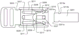
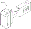
在第四方面中,本披露广义地涉及连接器(在此为“带扣”),包括:In a fourth aspect, the present disclosure relates broadly to connectors (herein "buckles"), including:
第一连接器零件;a first connector part;
第二连接器零件;second connector part;
锁销,该锁销用于将第一连接器零件和第二连接器零件紧固在一起;a locking pin for securing the first connector part and the second connector part together;
滑动件,该滑动件相对于第一连接器零件和/或第二连接器零件是在以下位置之间可移动的:A slider movable relative to the first connector part and/or the second connector part between:
紧固位置,在该紧固位置中该锁销基本上无法移动并且无法使该第一连接器零件从该第二连接器零件释放;以及a fastened position in which the locking pin is substantially immobile and incapable of releasing the first connector part from the second connector part; and
自由位置,在该自由位置中该锁销能够移动以便使该第一连接器零件从该第二连接器零件释放。A free position in which the locking pin can move to release the first connector part from the second connector part.
应当理解,以下实施例中的任一个可以单独或以任何两个或更多个的任意组合涉及以上和以下所描述的披露的各方面中的任一个。It should be understood that any of the following embodiments may relate to any of the various aspects of the disclosure described above and below, alone or in any combination of any two or more.
在一些实施例中,该连接器进一步包括用于朝向紧固位置推动滑动件的偏置装置。In some embodiments, the connector further includes biasing means for urging the slider toward the secured position.
在一些实施例中,该偏置装置包括弹性支腿。In some embodiments, the biasing means includes resilient legs.
在一些实施例中,该偏置装置包括一对弹性支腿。可替代地,这些支腿随着该滑动件朝向自由位置移动而远离彼此移动。可替代地,这些支腿可以随着该滑动件朝向自由位置移动而朝向彼此移动。In some embodiments, the biasing means includes a pair of resilient legs. Alternatively, the legs move away from each other as the slider moves towards the free position. Alternatively, the legs may move towards each other as the slider moves towards the free position.
在一些实施例中,该偏置装置和该锁销一体形成在一起。In some embodiments, the biasing device and the locking pin are integrally formed.
在一些实施例中,该锁销包括弹性臂。任选地,该弹性臂被朝向与第一连接器零件的接合偏置。In some embodiments, the locking pin includes a resilient arm. Optionally, the resilient arm is biased towards engagement with the first connector part.
在一些实施例中,该锁销包括一对弹性臂。任选地,这对弹性臂被朝向与第一连接器零件的接合偏置。In some embodiments, the locking pin includes a pair of resilient arms. Optionally, the pair of resilient arms are biased towards engagement with the first connector part.
在一些实施例中,这对弹性臂被间隔开并且朝向彼此偏置。In some embodiments, the pair of resilient arms are spaced apart and biased toward each other.
在一些实施例中,该弹性臂或每个弹性臂包括用于与第一连接器零件的互补凹口接合的突出部。In some embodiments, the or each resilient arm includes a protrusion for engaging a complementary recess of the first connector part.
在一些实施例中,该滑动件包括用于与偏置装置接合的凸耳。任选地,该凸耳包括向外渐缩的表面。In some embodiments, the slider includes lugs for engagement with the biasing means. Optionally, the lugs include outwardly tapered surfaces.
在一些实施例中,该滑动件包括突出部,该突出部用于与锁销接合以便基本上抑制第一连接器零件的移动并且使该第一连接器零件无法从第二连接器零件释放。In some embodiments, the slider includes a protrusion for engaging the latch to substantially inhibit movement of the first connector part and to prevent release of the first connector part from the second connector part.
在一些实施例中,该滑动件包括两个突出部,这两个突出部用于与锁销接合以便基本上抑制第一连接器零件的移动并且使该第一连接器零件无法从第二连接器零件释放。In some embodiments, the slider includes two protrusions for engaging the locking pin so as to substantially inhibit movement of the first connector part and prevent the first connector part from being connected from the second device parts release.
在一些实施例中,该滑动件包括用于将该滑动件和第二连接器零件定位在紧固构型中的止动件。In some embodiments, the slider includes a stop for positioning the slider and the second connector part in the secured configuration.
在一些实施例中,该滑动件包括套筒。In some embodiments, the slider includes a sleeve.
在一些实施例中,该滑动件使得能够进行单手操作以便从紧固位置移动到自由位置。In some embodiments, the slider enables one-handed operation to move from the secured position to the free position.
在一些实施例中,该第一连接器零件包括凹口。In some embodiments, the first connector part includes a notch.
在一些实施例中,该第一连接器零件包括一对凹口。In some embodiments, the first connector part includes a pair of notches.
在一些实施例中,该第一连接器零件是基本上平面的部件。In some embodiments, the first connector part is a substantially planar part.
在一些实施例中,该第一连接器零件是大体刚性的部件。In some embodiments, the first connector part is a substantially rigid component.
在一些实施例中,该第一连接器零件包括夹具。In some embodiments, the first connector part includes a clamp.
在一些实施例中,该第一连接器零件位于患者接口上。In some embodiments, the first connector part is located on the patient interface.
在一些实施例中,该第一连接器零件被附接到患者接口或患者接口的一部分上、或与其一体形成、或者作为该患者接口的一部分。In some embodiments, the first connector part is attached to, integrally formed with, or part of the patient interface or a portion of the patient interface.
在一些实施例中,该第一连接器零件被附接到患者接口的臂的一部分上,或与其一体形成,或作为该患者接口的臂的一部分。例如,臂可以是从鼻插管的中心歧管区域或者一个鼻叉头或一对鼻叉头向外延伸的侧臂。In some embodiments, the first connector part is attached to, or integrally formed with, a portion of the arm of the patient interface, or as part of the arm of the patient interface. For example, the arms may be lateral arms extending outwardly from the central manifold region of the nasal cannula or a nasal prong or a pair of nasal prongs.
在一些实施例中,该第二连接器零件包括用于对偏置装置进行定位的定位特征部。In some embodiments, the second connector part includes locating features for locating the biasing means.
在一些实施例中,该第二连接器零件包括用于引导第一连接器零件的引导特征部。In some embodiments, the second connector part includes guide features for guiding the first connector part.
在一些实施例中,该第二连接器零件具有用于引导滑动件的引导特征部。In some embodiments, the second connector part has guide features for guiding the slider.
在一些实施例中,该第二连接器零件包括用于承载锁销和/或偏置装置的载体。In some embodiments, the second connector part includes a carrier for carrying the detent and/or biasing means.
在一些实施例中,该载体形成有狭槽,并且头帽的头部系带具有开口,该狭槽和该开口被安排用于接收第一连接器零件。In some embodiments, the carrier is formed with a slot and the head strap of the headgear has an opening, the slot and the opening being arranged to receive the first connector part.
在第六方面中,本披露广义地涉及连接器,包括:In a sixth aspect, the present disclosure relates broadly to connectors, including:
第一连接器零件;a first connector part;
锁销,该锁销用于将第一连接器零件和第二连接器零件紧固在一起;a locking pin for securing the first connector part and the second connector part together;
滑动件,该滑动件相对于第一连接器零件是在以下位置之间可移动的:a slider movable relative to the first connector part between:
紧固位置,在该紧固位置中该锁销基本上无法移动并且无法使该第一连接器零件从该第二连接器零件释放;以及a fastened position in which the locking pin is substantially immobile and incapable of releasing the first connector part from the second connector part; and
自由位置,在该自由位置中该锁销能够移动以便使该第一连接器零件从该第二连接器零件释放。A free position in which the locking pin can move to release the first connector part from the second connector part.
在第七方面中,本披露广义地涉及用于医疗呼吸回路的患者接口,该患者接口包括第二方面的连接器。In a seventh aspect, the present disclosure broadly relates to a patient interface for a medical breathing circuit, the patient interface comprising the connector of the second aspect.
第六方面和/或第七方面可以包括以上关于第七方面所描述的特征部中的一个或多个。The sixth and/or seventh aspects may include one or more of the features described above with respect to the seventh aspect.
以上称为“带扣”的部件的不同方面和实施例可以被提供用于与物件的紧固或保持或支撑关联使用(例如,将头帽或头部系带端紧固或保持或支撑到患者接口诸如鼻插管的侧臂端)。然而,还应了解,以上所描述的“带扣”可以用于在患者接口的其他设施之间提供可释放的连接点。还应了解,这种“带扣”可以结合鼻插管患者接口的侧臂或者系带的用于头帽与患者接口连接的头帽部分的端部来提供。Various aspects and embodiments of the components referred to above as "buckles" may be provided for use in connection with the securing or retaining or supporting of an article (eg, securing or retaining or supporting a headgear or head strap end to patient interface such as the side arm end of a nasal cannula). However, it should also be appreciated that the "buckles" described above may be used to provide releasable connection points between other facilities of the patient interface. It will also be appreciated that such a "buckle" may be provided in conjunction with the side arms of the nasal cannula patient interface or the end of the headgear portion of the strap for connection of the headgear to the patient interface.
在另一个实施例中,如上所描述的“夹具”可以在用于鼻插管或鼻插管的框架上时找到特定应用,从而允许相对容易地连接或附接以及断开连接或移除头帽,这是因为由“夹具”保持或支撑的导管或管可以被保持或支撑在避免与头帽缠结的适当位置、地点或取向中。进一步地,如在此所描述的“带扣”还可以与患者接口(诸如鼻插管)的臂的端部连接或断开连接,这是因为任何管或导管被有效地整齐地收拢并支撑在避免与头帽缠结并且不妨碍用户试图对可释放的带扣进行定位和操作的适当位置或地点中。In another embodiment, a "clamp" as described above may find particular application when used on a nasal cannula or a frame for a nasal cannula, allowing relatively easy connection or attachment and disconnection or removal of the head cap, because the catheter or tube held or supported by the "clamp" can be held or supported in a proper position, location or orientation that avoids tangling with the headgear. Further, a "buckle" as described herein can also be connected or disconnected from the end of an arm of a patient interface, such as a nasal cannula, since any tube or conduit is effectively neatly tucked and supported In a suitable location or location that avoids tangling with the headgear and does not interfere with the user's attempts to position and operate the releasable buckle.
另外,以上关于第五方面至第七方面中的每一个所描述的“带扣”可以整合或组合以下关于患者接口或用于组装患者接口的零部件所描述的其他方面中的一个或多个来提供。Additionally, the "buckles" described above with respect to each of the fifth to seventh aspects may integrate or combine one or more of the other aspects described below with respect to the patient interface or components used to assemble the patient interface to provide.
在许多环境中,气体源相对于患者可以被定位在有限数目的位置中。因此,从气体源延伸到患者接口的导管可以位于不方便的或不舒适的位置中,诸如位于患者胸部或颈部上。另外,在一些情况下,如果导管相对于至少患者接口并未被最佳地定向,可能会损害所递送治疗的方便性或有效性。例如,导管上的过度推动力或扭转力可能会迫使患者接口远离患者,会致使导管从患者接口或气体源移开,或者会致使气体源从桌子或其他支架落下。In many environments, the gas source may be positioned in a limited number of locations relative to the patient. Accordingly, the conduit extending from the gas source to the patient interface may be located in an inconvenient or uncomfortable location, such as on the patient's chest or neck. Additionally, in some cases, if the catheter is not optimally oriented relative to at least the patient interface, the convenience or effectiveness of the therapy delivered may be compromised. For example, excessive pushing or twisting force on the catheter may force the patient interface away from the patient, cause the catheter to move away from the patient interface or gas source, or cause the gas source to fall off a table or other stand.
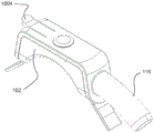
在此所披露的实施例中的至少一个的某些特征、方面以及优点应用于第八方面并且包括以下实现:患者接口可以包括适配成接收来自气体源的气体的可旋转组件(在此为“转动歧管”)。Certain features, aspects, and advantages of at least one of the embodiments disclosed herein apply to the eighth aspect and include implementations in which the patient interface may include a rotatable assembly (here a rotatable assembly adapted to receive gas from a gas source) "Turn Manifold").
在一些实施例中,患者接口可以包括适配成接收气体的歧管,该歧管被可旋转地紧固到适配成将气体引导至用户的框架上。In some embodiments, the patient interface may include a manifold adapted to receive gas that is rotatably secured to a frame adapted to direct gas to a user.
在一些实施例中,该歧管可以仅在某些旋转取向上将气体传递到框架,和/或可以在相对于该框架的某些旋转取向上被旋转地锁定在适当位置中。In some embodiments, the manifold may deliver gas to the frame only in certain rotational orientations, and/or may be rotationally locked in place in certain rotational orientations relative to the frame.
在一些实施例中,如果歧管相对于框架被旋转地锁定在适当位置中,释放机构可以用于“解锁”患者接口并且允许相对于该框架进一步旋转移动该歧管。该可旋转组件随后可以允许链接到接口上的导管相对于该接口和/或气体源定位在多个取向上,这可以改善所递送呼吸疗法的方便性和/或有效性。In some embodiments, if the manifold is rotationally locked in position relative to the frame, a release mechanism may be used to "unlock" the patient interface and allow further rotational movement of the manifold relative to the frame. The rotatable assembly may then allow catheters linked to the interface to be positioned in multiple orientations relative to the interface and/or gas source, which may improve the convenience and/or effectiveness of the respiratory therapy delivered.
因此,根据在此所披露的实施例中的至少一个的某些特征、方面以及优点,披露了一种患者接口。例如,在第九方面中,本披露涉及可以包括鼻插管的患者接口。该患者接口可以包括适配成定位在用户面部上的框架。该框架可以包括适配成将气体引导至用户的气体室。该患者接口还可以包括歧管,该歧管被可旋转地紧固到框架上并且被适配成接收来自气体源的气体。该歧管可以被可旋转地紧固到框架上,其方式为使得歧管与框架之间的旋转或旋转运动范围被限制,例如,限制为小于360旋转度。Accordingly, in accordance with certain features, aspects, and advantages of at least one of the embodiments disclosed herein, a patient interface is disclosed. For example, in a ninth aspect, the present disclosure relates to a patient interface that may include a nasal cannula. The patient interface may include a frame adapted to be positioned on the user's face. The frame may include a gas chamber adapted to direct gas to the user. The patient interface may also include a manifold rotatably secured to the frame and adapted to receive gas from a gas source. The manifold may be rotatably fastened to the frame in a manner such that the range of rotational or rotational motion between the manifold and the frame is limited, eg, to less than 360 degrees of rotation.
在一些实施例中,在歧管与框架之间的旋转运动范围可以被限制为约180度。In some embodiments, the range of rotational motion between the manifold and the frame may be limited to about 180 degrees.
在一些实施例中,该框架可以包括限制旋转运动(例如,歧管相对于框架的旋转运动)范围的止动件。In some embodiments, the frame may include stops that limit the range of rotational movement (eg, rotational movement of the manifold relative to the frame).
在一些实施例中,该歧管可以包括轴结构,该歧管可以相对于框架围绕该轴结构枢转。在一些这类实施例中,该轴结构可以突出穿过框架中的孔。在替代实施例中,该框架可以包括突出穿过歧管中的孔的轴结构。In some embodiments, the manifold can include a shaft structure about which the manifold can pivot relative to the frame. In some such embodiments, the shaft structure may protrude through holes in the frame. In alternative embodiments, the frame may include shaft structures that protrude through holes in the manifold.
另外,根据在此所披露的实施例中的至少一个的某些特征、方面以及优点,披露了患者接口。在第十方面中,患者接口可以包括鼻插管。该患者接口可以包括适配成定位在用户面部上的框架。该框架可以包括适配成将气体引导至用户的气体室。该患者接口还可以包括歧管,该歧管被可旋转地紧固到框架上并且被适配成接收来自气体源的气体。该患者接口可以被构造成使得歧管相对于框架的非旋转运动被限制。Additionally, in accordance with certain features, aspects, and advantages of at least one of the embodiments disclosed herein, a patient interface is disclosed. In a tenth aspect, the patient interface may comprise a nasal cannula. The patient interface may include a frame adapted to be positioned on the user's face. The frame may include a gas chamber adapted to direct gas to the user. The patient interface may also include a manifold rotatably secured to the frame and adapted to receive gas from a gas source. The patient interface may be configured such that non-rotational movement of the manifold relative to the frame is restricted.
在一些实施例中,该框架进一步包括柱,该柱被适配成限制歧管相对于框架的非旋转运动。In some embodiments, the frame further includes a post adapted to limit non-rotational movement of the manifold relative to the frame.
在一些实施例中,歧管相对于框架的非旋转运动的范围仅在一些旋转取向上被限制。In some embodiments, the range of non-rotational motion of the manifold relative to the frame is limited only in some rotational orientations.
另外,根据在此所披露的实施例中的至少一个的某些特征、方面以及优点,披露了患者接口。该患者接口可以包括鼻插管。在第十一方面中,患者接口可以包括适配成定位在用户面部上的框架。该框架可以包括适配成将气体引导至用户的气体室。该患者接口还可以包括歧管,该歧管被可旋转地紧固到框架上并且被适配成接收来自气体源的气体。该患者接口可以被构造成使得不容许歧管相对于框架在至少一个旋转取向上进一步旋转。该患者接口可以被构造成在已经实现某一旋转取向之后锁定歧管相对于框架的旋转取向。该患者接口可以包括释放机构,该释放机构被适配成在一般不容许歧管相对于框架旋转时容许该歧管相对于该框架进行旋转运动。该释放机构可以解锁歧管相对于框架的固定旋转取向。在解锁之后,该患者接口还可以再次容许歧管相对于框架旋转。Additionally, in accordance with certain features, aspects, and advantages of at least one of the embodiments disclosed herein, a patient interface is disclosed. The patient interface may include a nasal cannula. In an eleventh aspect, the patient interface may include a frame adapted to be positioned on the user's face. The frame may include a gas chamber adapted to direct gas to the user. The patient interface may also include a manifold rotatably secured to the frame and adapted to receive gas from a gas source. The patient interface may be configured such that further rotation of the manifold relative to the frame in at least one rotational orientation is not permitted. The patient interface may be configured to lock the rotational orientation of the manifold relative to the frame after a rotational orientation has been achieved. The patient interface may include a release mechanism adapted to allow rotational movement of the manifold relative to the frame when rotation of the manifold relative to the frame is generally not permitted. The release mechanism can unlock the fixed rotational orientation of the manifold relative to the frame. After unlocking, the patient interface may again allow the manifold to rotate relative to the frame.
在一些实施例中,该释放机构可以包括手动可按压的按钮。可以按下该按钮以便解锁固定旋转取向。该按钮可以定位在框架上。在一些替代实施例中,该按钮可以定位在框架内。In some embodiments, the release mechanism may comprise a manually depressable button. This button can be pressed to unlock the fixed rotational orientation. The button can be positioned on the frame. In some alternative embodiments, the button may be positioned within the frame.
在一些实施例中,该歧管可以包括凸台,该凸台被适配成在该框架的互补轨道中可旋转地移动,并且该轨道可以包括可以限制凸台运动的滞留区域。In some embodiments, the manifold may include bosses adapted to move rotatably in complementary tracks of the frame, and the tracks may include retention areas that may limit movement of the bosses.
另外,根据在此所披露的实施例中的至少一个的某些特征、方面以及优点,披露了患者接口。该患者接口可以包括以上或本披露中别处所披露的特征部的组合。Additionally, in accordance with certain features, aspects, and advantages of at least one of the embodiments disclosed herein, a patient interface is disclosed. The patient interface may include a combination of features disclosed above or elsewhere in this disclosure.
在一些实施例中,以上或本披露中别处所披露的患者接口可以包括歧管,该歧管包括适配成在框架的互补轨道中可旋转地移动的凸台。In some embodiments, the patient interface disclosed above or elsewhere in this disclosure may include a manifold including bosses adapted to move rotatably in complementary tracks of the frame.
在一些实施例中,以上或本披露中别处所披露的患者接口可以包括被永久地可旋转地紧固到框架上的歧管。In some embodiments, the patient interface disclosed above or elsewhere in this disclosure may include a manifold that is permanently rotatably fastened to the frame.
在一些实施例中,以上或本披露中别处所披露的患者接口可以包括歧管,该歧管被构造成与框架协作来仅在一些或某些取向(例如,例如歧管相对于框架的旋转或旋转取向)上将气体引导到气体室。In some embodiments, the patient interface disclosed above or elsewhere in this disclosure may include a manifold configured to cooperate with the frame to operate only in some or some orientations (eg, such as rotation of the manifold relative to the frame) or rotational orientation) to guide the gas into the gas chamber.
在一些实施例中,以上或本披露中别处所披露的患者接口可以包括框架,该框架包括相对刚性区段和相对挠性区段。在一些这类实施例中,框架的相对挠性区段可以被包覆模制到该框架的相对刚性区段的面部接触部分上。在一些这类实施例中,该患者接口可以包括适配成插入用户的一个鼻孔或两个鼻孔中的鼻递送元件。该鼻递送元件可以从框架的相对挠性区段延伸。In some embodiments, the patient interface disclosed above or elsewhere in this disclosure can include a frame that includes a relatively rigid section and a relatively flexible section. In some such embodiments, the relatively flexible section of the frame may be overmolded onto the face-contacting portion of the relatively rigid section of the frame. In some such embodiments, the patient interface may include a nasal delivery element adapted to be inserted into one or both nostrils of the user. The nasal delivery element may extend from opposing flexible sections of the frame.
在一些实施例中,以上或本披露中别处所披露的患者接口可以包括适配成插入用户的鼻孔中的鼻递送元件。该鼻递送元件可以从框架延伸。In some embodiments, the patient interface disclosed above or elsewhere in this disclosure may include a nasal delivery element adapted to be inserted into a user's nostrils. The nasal delivery element can extend from the frame.
在第十二方面中,本披露广义地涉及患者接口,包括:In a twelfth aspect, the present disclosure relates broadly to patient interfaces, including:
框架区段,该框架区段被适配成定位在用户面部上,该框架区段包括适配成将气体引导至该用户的气体室以及从该气体室延伸的鼻递送元件,该鼻递送元件被适配成定位在该用户的鼻孔中;以及歧管,该歧管被可旋转地紧固到框架区段上,该歧管被构造成相对于框架区段旋转,该歧管包括轴结构,在歧管与框架区段之间的旋转运动可以围绕该轴结构发生。a frame section adapted to be positioned on the face of a user, the frame section including a gas chamber adapted to direct gas to the user and a nasal delivery element extending from the gas chamber, the nasal delivery element adapted to be positioned in the user's nostrils; and a manifold rotatably secured to the frame section, the manifold configured to rotate relative to the frame section, the manifold including a shaft structure , the rotational movement between the manifold and the frame segment can occur about the shaft structure.
在一些实施例中,该轴结构突出穿过框架区段中的孔。In some embodiments, the shaft structure protrudes through a hole in the frame section.
在一些实施例中,该歧管被可旋转地紧固到框架区段上,其方式为使得歧管与框架区段之间的旋转运动范围被限制。In some embodiments, the manifold is rotatably secured to the frame section in a manner such that the range of rotational motion between the manifold and the frame section is limited.
在一些实施例中,该框架区段包括限制旋转运动范围的止动件。In some embodiments, the frame section includes stops that limit the range of rotational motion.
在一些实施例中,该患者接口进一步包括从气体室延伸的鼻递送元件,该鼻递送元件被适配成定位在用户的鼻孔中。In some embodiments, the patient interface further includes a nasal delivery element extending from the gas chamber, the nasal delivery element adapted to be positioned in the nostrils of the user.
在一些实施例中,该框架区段进一步包括轨道,该轨道被构造成引导歧管相对于框架区段旋转。In some embodiments, the frame section further includes a track configured to guide rotation of the manifold relative to the frame section.
在一些实施例中,该接口进一步包括保持机构,该保持机构被布置在框架区段上,该保持机构被构造成将歧管保持在操作位置中,这样使得在歧管与气体室之间形成气动密封。In some embodiments, the interface further includes a retention mechanism disposed on the frame section, the retention mechanism configured to retain the manifold in the operative position such that a formation is formed between the manifold and the gas chamber Pneumatic seal.
在一些实施例中,该保持机构是从框架区段向外延伸的柱,该柱被构造成当歧管处于操作位置中时将该歧管保持在框架区段与柱之间。In some embodiments, the retaining mechanism is a post extending outwardly from the frame section, the post being configured to retain the manifold between the frame section and the post when the manifold is in the operating position.
在一些实施例中,该患者接口包括释放机构,该释放机构被构造成将歧管从操作位置释放,这样使得该歧管可以相对于框架区段旋转。In some embodiments, the patient interface includes a release mechanism configured to release the manifold from the operative position such that the manifold can be rotated relative to the frame section.
在一些实施例中,该释放机构包括按钮,该按钮被布置在歧管上,该按钮包括凸台部分,该凸台部分被构造成在歧管旋转时与轨道的大部分接合并且在该轨道的大部分内移动。In some embodiments, the release mechanism includes a button disposed on the manifold, the button including a boss portion configured to engage a substantial portion of the track when the manifold rotates Most of them move within.
在一些实施例中,该轨道包括定位在轨道的端部处的一个或多个滞留区域,所构造的凸台接合这些滞留区域以便将歧管锁定在操作位置中。In some embodiments, the track includes one or more stagnant regions positioned at ends of the track, the bosses being configured to engage the stagnant regions to lock the manifold in the operative position.
在一些实施例中,该释放机构包括释放主体,该释放主体是在歧管内的凹陷内可移动的,该释放主体能够从未偏置位置移动到已偏置位置,当歧管处于操作位置中时,该释放主体处于未偏置位置中。In some embodiments, the release mechanism includes a release body movable within a recess in the manifold, the release body being movable from an unbiased position to a biased position when the manifold is in the operative position , the release body is in an unbiased position.
在一些实施例中,该释放主体包括一个或多个侧臂,该凹陷包括一个或多个端部区域,该一个或多个端部区域的形状被设定成对应于该一个或多个侧臂,这些侧臂被构造成移动到端部区域中以便使凸台部分从滞留区域释放并且允许歧管旋转。In some embodiments, the release body includes one or more side arms and the recess includes one or more end regions that are shaped to correspond to the one or more sides Arms, the side arms are configured to move into the end region to release the boss portion from the retention region and allow the manifold to rotate.
在一些实施例中,这些侧臂被构造成向外展开以便使凸台部分从滞留区域释放。In some embodiments, the side arms are configured to flare out to release the boss portion from the retention area.
在一些实施例中,这些侧臂被构造成向内展开以便使凸台部分从滞留区域释放。In some embodiments, the side arms are configured to flare inward to release the boss portion from the retention area.
在一些实施例中,该患者接口进一步包括从气体室延伸的至少一个鼻递送元件,每个鼻递送元件被适配成定位在用户的鼻孔中。In some embodiments, the patient interface further includes at least one nasal delivery element extending from the gas chamber, each nasal delivery element adapted to be positioned in the nostrils of the user.
在一些实施例中,该至少一个鼻递送元件包括两个鼻递送元件。In some embodiments, the at least one nasal delivery element includes two nasal delivery elements.
在第十三方面中,本披露广义地涉及患者接口,包括:In a thirteenth aspect, the present disclosure relates broadly to patient interfaces, including:
框架区段,该框架区段被适配成定位在用户面部上,该框架区段包括适配成将气体引导至用户的气体室;a frame section adapted to be positioned on a user's face, the frame section including a gas chamber adapted to direct gas to the user;
歧管,该歧管是相对于该框架区段可旋转的并且被适配成接收来自气体源的气体;以及a manifold that is rotatable relative to the frame section and adapted to receive gas from a gas source; and
保持机构,该保持机构被布置在框架区段上,并且该保持机构被构造成限制歧管相对于框架区段的非旋转运动。A retention mechanism disposed on the frame segment and configured to limit non-rotational movement of the manifold relative to the frame segment.
在一些实施例中,该保持机构包括适配成保持歧管的柱。In some embodiments, the retention mechanism includes a post adapted to retain the manifold.
在一些实施例中,该保持机构仅在一些旋转取向上限制歧管相对于框架区段的非旋转运动。In some embodiments, the retention mechanism limits non-rotational movement of the manifold relative to the frame section only in some rotational orientations.
在一些实施例中,该保持机构仅在一些旋转取向上密封在歧管与气体室之间延伸的气体通路。In some embodiments, the retention mechanism seals the gas passageway extending between the manifold and the gas chamber only in some rotational orientations.
在一些实施例中,该患者接口进一步包括从气体室延伸的鼻递送元件,该鼻递送元件被适配成定位在用户的鼻孔中。In some embodiments, the patient interface further includes a nasal delivery element extending from the gas chamber, the nasal delivery element adapted to be positioned in the nostrils of the user.
在一些实施例中,该歧管被可旋转地紧固到框架区段上。In some embodiments, the manifold is rotatably fastened to the frame segment.
在一些实施例中,该保持机构被布置在框架区段上。In some embodiments, the retention mechanism is arranged on the frame section.
在一些实施例中,该保持机构与框架区段一体形成。In some embodiments, the retention mechanism is integrally formed with the frame section.
在一些实施例中,该保持机构被布置在歧管上。In some embodiments, the retention mechanism is disposed on the manifold.
在一些实施例中,该保持机构与歧管一体形成。In some embodiments, the retention mechanism is integrally formed with the manifold.
在一些实施例中,该保持机构包括布置在歧管上的第一保持特征部以及布置在框架区段上的第二保持特征部。In some embodiments, the retention mechanism includes a first retention feature disposed on the manifold and a second retention feature disposed on the frame segment.
在一些实施例中,该第一保持特征部包括第一钩,该第一钩具有总体竖直延伸部分以及在朝向歧管的方向上从该总体竖直延伸部分延伸的总体水平延伸部分,并且该第二保持特征部包括第二钩,该第二钩具有总体竖直延伸部分以及在远离歧管的方向上从该总体竖直延伸部分延伸的总体水平延伸部分。In some embodiments, the first retention feature includes a first hook having a generally vertical extension and a generally horizontal extension extending from the generally vertical extension in a direction toward the manifold, and The second retention feature includes a second hook having a generally vertically extending portion and a generally horizontally extending portion extending from the generally vertically extending portion in a direction away from the manifold.
在一些实施例中,该第一保持特征部包括第一钩,该第一钩具有总体竖直延伸部分以及在远离歧管的方向上从该总体延伸部分延伸的总体水平延伸部分,并且该第二保持特征部包括第二钩,该第二钩具有总体竖直延伸部分以及在朝向歧管的方向上从该总体竖直延伸部分延伸的总体水平延伸部分。In some embodiments, the first retention feature includes a first hook having a generally vertical extension and a generally horizontal extension extending in a direction away from the manifold from the general extension, and the first hook has a generally vertical extension and a generally horizontal extension in a direction away from the manifold. The two retention features include a second hook having a generally vertical extension and a generally horizontal extension extending from the generally vertical extension in a direction toward the manifold.
在一些实施例中,该第一保持特征部与歧管一体形成。In some embodiments, the first retention feature is integrally formed with the manifold.
在一些实施例中,该第二保持特征部与框架区段一体形成。In some embodiments, the second retention feature is integrally formed with the frame section.
在一些实施例中,该第一保持特征部与框架区段一体形成。In some embodiments, the first retention feature is integrally formed with the frame section.
在一些实施例中,该第二保持特征部与歧管一体形成。In some embodiments, the second retention feature is integrally formed with the manifold.
在第十四方面中,本披露广义地涉及患者接口,包括:In a fourteenth aspect, the present disclosure relates broadly to patient interfaces, including:
框架区段,该框架区段被适配成定位在用户面部上,该框架区段包括适配成将气体引导至用户的气体室;以及a frame section adapted to be positioned on the user's face, the frame section including a gas chamber adapted to direct gas to the user; and
歧管,该歧管能够相对于该框架区段可旋转地旋转并且被适配成接收来自气体源的气体;以及a manifold rotatably rotatable relative to the frame section and adapted to receive gas from a gas source; and
释放机构;release mechanism;
其中该患者接口被构造成使得歧管在该歧管相对于框架区段的至少一个旋转取向上被旋转地锁定,并且wherein the patient interface is configured such that the manifold is rotationally locked in at least one rotational orientation of the manifold relative to the frame segment, and
其中该释放机构被适配成当该歧管被旋转地锁定时解锁该歧管相对于该框架区段的运动。wherein the release mechanism is adapted to unlock movement of the manifold relative to the frame section when the manifold is rotationally locked.
在一些实施例中,该释放机构包括按钮。In some embodiments, the release mechanism includes a button.
在一些实施例中,该按钮定位在歧管上。In some embodiments, the button is positioned on the manifold.
在一些实施例中,该按钮被链接到释放主体上,该释放主体包括被构造成在位于框架上的轨道中可旋转地移动的凸台。In some embodiments, the button is linked to a release body that includes a boss configured to rotatably move in a track on the frame.
在一些实施例中,该轨道包括滞留区域,该滞留区域锁定凸台的旋转移动,并且其中对按钮进行致动致使该凸台离开该滞留区域。In some embodiments, the track includes a retention area that locks the rotational movement of the boss, and wherein actuation of the button causes the boss to exit the retention area.
在一些实施例中,该释放主体包括已偏置状态和未偏置状态,并且其中对按钮进行致动致使该释放主体从已偏置状态转换成未偏置状态。In some embodiments, the release body includes a biased state and an unbiased state, and wherein actuation of the button causes the release body to transition from the biased state to the unbiased state.
在一些实施例中,释放按钮致使释放主体从未偏置状态转换成已偏置状态。In some embodiments, releasing the button causes the release body to transition from an unbiased state to a biased state.
在一些实施例中,该释放主体包括至少一个侧臂,该至少一个侧臂在已偏置状态中围绕框架中的凸耳凸起区段被推动。In some embodiments, the release body includes at least one side arm that is urged around a lug raised section in the frame in the biased state.
在一些实施例中,该释放机构包括杠杆或臂。In some embodiments, the release mechanism includes a lever or arm.
在一些实施例中,该杠杆或臂定位在框架上。In some embodiments, the lever or arm is positioned on the frame.
在一些实施例中,该杠杆或臂包括突起,并且歧管具有用于接收该突起的互补的凹陷、狭槽或孔。In some embodiments, the lever or arm includes a protrusion and the manifold has a complementary recess, slot or hole for receiving the protrusion.
在一些实施例中,该杠杆或臂定位在歧管上。In some embodiments, the lever or arm is positioned on the manifold.
在一些实施例中,该歧管包括挠性区段或铰链。In some embodiments, the manifold includes flexible sections or hinges.
在一些实施例中,该杠杆或臂包括突起,并且框架具有用于接收该突起的互补的凹陷、狭槽或孔。In some embodiments, the lever or arm includes a protrusion and the frame has a complementary recess, slot or hole for receiving the protrusion.
在一些实施例中,该杠杆或臂包括已偏置状态和未偏置状态,并且其中对杠杆或臂进行致动致使该杠杆或臂从已偏置状态转换成未偏置状态。In some embodiments, the lever or arm includes a biased state and an unbiased state, and wherein actuation of the lever or arm causes the lever or arm to transition from the biased state to the unbiased state.
在一些实施例中,释放杠杆或臂致使该杠杆或臂从未偏置状态转换成已偏置状态。In some embodiments, releasing a lever or arm causes the lever or arm to transition from an unbiased state to a biased state.
在一些实施例中,该杠杆或臂具有挠性区段。In some embodiments, the lever or arm has a flexible section.
在一些实施例中,整个杠杆或臂是挠性的。In some embodiments, the entire lever or arm is flexible.
在一些实施例中,该歧管被可旋转地紧固到框架区段上。In some embodiments, the manifold is rotatably fastened to the frame segment.
在第十五方面中,本披露广义地涉及患者接口,包括:In a fifteenth aspect, the present disclosure relates broadly to patient interfaces, including:
框架区段,该框架区段被适配成定位在用户面部上,该框架区段包括适配成将气体引导至用户的气体室;a frame section adapted to be positioned on the user's face, the frame section including a gas chamber adapted to direct gas to the user;
歧管,该歧管相对于框架区段是可旋转的并且被适配成接收来自气体源的气体;以及a manifold that is rotatable relative to the frame section and adapted to receive gas from a gas source; and
保持机构,该保持机构被布置在框架区段上,并且该保持机构被构造成限制歧管相对于框架区段的非旋转运动;以及a retention mechanism disposed on the frame segment and configured to limit non-rotational movement of the manifold relative to the frame segment; and
释放机构;release mechanism;
其中该患者接口被构造成使得歧管在该歧管相对于框架区段的至少一个旋转取向上被旋转地锁定,并且wherein the patient interface is configured such that the manifold is rotationally locked in at least one rotational orientation of the manifold relative to the frame segment, and
其中该释放机构被适配成当该歧管被旋转地锁定时解锁该歧管相对于该框架区段的运动。wherein the release mechanism is adapted to unlock movement of the manifold relative to the frame section when the manifold is rotationally locked.
在一些实施例中,该保持机构和该释放机构是组合机构,该组合机构限制歧管相对于框架区段的非旋转运动并且被适配成当歧管被旋转地锁定时解锁该歧管相对于框架区段的运动。In some embodiments, the retention mechanism and the release mechanism are combined mechanisms that limit non-rotational movement of the manifold relative to the frame section and are adapted to unlock the manifold relative to the frame section when the manifold is rotationally locked movement in the frame section.
在第十六方面中,本披露广义地涉及患者接口,包括:In a sixteenth aspect, the present disclosure relates broadly to patient interfaces, including:
框架区段,该框架区段被适配成定位在用户面部上,该框架区段包括适配成将气体引导至用户的气体室;a frame section adapted to be positioned on the user's face, the frame section including a gas chamber adapted to direct gas to the user;
歧管,该歧管被紧固到框架区段上并且被适配成接收来自气体源的气体;以及a manifold secured to the frame section and adapted to receive gas from a gas source; and
头帽,该头帽被适配成将框架区段紧固到用户头部上,其中该头帽包括可分叉区段。A headgear adapted to secure the frame section to a user's head, wherein the headgear includes a forkable section.
在一些实施例中,该可分叉区段搁置在用户头部背面上。In some embodiments, the splittable section rests on the back of the user's head.
在一些实施例中,该可分叉系带包括由桥接区域链接的一对系带。In some embodiments, the splittable tether includes a pair of tethers linked by a bridging region.
在一些实施例中,这些桥接区域比这些系带薄或整体更不牢固。In some embodiments, the bridging regions are thinner or less secure overall than the tethers.
在第十七方面中,本披露广义地涉及患者接口,包括:In a seventeenth aspect, the present disclosure relates broadly to patient interfaces, including:
框架区段,该框架区段被适配成定位在用户面部上,该框架区段包括适配成将气体引导至用户的气体室;a frame section adapted to be positioned on a user's face, the frame section including a gas chamber adapted to direct gas to the user;
歧管,该歧管被紧固到框架区段上并且被适配成接收来自气体源的气体;以及a manifold secured to the frame section and adapted to receive gas from a gas source; and
头帽,该头帽被适配成将框架区段紧固到用户头部上,其中该头帽包括具有摩擦元件的用户接触区段。A headgear adapted to secure the frame section to a user's head, wherein the headgear includes a user-contacting section having a friction element.
在一些实施例中,该用户接触区段搁置在用户头部背面和/或侧面上。In some embodiments, the user contact section rests on the back and/or side of the user's head.
在一些实施例中,这些摩擦元件包括标记。这些标记可以是印刷的。In some embodiments, the friction elements include indicia. These indicia can be printed.
在第十八方面中,本披露广义地涉及患者接口,包括:In an eighteenth aspect, the present disclosure relates broadly to patient interfaces, including:
框架区段,该框架区段被适配成定位在用户面部上,该框架包括适配成将气体引导至用户的气体室;a frame section adapted to be positioned on a user's face, the frame including a gas chamber adapted to direct gas to the user;
歧管,该歧管被紧固到框架区段上并且被适配成接收来自气体源的气体;a manifold secured to the frame section and adapted to receive gas from a gas source;
头帽,该头帽被适配成框架紧固到用户头部上;以及a headgear adapted to be fastened by the frame to the user's head; and
头帽保持机构,该头帽保持机构是可致动来绷紧或放松头帽的,a headgear retention mechanism that is actuatable to tighten or loosen the headgear,
其中该头帽包括标记,这些标记被适配成当头帽协同头帽保持机构使用时通知用户关于该头帽的紧度或配合。Wherein the headgear includes indicia adapted to inform a user of the tightness or fit of the headgear when the headgear is used in conjunction with the headgear retention mechanism.
在一些实施例中,可以特别设想的是,包括所述标记的头帽在结合如在此所描述的“带扣”使用时提供有利的合作。当头帽被保持或紧固在用户身上时其配合或紧度的指示另外提供用于对头帽进行后续调整以便配合用户的一个或多个参考点,包括外加紧度或张力。In some embodiments, it is specifically contemplated that a headgear including the indicia provides advantageous cooperation when used in conjunction with a "buckle" as described herein. An indication of the fit or tightness of the headgear as it is held or fastened to the user additionally provides one or more reference points, including external tightening or tension, for subsequent adjustments to the headgear to fit the user.
在一些实施例中,该框架包括相对刚性区段和相对挠性区段。In some embodiments, the frame includes relatively rigid sections and relatively flexible sections.
在一些实施例中,框架的相对挠性区段被包覆模制到该框架的相对刚性区段的面部接触部分上。In some embodiments, the relatively flexible section of the frame is overmolded onto the face-contacting portion of the relatively rigid section of the frame.
在一些实施例中,该患者接口进一步包括适配成插入患者的一个鼻孔或两个鼻孔中的鼻递送元件,该鼻递送元件从框架的相对挠性区段延伸。In some embodiments, the patient interface further includes a nasal delivery element adapted to be inserted into one or both nostrils of the patient, the nasal delivery element extending from the opposing flexible sections of the frame.
在一些实施例中,该患者接口进一步包括适配成插入患者的一个鼻孔或两个鼻孔中的鼻递送元件,该鼻递送元件从气体室延伸。In some embodiments, the patient interface further includes a nasal delivery element adapted to be inserted into one or both nostrils of the patient, the nasal delivery element extending from the gas chamber.
以上称为“转动歧管”的部件的不同方面和实施例可以被提供以用于与形成患者接口(例如像鼻插管)的一部分的部件关联使用。然而,还应了解,以上所描述的“转动歧管”可以用于提供应与患者接口整合(例如作为鼻插管的一部分)的可调整的且侧面可交换的歧管或气体递送元件。Various aspects and embodiments of the components referred to above as "rotating manifolds" may be provided for use in connection with components forming part of a patient interface such as, for example, a nasal cannula. However, it should also be appreciated that the "rotating manifold" described above may be used to provide an adjustable and side-exchangeable manifold or gas delivery element that should be integrated with a patient interface (eg, as part of a nasal cannula).
另外,以上关于第八方面至第十八方面中的每一个所描述的“转动歧管”可以整合或组合以下关于患者接口或用于组装患者接口的零部件所描述的其他方面中的一个或多个来提供。Additionally, the "rotating manifold" described above with respect to each of the eighth to eighteenth aspects may integrate or combine one of the other aspects described below with respect to the patient interface or components used to assemble the patient interface or multiple to provide.
在第十九方面中,存在结合如在此所描述的方面或实施例中的任何一个或多个的患者接口诸如鼻插管,该患者接口包括呈至少一条系带形式的头帽,所述系带在使用中是可分裂的或可分叉的以提供所述头帽的上部系带零件和下部系带零件。In a nineteenth aspect, there is a patient interface such as a nasal cannula incorporating any one or more of the aspects or embodiments as described herein, the patient interface comprising a headgear in the form of at least one strap, the The lacing is splittable or bifurcable in use to provide upper and lower lacing parts of the headgear.
在第二十方面中,存在患者接口诸如鼻插管,其中歧管或歧管组件被可旋转地联接或构造为到患者接口或所述患者接口的框架部分上的可旋转连接件,这样使得在使用中与所述歧管处于流体连接的气体供应导管可定向到所述患者接口的用户的左侧或右侧。In a twentieth aspect, there is a patient interface such as a nasal cannula, wherein the manifold or manifold assembly is rotatably coupled or configured as a rotatable connection to the patient interface or a frame portion of the patient interface such that A gas supply conduit in fluid connection with the manifold may be oriented to the left or right of the user of the patient interface.
在第二十一方面中,存在患者接口诸如鼻插管,其中歧管或歧管组件具有推入配合式构型,该推入配合式构型能够由所述患者接口的气体室接收,该气体室用于接收所述供应气体并将其引导到待插入所述气体室中或从其移除的一个或多个出口,所述推入配合式构型歧管在使用中与供应所述供应气体的气体供应导管处于流体连接,该推入配合式构型歧管是由所述气体室从所述患者接口的左侧或右侧中的一者或两者可接收的或是已连接的,以便将所述气体供应导管定向到所述患者接口的用户的左侧或右侧。In a twenty-first aspect, there is a patient interface, such as a nasal cannula, wherein the manifold or manifold assembly has a push-fit configuration capable of being received by a gas chamber of the patient interface, the a gas chamber for receiving and directing the supply gas to one or more outlets to be inserted into or removed from the gas chamber, the push-fit configuration manifold being in use the same as the supply of the gas A gas supply conduit supplying gas is in fluid connection, the push-fit configuration manifold is receivable by the gas chamber from one or both of the left or right side of the patient interface or is connected to direct the gas supply conduit to the left or right of the user of the patient interface.
结合在此所描述的各方面,如在此所描述的“夹具”允许与“转动歧管”或“转动的”歧管组件或者推入配合式构型的歧管或歧管组件特别合作,原因在于对歧管和相关联气体供应导管的这种可调整的取向允许相对于该接口和用户有效的“侧面交换”该气体供应导管。由此,可以改善用户舒适度以及减少到用户的中断治疗递送的潜在性;否则用户不太可能妨碍患者接口和相关联零件(这可能会妨碍治疗递送(即,用户可能会拿掉接口,或者管可以变得与用户或其附近的对象缠绕或缠结))。例如,用户能够交换气体递送或供应导管相对于接口从其提供的侧面,并且用户能够利用这种能力通过以下方式提高操作或更最佳定位:将管夹到“夹具”中从而夹到安装部分中或者所述“夹具”到接口的臂或一部分上的接收部分。在一些构型中,鼻插管接口的侧臂可以包括每个臂上的这类安装部分或接收部分,这类安装部分或接收部分位于每个臂上的大约同一位置处以便允许“夹具”是可连接到侧臂上的并且将该管保持在每个这种臂上的同一位置中。In conjunction with the aspects described herein, a "clamp" as described herein allows for particular cooperation with a "turning manifold" or "turning" manifold assembly or a manifold or manifold assembly in a push-fit configuration, The reason is that this adjustable orientation of the manifold and associated gas supply conduit allows for an efficient "side swap" of the gas supply conduit with respect to the interface and user. Thereby, user comfort can be improved and the potential for interruption of therapy delivery to the user is reduced; otherwise the user is less likely to interfere with the patient interface and associated parts (which could interfere with therapy delivery (ie, the user may remove the interface, or The tube can become tangled or tangled with the user or objects in its vicinity)). For example, the user can swap the gas delivery or supply conduit relative to the side from which the interface is provided, and the user can take advantage of this ability to improve handling or optimal positioning by clipping the tube into a "clamp" to the mounting portion The receiving part in or on the arm or part of the "clamp" to the interface. In some configurations, the side arms of the nasal cannula interface may include such mounting or receiving portions on each arm at approximately the same location on each arm to allow for a "clamp" is attachable to the side arms and holds the tube in the same position on each such arm.
第一方面至第四方面的夹具、或第五方面至第七方面的带扣、或第八方面至第十八方面的转动歧管、或第十九方面的头帽、或第二十或第二十一方面的患者接口可以与在此所披露的其他方面中的任何一个或多个组合。The clip of the first to fourth aspects, or the buckle of the fifth to seventh aspects, or the swivel manifold of the eighth to eighteenth aspects, or the headgear of the nineteenth aspect, or the twentieth or The patient interface of the twenty-first aspect may be combined with any one or more of the other aspects disclosed herein.
本披露的目的是提供一种用于医疗应用的患者接口,该患者接口至少在一定程度上将朝着改进以上内容的方向发展或者将至少为公众或医疗行业提供有用的选择。It is an object of the present disclosure to provide a patient interface for medical applications that will, at least in part, improve the above or at least provide a useful choice for the public or the medical profession.
在第二十二方面中,本披露广义地涉及患者接口(该患者接口在此包括“渐缩歧管部分”),包括:In a twenty-second aspect, the present disclosure broadly relates to a patient interface (the patient interface herein including a "tapered manifold portion"), including:
框架区段,该框架区段被适配成定位在用户面部上,该框架区段包括适配成将气体引导至该用户的气体室以及从该气体室延伸的鼻递送元件,该鼻递送元件被适配成定位在该用户的鼻孔中;a frame section adapted to be positioned on the face of a user, the frame section including a gas chamber adapted to direct gas to the user and a nasal delivery element extending from the gas chamber, the nasal delivery element is adapted to be positioned in the nostril of the user;
歧管组件,该歧管组件能够操作性地紧固到该框架区段上,该歧管组件具有歧管和歧管入口,该歧管入口具有渐缩管腔,在该渐缩管腔中在该歧管近侧的端部具有的面积大于在该歧管远侧的端部的面积。a manifold assembly operatively secured to the frame section, the manifold assembly having a manifold and a manifold inlet having a tapered lumen in which The end on the proximal side of the manifold has a larger area than the end on the distal side of the manifold.
在一些实施例中,该歧管组件包括第一部件和第二部件,该第二部件是与该第一部件可接合的,这样使得:In some embodiments, the manifold assembly includes a first member and a second member, the second member engageable with the first member such that:
该第一部件形成歧管的至少一部分、歧管入口的至少一部分、或歧管的至少一部分以及歧管入口的至少一部分,并且该第二部件形成歧管的至少一部分、歧管入口的至少一部分、或歧管的至少一部分以及歧管入口的至少一部分。The first member forms at least a portion of the manifold, at least a portion of the manifold inlet, or at least a portion of the manifold and at least a portion of the manifold inlet, and the second member forms at least a portion of the manifold, at least a portion of the manifold inlet , or at least a portion of the manifold and at least a portion of the manifold inlet.
在一些实施例中,该第一部件具有歧管入口部分,并且该第二部件是或具有歧管入口部分,该第一部件的歧管入口部分以及该第二部件的歧管入口部分可接合以形成歧管入口。In some embodiments, the first member has a manifold inlet portion and the second member is or has a manifold inlet portion, the manifold inlet portion of the first member and the manifold inlet portion of the second member being engageable to form the manifold inlet.
在一些实施例中,该歧管部分由具有歧管部分的第一部件形成。In some embodiments, the manifold portion is formed from a first component having a manifold portion.
在一些实施例中,该第一部件包括至少一个定位特征部并且该第二部件包括至少一个互补的定位特征部。In some embodiments, the first component includes at least one locating feature and the second component includes at least one complementary locating feature.
在一些实施例中,该第一部件的至少一个定位特征部包括突出部,并且该第二部件的至少一个定位特征部包括互补的凹陷或孔。In some embodiments, the at least one locating feature of the first component includes a protrusion and the at least one locating feature of the second component includes a complementary recess or hole.
在一些实施例中,该第一部件具有对应于导管或管的外螺纹部分的内螺纹部分。In some embodiments, the first member has an internally threaded portion corresponding to an externally threaded portion of the conduit or tube.
在一些实施例中,该第一部件具有光滑的非螺纹部分。In some embodiments, the first member has a smooth non-threaded portion.
在一些实施例中,该第二部件具有对应于导管或管的外螺纹部分的内螺纹部分。In some embodiments, the second member has an internally threaded portion that corresponds to an externally threaded portion of the conduit or tube.
在一些实施例中,该第二部件具有光滑的非螺纹部分。In some embodiments, the second member has a smooth non-threaded portion.
在一些实施例中,该歧管组件可以进一步包括紧固部件。In some embodiments, the manifold assembly may further include fastening components.
在一些实施例中,该紧固部件包括套环。In some embodiments, the fastening member includes a collar.
在一些实施例中,该套环是大体环形部件。In some embodiments, the collar is a generally annular member.
在一些实施例中,该套环具有锥形内表面,该锥形内表面用于与该第一部件的歧管入口部分的外表面以及该第二部件的歧管入口部分的外表面接合。In some embodiments, the collar has a tapered inner surface for engaging the outer surface of the manifold inlet portion of the first member and the outer surface of the manifold inlet portion of the second member.
在一些实施例中,该第一部件具有歧管部分,并且该第二部件具有歧管部分,该第一部件的歧管部分以及该第二部件的歧管部分可接合以形成歧管的至少一部分。In some embodiments, the first member has a manifold portion and the second member has a manifold portion, and the manifold portion of the first member and the manifold portion of the second member are engageable to form at least the manifold portion of the manifold. part.
在一些实施例中,该第一部件的歧管部分和该第二部件的歧管部分可接合以形成整个歧管。In some embodiments, the manifold portion of the first component and the manifold portion of the second component may be joined to form the entire manifold.
在一些实施例中,该歧管组件可以进一步包括第三部件,该第三部件与第一部件和/或第二部件可接合以形成歧管的至少一部分。In some embodiments, the manifold assembly may further include a third member engageable with the first member and/or the second member to form at least a portion of the manifold.
在一些实施例中,该歧管组件可以进一步包括第三部件,该第三部件与第一部件和/或第二部件可接合以形成整个歧管。In some embodiments, the manifold assembly may further include a third member engageable with the first member and/or the second member to form the entire manifold.
在一些实施例中,该第一部件具有形成歧管入口的至少一部分的歧管入口部分。In some embodiments, the first component has a manifold inlet portion that forms at least a portion of the manifold inlet.
在一些实施例中,该第一部件具有形成整个歧管入口的歧管入口部分。In some embodiments, the first component has a manifold inlet portion that forms the entire manifold inlet.
在一些实施例中,该第一部件形成歧管的至少主要部分并且该第二部件形成歧管入口的至少主要部分。In some embodiments, the first member forms at least a major portion of the manifold and the second member forms at least a major portion of the manifold inlet.
在一些实施例中,该第一部件形成整个歧管并且该第二部件形成整个歧管入口。In some embodiments, the first part forms the entire manifold and the second part forms the entire manifold inlet.
在一些实施例中,该第一部件具有歧管部分和歧管入口部分,并且该第二部件具有歧管部分和歧管入口部分,该第一部件的歧管部分和该第二部件的歧管部分可接合以形成歧管的至少一部分,并且该第一部件的歧管入口部分和该第二部件的歧管入口部分可接合以形成歧管入口的至少一部分。In some embodiments, the first member has a manifold portion and a manifold inlet portion, and the second member has a manifold portion and a manifold inlet portion, the manifold portion of the first member and the manifold of the second member The tube portions may be joined to form at least a portion of the manifold, and the manifold inlet portion of the first member and the manifold inlet portion of the second member may be joined to form at least a portion of the manifold inlet.
在一些实施例中,该第一部件形成歧管的至少主要部分,该第二部件形成歧管入口的至少一部分。In some embodiments, the first member forms at least a major portion of the manifold and the second member forms at least a portion of the manifold inlet.
在一些实施例中,该歧管组件可以进一步包括第三部件,该第三部件与第二部件可接合以形成歧管入口的至少一部分。In some embodiments, the manifold assembly may further include a third member engageable with the second member to form at least a portion of the manifold inlet.
在一些实施例中,该第一部件形成整个歧管。In some embodiments, the first component forms the entire manifold.
在一些实施例中,该第一部件形成歧管的至少一部分,该第二部件形成歧管入口的至少主要部分。In some embodiments, the first member forms at least a portion of the manifold and the second member forms at least a major portion of the manifold inlet.
在一些实施例中,该歧管组件可以进一步包括第三部件,该第三部件与第一部件可接合以形成歧管的至少一部分。In some embodiments, the manifold assembly may further include a third member engageable with the first member to form at least a portion of the manifold.
在一些实施例中,该第二部件形成整个歧管入口。In some embodiments, the second member forms the entire manifold inlet.
在一些实施例中,该第一部件的一部分包含相对刚性的材料并且该第一部件的另一部分包含相对柔软和/或挠性的材料。In some embodiments, a portion of the first component comprises a relatively rigid material and another portion of the first component comprises a relatively soft and/or flexible material.
在一些实施例中,该第一部件包括相对刚性的部件。In some embodiments, the first component comprises a relatively rigid component.
在一些实施例中,该第一部件包括相对柔软和/或挠性的部件。In some embodiments, the first member comprises a relatively soft and/or flexible member.
在一些实施例中,该第二部件的一部分包含相对刚性的材料,而该第二部件的另一部分包含相对柔软和/或挠性的材料。In some embodiments, a portion of the second member comprises a relatively rigid material, while another portion of the second member comprises a relatively soft and/or flexible material.
在一些实施例中,该第二部件是相对刚性的部件。In some embodiments, the second component is a relatively rigid component.
在一些实施例中,该第二部件是相对柔软和/或挠性的部件。In some embodiments, the second member is a relatively soft and/or flexible member.
在一些实施例中,该第二部件的一部分包含相对刚性的材料,而该第二部件的另一部分包含相对柔软和/或挠性的材料。In some embodiments, a portion of the second member comprises a relatively rigid material, while another portion of the second member comprises a relatively soft and/or flexible material.
在一些实施例中,该歧管组件可以进一步包括一个或多个密封件和/或垫圈。In some embodiments, the manifold assembly may further include one or more seals and/or gaskets.
在一些实施例中,该一个或多个密封件和/或垫圈与第一部件和/或第二部件一体形成。In some embodiments, the one or more seals and/or gaskets are integrally formed with the first component and/or the second component.
在一些实施例中,该一个或多个密封件和/或垫圈是与第一和第二部件分离的部件。In some embodiments, the one or more seals and/or gaskets are separate components from the first and second components.
在一些实施例中,该第一部件和该第二部件与活动铰链一体形成。In some embodiments, the first part and the second part are integrally formed with the living hinge.
在一些实施例中,该第一部件与该第二部件是分离的部件。In some embodiments, the first component and the second component are separate components.
在一些实施例中,该第一部件与该第二部件接合。In some embodiments, the first part is engaged with the second part.
在一些实施例中,该第一部件通过以下各项中的一个或多个与该第二部件接合:超声焊接、RF焊接、热拉软、缝合、粘合剂物质、钩环紧固件、拉链、夹具、卡扣配合、以及压配合。In some embodiments, the first component is joined to the second component by one or more of: ultrasonic welding, RF welding, heat-stretching, stitching, adhesive substances, hook-and-loop fasteners, Zipper, clamp, snap fit, and press fit.
在一些实施例中,该歧管组件由一系列模块部件形成。In some embodiments, the manifold assembly is formed from a series of modular components.
在另一个实施例中,所述歧管或歧管组件提供通向该歧管或歧管组件中的相对光滑的气体流动路径,任选地这种路径具有相对减少的流动限制。例如,流动限制的减少有助于最小化或减少以下各项中的一个或多个:噪声(例如,来自通过该歧管或歧管组件和/或进入患者接口的气体室和递送出口的气体流动的噪声)、湍流、引入歧管或气体室中的流与气体供应管或导管(其与患者接口连接)的下游端处的连接器的分离;和/或使得更容易制造这类零部件。In another embodiment, the manifold or manifold assembly provides a relatively smooth gas flow path into the manifold or manifold assembly, optionally with relatively reduced flow restrictions. For example, the reduction in flow restriction helps to minimize or reduce one or more of the following: noise (eg, from gas passing through the manifold or manifold assembly and/or into the gas chamber and delivery outlet of the patient interface) noise of the flow), turbulence, separation of the flow introduced into the manifold or gas chamber and the connector at the downstream end of the gas supply tube or conduit (which is connected to the patient interface); and/or to make it easier to manufacture such parts .
在另一个实施例中,如以上所描述的歧管或歧管组件允许结合患者接口诸如鼻插管提供侧面交换歧管。例如,与侧面交换歧管的这种结合因为形成在一起而可以允许也引入左右交换。In another embodiment, a manifold or manifold assembly as described above allows for a side exchange manifold to be provided in conjunction with a patient interface such as a nasal cannula. For example, such a combination with side swap manifolds, being formed together, may allow for side-to-side swaps to be introduced as well.
以上称为“渐缩歧管部分”的部件的不同方面和实施例可以被提供以用于与形成患者接口(例如像鼻插管)的一部分的部件关联使用。然而,还应了解,在此所描述的“渐缩歧管部分”可以用于提供用于气体到患者接口的歧管部分的递送的替代引入或管腔部分,并且可以与患者接口或歧管部分(包括但不限于“转动歧管”)整合,例如作为鼻插管的一部分。Various aspects and embodiments of the components referred to above as "tapered manifold portions" may be provided for use in connection with components forming part of a patient interface such as, for example, a nasal cannula. It should also be appreciated, however, that the "tapered manifold portion" described herein may be used to provide an alternative introduction or lumen portion for delivery of gas to the manifold portion of the patient interface, and may communicate with the patient interface or manifold Parts (including but not limited to "rotating manifolds") are integrated, eg, as part of a nasal cannula.
另外,以上关于第二十二方面所描述的“渐缩歧管部分”可以整合或组合以下关于患者接口或用于组装患者接口的零部件所描述的其他方面中的一个或多个来提供。Additionally, the "tapered manifold portion" described above with respect to the twenty-second aspect may be provided in conjunction with or in combination with one or more of the other aspects described below with respect to the patient interface or components used to assemble the patient interface.
在第二十三方面中,本披露涉及用于将供应气体递送至患者的患者接口,包括:气体供应歧管,该气体供应歧管用于接收供应气体并且将其导引到一个或多个出口而到达患者;以及一对细长侧臂,这对细长侧臂从歧管的相反侧延伸以便在使用中接触用户面部,从而协助稳定用户面部上的接口,所述侧臂中的每一个包括沿着其长度向上的弯曲或弯折(在此为“扭曲侧臂”)。In a twenty-third aspect, the present disclosure relates to a patient interface for delivering supply gas to a patient, comprising: a gas supply manifold for receiving supply gas and directing it to one or more outlets and reach the patient; and a pair of elongated side arms extending from opposite sides of the manifold to contact the user's face in use to assist in stabilizing the interface on the user's face, each of the side arms Include an upward bend or bend along its length (here "twisted side arms").
更确切地说,每个侧臂可以具有内部第一部分和外部第二部分,该外部第二部分以相对于该内部第一部分的一定角度向上延伸。Rather, each side arm may have an inner first portion and an outer second portion, the outer second portion extending upwardly at an angle relative to the inner first portion.
在至少一些实施例中,该外部第二部分的至少一部分以相对于该内部第一部分的角度的约20度和约70度的角度延伸,或者可以处于约5度与约85度之间,或者可以是约10度至约80度、约15度至75度、约25度值约65度、约30度至约60度、约35度至约55度、约40度至约50度。In at least some embodiments, at least a portion of the outer second portion extends at an angle of about 20 degrees and about 70 degrees relative to the angle of the inner first portion, or may be between about 5 degrees and about 85 degrees, or may be It is about 10 degrees to about 80 degrees, about 15 degrees to 75 degrees, about 25 degrees to about 65 degrees, about 30 degrees to about 60 degrees, about 35 degrees to about 55 degrees, about 40 degrees to about 50 degrees.
在至少一些实施例中,这些侧臂的形状被设定成接合佩戴者颊骨下方的面部。In at least some embodiments, the side arms are shaped to engage the face of the wearer below the cheekbones.
在第二十四方面中,本披露涉及用于将供应气体递送至患者的患者接口,包括:气体供应歧管,该气体供应歧管用于接收供应气体并且将其导引到一个或多个出口而到达患者;以及一对细长侧臂,这对细长侧臂从该歧管的相反侧延伸以便在使用中接触用户面部,从而协助稳定用户面部上的接口,所述侧臂中的每一个具有内部第一部分和外部第二部分,该内部第一部分以相对于该歧管的第一角度从该歧管侧向地或者侧向地且向后延伸,该外部第二部分以相对于该歧管相对较浅或相对较深的角度从该第一部分延伸并且向后延伸,例如参考当从该接口的顶视图(或底视图)考虑时从该歧管主体的左侧到右侧(或反之亦然)穿过该歧管主体绘制的参考线作出的角度。In a twenty-fourth aspect, the present disclosure relates to a patient interface for delivering supply gas to a patient, comprising: a gas supply manifold for receiving supply gas and directing it to one or more outlets and reach the patient; and a pair of elongated side arms extending from opposite sides of the manifold to contact the user's face in use to assist in stabilizing the interface on the user's face, each of the side arms One has an inner first portion extending laterally or laterally and rearwardly from the manifold at a first angle relative to the manifold, and an outer second portion at a first angle relative to the manifold The manifold extends from the first portion and extends rearwardly at a relatively shallow or relatively deep angle, such as referenced from left to right (or left) of the manifold body when considered from a top view (or bottom view) of the interface. and vice versa) the angle made by a reference line drawn through the manifold body.
典型地,这些侧臂是弹性挠性的或半刚性侧臂。Typically, these side arms are elastically flexible or semi-rigid side arms.
在至少一些实施例中,所述侧臂中的每一个的内部第一部分以相对于歧管主体的约30度与约50度或约70度之间的角度延伸,并且该外部第二部分以相对于该内部第一部分的角度的约150度与约170度或约180度之间的角度从该第一部分延伸,或者该外部第二部分以相对于该歧管主体的约30度与10度或约0度之间的角度从该第一部分延伸。In at least some embodiments, the inner first portion of each of the side arms extends at an angle of between about 30 degrees and about 50 degrees or about 70 degrees relative to the manifold body, and the outer second portion extends at an angle of between about 30 degrees and about 50 degrees or about 70 degrees relative to the manifold body. extending from the first portion at an angle between about 150 degrees and about 170 degrees or about 180 degrees relative to the angle of the inner first portion, or the outer second portion at an angle between about 30 degrees and 10 degrees relative to the manifold body or an angle between about 0 degrees extends from the first portion.
在至少一些实施例中,这些侧臂还包括沿着其长度向上的弯折。在至少一些实施例中,所述侧臂中的每一个的外部第二部分以相对于该内部第一部分的一定角度向上延伸。In at least some embodiments, the side arms also include upward bends along their lengths. In at least some embodiments, the outer second portion of each of the side arms extends upwardly at an angle relative to the inner first portion.
在至少一些实施例中,这些细长的翼部分的第一部分和第二部分由中间弯曲部分接合。In at least some embodiments, the first and second portions of the elongated wing portions are joined by an intermediate curved portion.
在至少一些实施例中,侧臂包括部分扭曲的部分,这样使得正交通过翼部分的截面形状在该翼部分的比更接近歧管主体的部分更接近其外端的一部分处被逆时针或顺时针部分扭曲。In at least some embodiments, the side arm includes a partially twisted portion such that the cross-sectional shape orthogonally through the wing portion is counter-clockwise or clockwise at a portion of the wing portion that is closer to its outer end than a portion of the wing portion that is closer to the manifold body. The hour hand is partially twisted.
在至少一些实施例中,正交通过这些侧臂的截面形状被逆时针或顺时针部分扭曲高达约60度或高达约45度,或者处于约2度与约20度之间或约2度与50度之间,扭曲和取向是当从该接口的顶视图或底视图考虑时的情况并且取决于正考虑哪一个侧臂。In at least some embodiments, the cross-sectional shape orthogonally through the side arms is partially twisted counterclockwise or clockwise up to about 60 degrees or up to about 45 degrees, or between about 2 degrees and about 20 degrees or about 2 degrees and 50 degrees Between degrees, twist and orientation are the case when considered from the top or bottom view of the interface and depend on which sidearm is being considered.
在至少一些实施例中,该部分扭曲形状的主要部分或其全部位于每个侧臂的所述第二外部部分中。In at least some embodiments, a major portion or all of the partially twisted shape is located in the second outer portion of each side arm.
在至少一些实施例中,每个侧臂的截面面积沿着侧臂的长度减小。In at least some embodiments, the cross-sectional area of each side arm decreases along the length of the side arm.
在第二十五方面中,本披露涉及用于将供应气体递送至患者的患者接口,包括:气体供应歧管,该气体供应歧管用于接收供应气体并且将其导引到一个或多个出口而到达患者;以及一对细长侧臂,这对细长侧臂从该歧管的相反侧延伸以便在使用中接触用户面部,从而协助稳定用户面部上的接口,所述侧臂中的每一个包括部分扭曲的部分,这样使得正交通过翼部分的截面形状在该翼部分的比更接近该歧管主体的一部分的更接近其外端的一部分处被逆时针或顺时针部分扭曲。In a twenty-fifth aspect, the present disclosure relates to a patient interface for delivering supply gas to a patient, comprising: a gas supply manifold for receiving supply gas and directing it to one or more outlets and reach the patient; and a pair of elongated side arms extending from opposite sides of the manifold to contact the user's face in use to assist in stabilizing the interface on the user's face, each of the side arms One includes a partially twisted portion such that the cross-sectional shape orthogonally through the wing portion is partially twisted counterclockwise or clockwise at a portion of the wing portion that is closer to its outer end than a portion of the wing portion is closer to the manifold body.
在至少一些实施例中,当从该接口的顶视图或底视图考虑时并且取决于正考虑哪一个侧臂,正交通过这两个侧臂的截面形状被逆时针或顺时针部分扭曲高达约60度或高达约45度,或者处于约2度与约20度之间或约2度与50度之间。In at least some embodiments, when considered from a top or bottom view of the interface and depending on which side arm is being considered, the cross-sectional shape orthogonally through the two side arms is partially twisted counterclockwise or clockwise by up to about 60 degrees or up to about 45 degrees, or between about 2 degrees and about 20 degrees or between about 2 degrees and 50 degrees.
在至少一些实施例中,该部分扭曲形状的主要部分或其全部位于每个侧臂的所述第二外部部分中。In at least some embodiments, a major portion or all of the partially twisted shape is located in the second outer portion of each side arm.
在至少一些实施例中,每个侧臂的截面面积沿着侧臂的长度减小。In at least some embodiments, the cross-sectional area of each side arm decreases along the length of the side arm.
典型地,该患者接口还包括头帽。头帽可以由弹性材料例如像弹性纺织材料形成。Typically, the patient interface also includes a headgear. The headgear may be formed of an elastic material such as, for example, an elastic textile material.
典型地,每个侧臂的远端包括被构造成可释放地联接头帽的互补连接器的结构。Typically, the distal end of each side arm includes a structure configured to releasably couple the complementary connector of the headgear.
如本说明书和权利要求书中所使用的术语“面颊”意指用户面部上在颊骨处或邻近颊骨的任何区域,并且可以包括在颊骨侧和/或下方的任何区域和/或可以包括在用户的相应眼睛、耳朵、以及鼻的外围之间的任何其他区域。The term "cheek" as used in this specification and claims means any area of the user's face at or adjacent to the cheekbone, and may include any area on and/or below the cheekbone and/or may Include any other areas between the peripheries of the user's respective eyes, ears, and nose.
术语“向上”、“跨过”、和“向后”在本说明书中与接口方式关联使用(除非上下文另有说明),在由直立的用户佩戴时,是穿过或相对于接口近似竖直的、横向水平的、以及前后水平的。The terms "upward," "across," and "backward" are used in this specification in connection with an interface (unless the context dictates otherwise), passing through or approximately vertical relative to the interface when worn by an upright user. , horizontally, and horizontally.
以上称为“扭曲侧臂”的部件的不同方面和实施例可以被提供以用于与形成患者接口(例如像鼻插管)的一部分的部件关联使用。然而,还应了解,以上所描述的“扭曲侧臂”可以用于提供替代系统或患者接口的构型。Various aspects and embodiments of the components referred to above as "twisted side arms" may be provided for use in association with components forming part of a patient interface such as, for example, a nasal cannula. However, it should also be appreciated that the "twisted side arms" described above may be used to provide alternative system or patient interface configurations.
另外,以上关于第二十三方面至第二十五方面中的每一个所描述的“扭曲侧臂”可以整合或组合以下关于患者接口或用于组装患者接口的零部件所描述的其他方面中的一个或多个来提供。Additionally, the "twisted side arms" described above with respect to each of the twenty-third to twenty-fifth aspects may be integrated or combined with other aspects described below with respect to the patient interface or components used to assemble the patient interface. one or more of them are provided.
另外,在另一个实施例中,在此关于“夹具”的披露结合患者接口诸如鼻插管来提供,该患者接口包括如在此所描述的“扭曲框架臂”。Additionally, in another embodiment, the disclosure herein with respect to a "clamp" is provided in conjunction with a patient interface, such as a nasal cannula, that includes a "twisted frame arm" as described herein.
在另一个实施例中,患者接口的框架或侧臂的扭曲或弯折或弯曲性质可以有助于用于“夹具”的安装部分或接收部分的相对定位,其方式为使得在使用中,该“夹具”在与侧臂接合时允许由所述“夹具”支撑或保持的管或导管提供与接口的侧臂对齐的外观或视觉外观,或者这样使得该管或导管被定位且支撑来以大体平行于用户面部的方式远离该接口延伸,并且任选地不会产生歧管或歧管组件或者其任何区段上的附加载荷。优选地,该接口的框架或侧臂可以被扭曲以便允许或有助于其中的载荷或外加力远离这种歧管区段传递。In another embodiment, the twisting or bending or bending nature of the frame or side arms of the patient interface may facilitate the relative positioning of the mounting or receiving portion for the "clamp" in such a way that, in use, the A "clamp", when engaged with a side arm, allows a tube or conduit supported or held by the "clamp" to provide the appearance or visual appearance of alignment with the side arm of the interface, or so that the tube or conduit is positioned and supported to generally Extends away from the interface parallel to the user's face and optionally does not create additional loads on the manifold or manifold assembly or any section thereof. Preferably, the frame or side arms of the interface may be twisted to allow or facilitate the transfer of loads or imposed forces therein away from such manifold sections.
在第二十六方面中,本披露广义地涉及患者接口,包括:In a twenty-sixth aspect, the present disclosure relates broadly to patient interfaces, including:
框架,该框架被适配成定位在用户面部上,该框架包括用于将气体引导至用户的气体室,以及a frame adapted to be positioned on the user's face, the frame including a gas chamber for directing gas to the user, and
歧管组件,该歧管组件被适配成接收来自气体源的气体,该歧管组件和框架被适配成使得该歧管组件可以从框架的左手侧和右手侧两者接合该框架以便将气体递送到气体室。a manifold assembly adapted to receive gas from a gas source, the manifold assembly and the frame adapted such that the manifold assembly can engage the frame from both left and right hand sides of the frame to Gas is delivered to the gas chamber.
在一些实施例中,该歧管组件包括用于与导管对接或附接到该导管上的入口以及用于与该气体室连通的出口或开口。In some embodiments, the manifold assembly includes an inlet for interfacing with or attaching to a conduit and an outlet or opening for communication with the gas chamber.
在一些实施例中,该框架包括气体室的左手侧处的第一进气口以及气体室的右手侧处的第二进气口,该歧管组件被适配成经由该第一进气口和该第二进气口两者插入该气体室中。In some embodiments, the frame includes a first air inlet at a left hand side of the gas chamber and a second air inlet at a right hand side of the gas chamber, the manifold assembly being adapted to pass through the first air inlet and the second air inlet are both inserted into the gas chamber.
在一些实施例中,该歧管组件包括密封表面,该密封表面位于该歧管组件的每个端部处或朝向该每个端部以便与该第一进气口和该第二进气口形成密封。In some embodiments, the manifold assembly includes a sealing surface at or toward each end of the manifold assembly for communication with the first and second air inlets form a seal.
在一些实施例中,该框架或该歧管组件包含弹性材料,该弹性材料用于在该歧管组件与该框架之间形成密封以便基本防止气体流动通过该框架与该歧管组件之间的该第一进气口和该第二进气口。In some embodiments, the frame or the manifold assembly includes a resilient material for forming a seal between the manifold assembly and the frame to substantially prevent gas flow through the gap between the frame and the manifold assembly the first air inlet and the second air inlet.
在一些实施例中,该框架在气体室内包含弹性材料以便接触歧管组件的密封表面。In some embodiments, the frame contains a resilient material within the gas chamber to contact the sealing surfaces of the manifold assembly.
在一些实施例中,该弹性材料与框架的面部接触部分一体形成。In some embodiments, the elastic material is integrally formed with the face-contacting portion of the frame.
在一些实施例中,当歧管组件被装配到框架上时,该歧管组件出口面朝后。In some embodiments, when the manifold assembly is assembled to the frame, the manifold assembly outlet faces rearward.
在一些实施例中,该框架的弹性面部接触部分不由该歧管组件支撑在上唇区域中,这样使得该歧管出口区中的面部接触部分提供用于贴靠用户上唇安置的垫层。In some embodiments, the resilient face-contacting portion of the frame is not supported by the manifold assembly in the upper lip region, such that the face-contacting portion in the manifold outlet region provides a cushion for seating against the user's upper lip.
在一些实施例中,该患者接口包括夹具,该夹具用于将管和/或缆线紧固到患者接口上,根据或如在此所描述的本发明的其他方面中的一个或多个中所描述。In some embodiments, the patient interface includes a clamp for securing the tube and/or cable to the patient interface, according to or as in one or more of the other aspects of the invention described herein Described.
在一些实施例中,该患者接口包括一个或两个带扣或连接器,该一个或两个带扣或连接器用于将头帽附接到框架上,根据或如在此所描述的本发明的其他方面中的一个或多个中所描述。In some embodiments, the patient interface includes one or two buckles or connectors for attaching the headgear to the frame, according to or as described herein. as described in one or more of the other aspects.
在一些实施例中,该患者接口包括头帽,该头帽用于将框架紧固到用户头部上,根据或如在此所描述的本发明的其他方面中的一个或多个中所描述。In some embodiments, the patient interface includes a headgear for securing the frame to the user's head, according to or as described in one or more of the other aspects of the invention described herein .
在一些实施例中,该歧管组件包括歧管入口,如在此所描述的本发明的其他方面的一个或多个中所描述。In some embodiments, the manifold assembly includes a manifold inlet, as described in one or more of the other aspects of the invention described herein.
在一些实施例中,可以提供头帽,该头帽具有沿着或通过所述头帽的区段延伸的狭缝,这样使得所述狭缝在使用中可以被打开或分开。In some embodiments, a headgear may be provided with slits extending along or through sections of the headgear, such that the slits may be opened or separated in use.
在一些实施例中,可以提供头帽,该头帽包括朝向用户头部后面延伸的两条侧面系带、两个后部系带部分、上部后部系带部分以及下部后部系带部分,该上部后部系带部分和该下部后部系带部分允许在使用中将患者接口保持到用户面部上,而且同时维持一个或一对鼻叉头以用于所供应气体到鼻孔中的递送和/或用于减少施加在用户鼻子、中隔或人中下侧上的任何压力。In some embodiments, a headgear may be provided that includes two side tethers extending toward the back of the user's head, two rear tether portions, an upper rear tether portion, and a lower rear tether portion, The upper rear tether portion and the lower rear tether portion allow, in use, to hold the patient interface to the user's face while maintaining one or a pair of nasal prongs for delivery of supplied gas into the nostrils and /or to reduce any pressure exerted on the user's nose, septum or underside of the phantom.
在一些实施例中,头帽的上部后部系带部分和下部后部系带部分是相对于彼此可移动的,并且可以被构造成允许自动或自我调整与头部的配合,头帽配合在一定位置中以便在维持鼻子中的叉头的同时最小化鼻中隔上的力。In some embodiments, the upper and lower rear tether portions of the headgear are movable relative to each other and may be configured to allow automatic or self-adjusting engagement with the head that fits the headgear in the in a position to minimize forces on the nasal septum while maintaining the prongs in the nose.
在另外其他的实施例中,结合以上方面或其他实施例中的任何一个或多个,可以结合来提供导管或管。这种导管或管向患者接口提供气体,或者被设置成与歧管或歧管组件处于流体连通或连接。这种导管可以由可透气且挠性类型的材料形成。这种气体导管另外可以是抗压的和/或可以是由减少或可以最小化该导管在被移动或弯折时生成的噪声的材料制成,这类噪声有时被称为“瑟瑟”声。在此实施例中,该导管可以包含细长的薄膜,该细长的薄膜与细长的加强构件螺旋地缠绕以便形成导管的管腔。该导管还可以具有经挤出来形成该导管的类型。在不同实施例中,可透气材料可以用于构建该导管以便协助(例如,从“凝雨”)排出该导管中积累的任何冷凝物。在不同实施例中,加强构件可以帮助防止或减少该管的压碎和/或纽结、或至少在使用过程中压碎和/或纽结的可能性。该导管的管腔可以包括内孔,该内孔大体上是光滑的以便减小流动阻力和/或最小化冷凝物可以积累或汇集在其上的表面特征部。In yet other embodiments, a conduit or tube may be provided in combination with any one or more of the above aspects or other embodiments. Such conduits or tubes provide gas to the patient interface or are placed in fluid communication or connection with a manifold or manifold assembly. Such a conduit may be formed of a gas permeable and flexible type of material. Such gas conduits may additionally be pressure resistant and/or may be made of materials that reduce or may minimise the noise generated by the conduit as it is moved or bent, such noises sometimes referred to as "squeaky" sounds. In this embodiment, the catheter may comprise an elongated membrane helically wound with an elongated reinforcing member to form a lumen of the catheter. The conduit may also be of a type that is extruded to form the conduit. In various embodiments, a breathable material may be used to construct the conduit to assist in (eg, from "condensation") drainage of any condensate that accumulates in the conduit. In various embodiments, reinforcement members may help prevent or reduce crushing and/or kinking of the tube, or at least the likelihood of crushing and/or kinking during use. The lumen of the catheter may include an inner bore that is substantially smooth in order to reduce flow resistance and/or to minimize surface features on which condensate may accumulate or collect.
应当理解,以下实施例中的任一个可以单独地或者以任何两个或更多个的任意组合、或在此所描述的提供组装和组合的不同实施例的组合涉及以上所描述的披露的各方面中的任何一个或多个。It is to be understood that any of the following embodiments may relate to each of the above-described disclosures alone or in any combination of any two or more, or combinations of the different embodiments described herein to provide assemblies and combinations. any one or more of the aspects.
如在本说明书和权利要求书中所使用的,术语“包括(comprising)”是指“至少部分地由……组成”。当解释本说明书和权利要求书中包括术语“包括(comprising)”的表述时,在每个表述中除了由该术语引出的特征之外的其它特征也可以存在。相关术语诸如“包括(comprise)”以及“包括了(comprised)”应以类似方式进行解释。As used in this specification and claims, the term "comprising" means "consisting, at least in part, of." When interpreting expressions in this specification and in the claims that include the term "comprising", other features may be present in each expression than those cited by the term. Related terms such as "comprise" and "comprised" should be interpreted in a similar fashion.
在此的意图是提及在此披露的一个数字范围(例如,1至10)同样结合了对于在该范围内的所有的有理数(例如,1、1.1、2、3、3.9、4、5、6、6.5、7、8、9以及10)以及在该范围的任何有理数范围(例如,2至8、1.5至5.5以及3.1至4.7)的提及,并且因此在此明确披露的所有范围的所有子范围均在此明确地进行了披露。这些仅是特定地预期的实例,并且在最低值与最高值之间的数值的所有可能组合被认为是以类似的方式在本申请中清楚地指出。It is intended herein to mention that a range of numbers disclosed herein (eg, 1 to 10) likewise incorporates all rational numbers (eg, 1, 1.1, 2, 3, 3.9, 4, 5, 6, 6.5, 7, 8, 9, and 10) and any rational number range within that range (eg, 2 to 8, 1.5 to 5.5, and 3.1 to 4.7), and therefore all ranges expressly disclosed herein. Sub-ranges are explicitly disclosed here. These are only specifically contemplated examples and all possible combinations of numerical values between the lowest value and the highest value are considered to be expressly indicated in this application in a similar manner.
本披露也可以广义上说成是在于本申请的说明书中个别或共同涉及或指明的零件、元件以及特征,以及任何两个或更多个所述零件、元件或特征的任何或全部组合,并且,在此提及具有本披露所涉及领域的已知等效物的特定整数时,此类已知等效物被认为也结合在此就如同个别地列出一样。The disclosure may also be broadly interpreted as consisting of the parts, elements and features referred to or indicated in the specification of the present application, individually or collectively, and any or all combinations of any two or more of said parts, elements or features, and Where reference is made herein to specific integers having known equivalents in the art to which this disclosure pertains, such known equivalents are considered to be incorporated herein as if individually listed.
如在此所使用,一个名词后的术语“(类)”是指该名词的复数和/或单数形式。As used herein, the term "(class)" after a noun refers to the plural and/or singular form of that noun.
如在此所使用,术语“和/或”是指“和”或“或”,或上下文允许二者都有。As used herein, the term "and/or" means "and" or "or," or both.
本披露在于前述内容、并且还设想了多种构建,下文仅给出这些构建的实例。The present disclosure resides in the foregoing and also contemplates a variety of constructions, examples of which are given below.
附图简要说明Brief Description of Drawings
将仅通过举例的方式并且参考以下绘图来说明本披露的不同实施例。Various embodiments of the present disclosure will be described by way of example only and with reference to the following drawings.
图1A示出用于将加湿气体流递送到正由用户佩戴的患者接口的加湿系统的通用装配;1A shows a general assembly of a humidification system for delivering a stream of humidified gas to a patient interface being worn by a user;
图1B总体上示出为用户提供的医疗回路在提供加湿呼吸气体源中的一种形式。Figure IB generally illustrates one form of a medical circuit provided to a user in providing a source of humidified breathing gas.
图2示出患者接口的透视图。Figure 2 shows a perspective view of a patient interface.
图3A示出患者接口的一部分的透视图。3A shows a perspective view of a portion of a patient interface.
图3B示出图3A所示的部分的透视图,其中歧管已经被拆卸。Figure 3B shows a perspective view of the portion shown in Figure 3A with the manifold removed.
图4A-4C示出患者接口的框架可以被可旋转地紧固到歧管上的方式。4A-4C illustrate the manner in which the frame of the patient interface may be rotatably fastened to the manifold.
图5示出患者接口的框架的一部分。Figure 5 shows a portion of the frame of the patient interface.
图6示出患者接口的框架的一部分。Figure 6 shows a portion of the frame of the patient interface.
图7A示出歧管的顶部侧视透视图。Figure 7A shows a top side perspective view of the manifold.
图7B示出图7A所示的歧管的底部透视图。Figure 7B shows a bottom perspective view of the manifold shown in Figure 7A.
图8A-8E示出使用患者接口的旋转组件的方法。8A-8E illustrate a method of using a rotating assembly of a patient interface.
图9示出患者接口在呼吸疗法系统中的使用;Figure 9 illustrates the use of a patient interface in a respiratory therapy system;
图10A-10I示出用于患者接口的部件的替代实施例;10A-10I illustrate alternative embodiments of components for a patient interface;
图11A-11F示出用于患者接口的部件的替代实施例;11A-11F illustrate alternative embodiments of components for a patient interface;
图12A-12E示出用于患者接口的部件的替代实施例;12A-12E illustrate alternative embodiments of components for a patient interface;
图13A-13D示出用于患者接口的部件的替代实施例;13A-13D illustrate alternative embodiments of components for a patient interface;
图14A-14C示出用于患者接口的部件的替代实施例;14A-14C illustrate alternative embodiments of components for a patient interface;
图15A-15D示出用于歧管组件的患者接口的部件的替代实施例;15A-15D illustrate alternate embodiments of components for a patient interface of a manifold assembly;
图16A-16C示出用于患者接口的部件的替代实施例;16A-16C illustrate alternative embodiments of components for a patient interface;
图17A-17C示出用于患者接口的部件的替代实施例;17A-17C illustrate alternative embodiments of components for a patient interface;
图18A-18C示出用于患者接口的部件的替代实施例;18A-18C illustrate alternative embodiments of components for a patient interface;
图19A-19C示出用于患者接口的部件的替代实施例;19A-19C illustrate alternative embodiments of components for a patient interface;
图20A-20G示出用于患者接口的部件的替代实施例;Figures 20A-20G illustrate alternative embodiments of components for a patient interface;
图21A-21C示出用于患者接口的部件的替代实施例;21A-21C illustrate alternative embodiments of components for a patient interface;
图22A-22C示出用于患者接口的部件的替代实施例;22A-22C illustrate alternative embodiments of components for a patient interface;
图23A-23B示出用于患者接口的部件的替代实施例;23A-23B illustrate alternative embodiments of components for a patient interface;
图24A-24E示出用于患者接口的部件的替代实施例;24A-24E illustrate alternative embodiments of components for a patient interface;
图25A-25E示出用于患者接口的部件的替代实施例;25A-25E illustrate alternative embodiments of components for a patient interface;
图26A-26D示出用于患者接口的部件的替代实施例;并且26A-26D illustrate alternative embodiments of components for a patient interface; and
图27示出用于患者接口的部件的替代实施例Figure 27 shows an alternate embodiment of components for a patient interface
图28a示出患者接口的透视图;Figure 28a shows a perspective view of a patient interface;
图29是第一实施例歧管组件的顶部侧视透视图;Figure 29 is a top side perspective view of the first embodiment manifold assembly;
图30是图29的歧管组件的底部侧视透视图;Figure 30 is a bottom side perspective view of the manifold assembly of Figure 29;
图31是图29的歧管组件的顶部侧视透视图,示出图29所示的歧管组件的另一侧;Figure 31 is a top side perspective view of the manifold assembly of Figure 29 showing another side of the manifold assembly shown in Figure 29;
图32是图29的歧管组件的第一部件的顶部侧视透视图;Figure 32 is a top side perspective view of the first component of the manifold assembly of Figure 29;
图33是图32的第一部件的端部透视图;Figure 33 is an end perspective view of the first component of Figure 32;
图34是图29的歧管组件的第二部件的顶部透视图;Figure 34 is a top perspective view of the second component of the manifold assembly of Figure 29;
图35是图34的第二部件的下侧透视图;Figure 35 is an underside perspective view of the second component of Figure 34;
图36是图34的第二部件的顶视图;Figure 36 is a top view of the second component of Figure 34;
图37是图34的第二部件的下侧图;Figure 37 is an underside view of the second component of Figure 34;
图38是图29的歧管组件的局部截面图;Figure 38 is a partial cross-sectional view of the manifold assembly of Figure 29;
图39是第二实施例歧管组件的分解图;Figure 39 is an exploded view of the second embodiment manifold assembly;
图40是第三实施例歧管组件的分解图;Figure 40 is an exploded view of the third embodiment manifold assembly;
图41是第四实施例歧管组件的分解图;Figure 41 is an exploded view of the fourth embodiment manifold assembly;
图42是第五实施例歧管组件的分解图;Figure 42 is an exploded view of the fifth embodiment manifold assembly;
图43是第六实施例歧管组件的分解图;Figure 43 is an exploded view of the sixth embodiment manifold assembly;
图44是第七实施例歧管组件的分解图;Figure 44 is an exploded view of the seventh embodiment manifold assembly;
图45是第八实施例歧管组件的分解图;Figure 45 is an exploded view of the eighth embodiment manifold assembly;
图46是第九实施例歧管组件的局部分解图;Figure 46 is a partially exploded view of the ninth embodiment manifold assembly;
图47是第十实施例歧管组件的分解图;Figure 47 is an exploded view of the tenth embodiment manifold assembly;
图48是第十一实施例歧管组件的分解图;Figure 48 is an exploded view of the eleventh embodiment manifold assembly;
图49是第十二实施例歧管组件的透视图;Figure 49 is a perspective view of a twelfth embodiment manifold assembly;
图50是图49的歧管组件的分解图;Figure 50 is an exploded view of the manifold assembly of Figure 49;
图51是第十三实施例歧管组件的分解图;Figure 51 is an exploded view of the thirteenth embodiment manifold assembly;
图52是第十四实施例歧管组件的分解图;Figure 52 is an exploded view of the fourteenth embodiment manifold assembly;
图53是第十五优选实施例歧管组件的分解截面图;Figure 53 is an exploded cross-sectional view of the fifteenth preferred embodiment manifold assembly;
图54是第十六实施例歧管组件的截面图;54 is a cross-sectional view of a sixteenth embodiment manifold assembly;
图55是第十七实施例歧管组件的截面图;55 is a cross-sectional view of a seventeenth embodiment manifold assembly;
图56是第十八实施例歧管组件的截面图;Figure 56 is a cross-sectional view of an eighteenth embodiment manifold assembly;
图57是第十九实施例歧管组件的分解截面图;Figure 57 is an exploded cross-sectional view of the nineteenth embodiment manifold assembly;
图58和图59示出第二十实施例歧管组件;Figures 58 and 59 show a twentieth embodiment manifold assembly;
图60和图60A示出第二十一实施例歧管组件;60 and 60A illustrate a twenty-first embodiment manifold assembly;
图61示出歧管组件的另一个实施例;Figure 61 shows another embodiment of a manifold assembly;
图62和图63示出第二十二实施例歧管组件;62 and 63 illustrate a twenty-second embodiment manifold assembly;
图64是第二十三实施例歧管组件的截面图;64 is a cross-sectional view of a twenty-third embodiment manifold assembly;
图65是第二十四实施例歧管组件的截面图;65 is a cross-sectional view of a twenty-fourth embodiment manifold assembly;
图66是第二十五实施例歧管组件的透视图;66 is a perspective view of a twenty-fifth embodiment manifold assembly;
图67和图68示出第二十六实施例歧管组件;Figures 67 and 68 illustrate a twenty-sixth embodiment manifold assembly;
图69是第二十七实施例歧管组件的截面图;69 is a cross-sectional view of a twenty-seventh embodiment manifold assembly;
图70是第二十八实施例歧管组件的截面图;70 is a cross-sectional view of a twenty-eighth embodiment manifold assembly;
图71是第二十九实施例歧管组件的透视图;Figure 71 is a perspective view of a twenty-ninth embodiment manifold assembly;
图72和图73示出第三十实施例歧管组件;Figures 72 and 73 show a thirtieth embodiment manifold assembly;
图74示出第三十一实施例歧管组件;Figure 74 shows a thirty-first embodiment manifold assembly;
图75示出第三十二实施例歧管组件;Figure 75 shows a thirty-second embodiment manifold assembly;
图76A至图76C示出第三十三实施例歧管组件;76A-76C illustrate a thirty-third embodiment manifold assembly;
图77是第三十四实施例歧管组件的截面图;77 is a cross-sectional view of a thirty-fourth embodiment manifold assembly;
图78是第三十五实施例歧管组件的截面图;78 is a cross-sectional view of a thirty-fifth embodiment manifold assembly;
图79是第三十六实施例歧管组件的截面图;79 is a cross-sectional view of a thirty-sixth embodiment manifold assembly;
图80是第三十七实施例歧管组件的截面图;80 is a cross-sectional view of a thirty-seventh embodiment manifold assembly;
图81是第三十八实施例歧管组件的截面图;81 is a cross-sectional view of a thirty-eighth embodiment manifold assembly;
图82是附接到安装部分上的部件的一个实施例的透视图。Figure 82 is a perspective view of one embodiment of a component attached to a mounting portion.
图83是图82的实施例的侧视图。FIG. 83 is a side view of the embodiment of FIG. 82 .
图84是另一个实施例的透视图。Figure 84 is a perspective view of another embodiment.
图85是另一个实施例的透视图。Figure 85 is a perspective view of another embodiment.
图86是另一个实施例的透视图。Figure 86 is a perspective view of another embodiment.
图87是另一个实施例的透视图。Figure 87 is a perspective view of another embodiment.
图88是另一个实施例的透视图。Figure 88 is a perspective view of another embodiment.
图89是另一个实施例的透视图。Figure 89 is a perspective view of another embodiment.
图90是图89的实施例的截面图。FIG. 90 is a cross-sectional view of the embodiment of FIG. 89 .
图91是另一个实施例的透视图。Figure 91 is a perspective view of another embodiment.
图92是另一个实施例的透视图。Figure 92 is a perspective view of another embodiment.
图93是另一个实施例的透视图。Figure 93 is a perspective view of another embodiment.
图94是另一个实施例的透视图。Figure 94 is a perspective view of another embodiment.
图95是另一个实施例的透视图。Figure 95 is a perspective view of another embodiment.
图96是另一个实施例的透视图。Figure 96 is a perspective view of another embodiment.
图97是另一个实施例的透视图。Figure 97 is a perspective view of another embodiment.
图98是另一个实施例的透视图Figure 98 is a perspective view of another embodiment
图99是另一个实施例的透视图。Figure 99 is a perspective view of another embodiment.
图100是另一个实施例的透视图。Figure 100 is a perspective view of another embodiment.
图101是另一个实施例的透视图Figure 101 is a perspective view of another embodiment
图102是另一个实施例的透视图。Figure 102 is a perspective view of another embodiment.
图103是处于(A)打开构型,(B)闭合构型,以及(C)打开构型中的附加实施例的透视图。103 is a perspective view of additional embodiments in (A) an open configuration, (B) a closed configuration, and (C) an open configuration.
图104是另一个实施例的透视图。Figure 104 is a perspective view of another embodiment.
图105是另一个实施例的透视图。Figure 105 is a perspective view of another embodiment.
图106是示出(A)第一部件,以及(B)替代部件的另一个实施例的透视图。Figure 106 is a perspective view showing another embodiment of (A) a first component, and (B) an alternate component.
图107是另一个实施例的透视图。Figure 107 is a perspective view of another embodiment.
图108是另一个实施例的透视图。Figure 108 is a perspective view of another embodiment.
图109是示出(A)分解部件主体和附件,以及(B)组装部件主体和附件的另一个实施例的透视图。109 is a perspective view showing another embodiment of (A) disassembled component bodies and accessories, and (B) assembled component bodies and accessories.
图110是另一个实施例的透视图。Figure 110 is a perspective view of another embodiment.
图111是(A)其中没有管位于适当位置中,以及(B)其中具有管位于适当位置中的另一个实施例的透视图。Figure 111 is a perspective view of another embodiment (A) with no tube in place, and (B) with tube in place.
图112是另一个实施例的透视图。Figure 112 is a perspective view of another embodiment.
图113是附接到安装部分上的部件的另一个实施例的透视图。Figure 113 is a perspective view of another embodiment of a component attached to a mounting portion.
图114是图113的附接到与患者接口的辅助部分成整体的安装部分上的实施例的透视图。Figure 114 is a perspective view of the embodiment of Figure 113 attached to a mounting portion integral with an auxiliary portion of the patient interface.
图115是图113的附接到与患者接口的辅助部分成整体的安装部分上的实施例的前视图。115 is a front view of the embodiment of FIG. 113 attached to a mounting portion integral with the auxiliary portion of the patient interface.
图116是包括至少一个保持器部分的部件的三个实施例(A)、(B)、(C)的透视图。Figure 116 is a perspective view of three embodiments (A), (B), (C) of components including at least one retainer portion.
图117是附接到患者接口上的部件的截面图。117 is a cross-sectional view of a component attached to a patient interface.
图118是图117的截面图的截面透视图。FIG. 118 is a cross-sectional perspective view of the cross-sectional view of FIG. 117 .
图119是图117和图118的实施例的透视图。FIG. 119 is a perspective view of the embodiment of FIGS. 117 and 118 .
图120是图119的实施例的另一个透视图。FIG. 120 is another perspective view of the embodiment of FIG. 119 .
图121(A)是图117-120的尚未附接到与患者接口的辅助部分成整体的安装部分上的实施例的前视图。图121(B)是图117-120的附接到与患者接口的辅助部分成整体的安装部分上的实施例的前视图。Figure 121(A) is a front view of the embodiment of Figures 117-120 not yet attached to the mounting portion integral with the auxiliary portion of the patient interface. Figure 121(B) is a front view of the embodiment of Figures 117-120 attached to a mounting portion integral with the auxiliary portion of the patient interface.
图122是结合连接器的第一实施例的患者接口的透视图。122 is a perspective view of a patient interface incorporating the first embodiment of the connector.
图123是图122的连接器的实施例的透视图。FIG. 123 is a perspective view of an embodiment of the connector of FIG. 122 .
图124是在夹具与锁销接合之前的图123的连接器的截面图。124 is a cross-sectional view of the connector of FIG. 123 prior to engagement of the clip with the locking pin.
图125是图123的连接器的截面图,示出夹具与锁销接合的初始阶段。Figure 125 is a cross-sectional view of the connector of Figure 123 showing the initial stage of engagement of the clip with the latch.
图126是图123的连接器的截面图,示出滑动件在紧固位置中。Figure 126 is a cross-sectional view of the connector of Figure 123 showing the slider in a secured position.
图127是图123的连接器的截面图,示出滑动件在自由位置中。Figure 127 is a cross-sectional view of the connector of Figure 123 showing the slider in a free position.
图128是图123的连接器的截面图,示出夹具被从载体移除。128 is a cross-sectional view of the connector of FIG. 123 showing the clip removed from the carrier.
图129是第一实施例的滑动件的一个半部的截面图。129 is a cross-sectional view of one half of the slider of the first embodiment.
图130是第一实施例的滑动件的另一个半部的截面图。130 is a cross-sectional view of the other half of the slider of the first embodiment.
图131是第一实施例的载体的透视图。Figure 131 is a perspective view of the carrier of the first embodiment.
图132是第一实施例的夹具的透视图。Figure 132 is a perspective view of the jig of the first embodiment.
图133是在夹具与锁销接合之前的第二实施例连接器的截面图。133 is a cross-sectional view of the second embodiment connector prior to engagement of the clip with the locking pin.
图134是图133的连接器的截面图,示出夹具与锁销接合的初始阶段。134 is a cross-sectional view of the connector of FIG. 133 showing the initial stage of engagement of the clip with the latch.
图135是图133的连接器的截面图,示出滑动件在紧固位置中。135 is a cross-sectional view of the connector of FIG. 133 showing the slider in a secured position.
图136是图133的连接器的截面图,示出滑动件在自由位置中。Figure 136 is a cross-sectional view of the connector of Figure 133 showing the slider in a free position.
图137是图133的连接器的截面图,示出夹具被从载体拆卸。137 is a cross-sectional view of the connector of FIG. 133 showing the clip removed from the carrier.
图138是第二实施例的滑动件的一个半部的截面图。138 is a cross-sectional view of one half of the slider of the second embodiment.
图139是第二实施例的载体的前透视图。Figure 139 is a front perspective view of the carrier of the second embodiment.
图140是第二实施例的载体的后透视图。Figure 140 is a rear perspective view of the carrier of the second embodiment.
图141是第三实施例连接器的截面图,示出滑动件在紧固位置中。Figure 141 is a cross-sectional view of the third embodiment connector showing the slider in the secured position.
图142是通过图141的线A-A所截取的截面图。FIG. 142 is a cross-sectional view taken through line A-A of FIG. 141 .
图143是通过图141的线A-A所截取的截面图,示出图142的替代切口。FIG. 143 is a cross-sectional view taken through line A-A of FIG. 141 showing an alternative cutout of FIG. 142 .
图144是通过图141的线B-B所截取的截面图。FIG. 144 is a cross-sectional view taken through line B-B of FIG. 141 .
图145是夹具的替代实施例的透视图。Figure 145 is a perspective view of an alternative embodiment of a clamp.
图146是患者接口的透视图,该患者接口包括组件以及在此所描述的多个实施例特征部的组合。146 is a perspective view of a patient interface that includes components and combinations of various embodiment features described herein.
图147是图146的患者接口的后透视图。FIG. 147 is a rear perspective view of the patient interface of FIG. 146 .
图148是图146的患者接口的框架部分和歧管组件的分解透视图。148 is an exploded perspective view of the frame portion and manifold assembly of the patient interface of FIG. 146 .
图149是图146的患者接口的框架部分的前视图,其中示出患者接口的歧管组件被定位用于从左侧和右侧均与该框架部分组装在一起。149 is a front view of the frame portion of the patient interface of FIG. 146 showing the manifold assembly of the patient interface positioned for assembly with the frame portion from both the left and right sides.
图150是图146的患者接口的歧管组件的后透视图。FIG. 150 is a rear perspective view of the manifold assembly of the patient interface of FIG. 146 .
图151是本发明的包括头部系带的患者接口的优选实施例的前面稍上的视图;Figure 151 is a slightly upper front view of a preferred embodiment of a patient interface including a head strap of the present invention;
图152是图151的实施例的上面四分之三的但不含头部系带的视图;Figure 152 is a top three-quarter view of the embodiment of Figure 151 but without the head strap;
图153是图151和图152的不含头部系带的实施例的俯视图;并且Figure 153 is a top view of the embodiment of Figures 151 and 152 without a head tie; and
图154是图151至图153的不含头部系带的实施例的仰视图。Figure 154 is a bottom view of the embodiment of Figures 151-153 without a head strap.
图155是具有细长侧臂的通用接口的顶部透视图。Figure 155 is a top perspective view of a universal interface with elongated side arms.
图156是所述通用接口的自顶向下的视图。Figure 156 is a top-down view of the generic interface.
图157是所述通用接口的自底向上的视图。Figure 157 is a bottom-up view of the generic interface.
图158-161是示出穿过所述通用接口的截面的视图158-161 are views showing cross sections through the universal interface
详细说明Detailed description
在本说明书中,使用术语“医疗回路”和“呼吸回路”来指示本披露的一般领域。应理解,“回路”旨在包括开放回路,其不形成完全闭合回路。例如,高流量递送系统可以被提供并且可以包括但不限于CPAP系统以及呼吸器驱动系统,这些CPAP系统可以典型地由鼓风机与患者接口之间的单一吸气呼吸管组成。术语“呼吸回路”旨在包括这样的“开放回路”。类似地,术语“医疗回路”旨在包括呼吸回路和吹气回路(典型地也是“开放的”)两者。类似地,术语“医用管”旨在被理解为适合用于以上所描述的这种类型的医疗回路中的连接在医疗回路的部件之间并且在医疗回路的部件之间提供低阻力气体通路的挠性管。In this specification, the terms "medical circuit" and "breathing circuit" are used to refer to the general field of this disclosure. It should be understood that "loop" is intended to include open loops, which do not form completely closed loops. For example, high flow delivery systems may be provided and may include, but are not limited to, CPAP systems, which may typically consist of a single inspiratory breathing tube between the blower and the patient interface, as well as ventilator drive systems. The term "breathing circuit" is intended to include such "open circuits". Similarly, the term "medical circuit" is intended to include both breathing circuits and insufflation circuits (which are also typically "open"). Similarly, the term "medical tubing" is intended to be understood as a device suitable for use in a medical circuit of the type described above that connects and provides a low resistance gas path between components of a medical circuit. flexible tube.
在医疗回路领域中,并且尤其是在呼吸回路(包括麻醉回路)领域中,冷凝物或凝雨可能是特殊问题,其中高湿度呼吸气体与部件的壁在相对较低的温度下接触。参考图1B,示出加湿通气系统,其中患者3100正在通过连接到加湿气体运输通路或吸气呼吸管3103上的患者接口3102接收加湿和加压气体。应了解,患者接口3102可以采用(例如但不限于)鼻罩、口罩、口鼻罩、鼻插管、气管内导管或全面罩的形式。Condensation or rain can be a particular problem in the field of medical circuits, and especially in the field of breathing circuits, including anesthesia circuits, where high humidity breathing gases come into contact with the walls of components at relatively low temperatures. Referring to Figure IB, a humidified ventilation system is shown in which a
应当理解,递送系统也可以是连续、可变或双水平气道正压通气或是呼吸疗法的很多其他形式。吸气管3103被连接到加湿室3105的出口3104上,该加湿室3105包含一定量的水3106。吸气管3103可以包括一根或多根加热丝(未示出),该一根或多根加热丝加热该管内的加湿气体以减少冷凝物的形成。加湿室3105由加湿器底座3108的加热器板3107加热。加湿器底座3108配备有电子控制器,该电子控制器可以包括执行存储在相关联存储器中的计算机软件命令的基于微处理器的控制器。It will be appreciated that the delivery system may also be continuous, variable or bilevel positive airway pressure or many other forms of breathing therapy. The
响应于用户设定的湿度或温度值(经由例如刻度盘3110输入和/或其他输入器输入),该控制器确定在何时(或到什么水平)向加热器板3107供能以加热加湿室3105内的水3106。随着一定量的水被加热,水蒸气开始在水的表面上方充满该室并且流出加湿室出口3104。气体流(例如,空气)从气体供应装置或呼吸器3115被提供,该气体流通过入口3116进入室3105,该呼吸器可以包括用于提供气体流的风扇、鼓风机等3121。从患者的口中呼出的气体经由返回呼气呼吸管3130返回到该呼吸器,该呼气呼吸管还可以包括一根或多根加热丝(未示出),该一根或多根加热丝加热该呼气呼吸管内的加湿气体以减少冷凝物形成。In response to a user-set humidity or temperature value (input via, for example, dial 3110 and/or other input), the controller determines when (or at what level) to energize
优选的是,医用管(例如,吸气呼吸管3103和/或呼气呼吸管3130)是:抗破碎的;当被弯折时抗流动限制(例如,当绕1英寸圆柱弯折时增加的流动阻力低于50%)的;抗扭结的;在内部压力波动下抗长度/体积变化(例如,抗顺应性)的;抗泄漏的(例如,在6kPa下低于25ml/min);具有低流动阻力(例如,在最大额定流动下,压力增加低于0.2kPa);在可能富含氧的操作环境下电气安全的(例如,抗管中的火花)。Preferably, the medical tubing (eg,
国际标准ISO 5367:2000(E)(第四版,2000-06-01)是如何测量和量化这些令人希望的参数中的一些的一个实例,并且该文件特此通过引用以其全部内容结合到本说明书中。优选的是,在此所描述的部件符合或超过这些标准中的一些或全部。另外,提及医疗管包括如以上ISO标准中所定义的呼吸管。International Standard ISO 5367:2000(E) (Fourth Edition, 2000-06-01) is an example of how some of these desirable parameters can be measured and quantified, and this document is hereby incorporated by reference in its entirety. in this manual. Preferably, the components described herein meet or exceed some or all of these standards. Additionally, reference to medical tubes includes breathing tubes as defined in the ISO standard above.
根据本披露的某些特征、方面以及优点,提供部件作为辅件,该辅件用于与医用管和/或缆线一起使用,具体地用于医疗呼吸回路、外科吹气系统、医疗供给设备和/或医疗监测设备、或其中任何两项或更多项的任意组合。According to certain features, aspects and advantages of the present disclosure, components are provided as accessories for use with medical tubing and/or cables, in particular medical breathing circuits, surgical insufflation systems, medical supply devices and/or medical monitoring equipment, or any combination of any two or more of them.
该部件围绕至少一个管和/或至少一根缆线的外表面是可定位的,该至少一个管和/或至少一根缆线诸如用于呼吸回路的吸气肢和/或呼气肢的呼吸管、或与外科吹气系统相关联的管、或与供给设备相关联的管和/或与这类系统相关联的缆线和/或与医疗监测设备相关联的缆线,并且具有相对于用户或与用户相关联的设备(例如,用户接口或患者接口,诸如以上所简要描述的罩、鼻插管等)安置、定位和支撑这类医用管和/或缆线的特定应用。该部件是辅助部件,该部件可以被附接到或是可附接到患者接口、任选地患者接口的辅助零件上的。该部件本身并不形成气体或营养物经过的流动路径的一部分。The component is positionable around the outer surface of at least one tube and/or at least one cable such as for an inspiratory and/or expiratory limb of a breathing circuit Breathing tubes, or tubes associated with surgical insufflation systems, or tubes associated with supply devices and/or cables associated with such systems and/or cables associated with medical monitoring devices, and having relative Specific applications of placing, positioning, and supporting such medical tubing and/or cables for a user or equipment associated with a user (eg, a user interface or patient interface, such as the mask, nasal cannula, etc. briefly described above). The component is an auxiliary component that may be attached or attachable to the patient interface, optionally an auxiliary part of the patient interface. The component itself does not form part of the flow path through which the gas or nutrients travel.
相对于用户对医疗管和/或缆线进行定位的能力具有某些优点。能够帮助支撑连接到与用户相关联的设备上的医用管和/或缆线的重量具有许多优点,包括但不限于(例如)减少被转移到用户或与用户相关联设备上的重量,这进而可以影响提供给用户的治疗效率或用户在使用这种设备时所体验到的总体舒适度。There are certain advantages over the user's ability to position medical tubing and/or cables. Being able to help support the weight of medical tubing and/or cables connected to equipment associated with a user has many advantages including, but not limited to, for example, reducing weight transferred to the user or equipment associated with the user, which in turn The efficiency of treatment provided to the user or the overall comfort experienced by the user while using such a device may be affected.
另外,当用户相对于医用管和/或缆线或者相关联的设备移动或重新定位其身体时,应变可以被转移到该管和/或缆线或者经由该相关联设备转移到用户。管和/或缆线的相对较快并且有效的重新定位或重新安置以再次提供支撑将是有用的。本披露的某些特征、方面以及优点试图提供促进这类优点的至少一个替代部件或至少在一定程度上朝着提供该至少一个替代部件的方向发展。例如,这样一个实例可以提供用于使用“夹具”以便确保管或导管不妨碍可调整的或可重新定向的歧管与患者接口侧面交换的能力。“夹具”与“带扣”以及“扭曲框架臂”、“转动歧管”以及“渐缩引入件”的其他组合全部可以彼此相结合来提供。Additionally, as the user moves or repositions his or her body relative to the medical tube and/or cable or associated device, strain may be transferred to the tube and/or cable or to the user via the associated device. A relatively quick and efficient repositioning or relocation of the tubes and/or cables to provide support again would be useful. Certain features, aspects, and advantages of the present disclosure seek to provide or at least to some extent toward providing at least one alternative component that promotes such advantages. For example, such an example may provide the ability to use a "clamp" to ensure that the tube or conduit does not interfere with the adjustable or re-orientable manifold side swapping with the patient interface. Other combinations of "clamps" and "buckles" and "twisted frame arms", "swivel manifolds" and "tapered lead-ins" can all be provided in combination with each other.
这种部件可以用来定位或安置吸气或呼气医用管、或与这类医疗回路相关联的其他管和/或如上所描述的缆线。特定应用在阻塞性睡眠呼吸暂停领域以及医院情形中可以加以使用,这些医院情形包括但不限于需要吹气的外科手术和/或患者供给和/或患者监测。Such components may be used to locate or position inspiratory or expiratory medical tubing, or other tubing associated with such medical circuits and/or cables as described above. Particular applications may be used in the field of obstructive sleep apnea as well as in hospital situations including, but not limited to, surgical procedures requiring insufflation and/or patient feeding and/or patient monitoring.
在本披露的一个方面中,并且参考图82和图83,提供部件2200以用于与至少一个管(诸如医疗呼吸回路(未示出)中的管)和/或至少一根缆线一起使用。以下对管的任何提及包括对缆线的提及。部件2200包括用于接收管的至少大体环形主体2210、任选地是环形主体,其中该管经过主体2210,这样使得该主体至少部分地包围该管的周长,并且可以包围该周长。主体2210还可以是例如方形的、大体方形的或具有另一种直线构型(未示出)。该管可以疏松地搁置在主体2210中,其中该管仅支撑在主体2210的内表面的一部分上,或主体2210可以诸如利用轻微的干扰配合或过盈配合来轻微地或紧密地固持该管。在一个实施例中,在使用中,主体2210沿着管的长度总体上是能够容易移动的,同时足够稳固地固持该管,这样使得该管不会在主体2210内进行所不希望的移动。例如,主体2210是沿着该管的长度可滑动的或者是围绕或沿着该管可旋转的。可替代地,主体2210任选地可以被固定在该管上的适当位置中。主体2210由操作者通过以下方式接收该管:通过主体2210螺接该管并且相对于预期的安装部分2240将主体2210定位在沿着该管的长度的所希望的位置处。In one aspect of the present disclosure, and with reference to Figures 82 and 83, a
在不同实施例中(诸如以下所描述),该主体的内表面可以包括一个或多个突出部(未示出),该一个或多个突出部是与管的一个或多个相应的凹陷(诸如波纹管或具有螺旋凹陷的表面区域的管的凹陷)可接合的。该主体的内表面可以包括与第一凹陷可接合的第一突出部以及与同一凹陷或另一个凹陷可接合的第二突出部。在这类实施例中,主体2210可以被缠绕到该管上。In various embodiments (such as those described below), the inner surface of the body may include one or more protrusions (not shown) that are corresponding depressions (not shown) with one or more of the tubes. Recesses such as bellows or tubes with helically recessed surface areas) are engageable. The inner surface of the body may include a first protrusion engageable with a first recess and a second protrusion engageable with the same recess or another recess. In such embodiments, the
部件2200包括与主体2210成整体或被不可移动地固定到该主体上的附件2220。可替代地,附件2220可以被可枢转地、可旋转地和/或可拆卸地固定到主体2210上(例如,如以下关于图89和图90所描述)。附件2220被安排成卡扣配合或卡扣接合安装部分2240并且将部件2200紧固地可拆卸地固持在适当位置中。在一个实施例中,附件2200包括一对臂2230,这对臂从主体2210延伸而形成凹形连接器,该凹形连接器的形状被设定成接合相应凸形连接器,即安装部分2240。臂2230可以在同一点或相邻点处以任何适合的角度从主体2210延伸,例如大体平行于从主体2210的中心延伸的虚拟径向线(未示出)、或以与从主体2210的中心延伸的虚拟径向线成约30度至约50度的角度延伸,这样使得这些臂的远端大体彼此相对(如图82和图83所示),从而形成适配成接合安装部分2240的一对夹爪。臂2230包括与安装部分2240上的相应的凹陷2245接合的凸耳2235。凸耳2235和相应的凹陷2245的形状被设定成将附件2220保持在安装部分2240上的适当位置中并且还向操作者提供感觉反馈,如以下所描述。安装部分2240的形状可以被设定成将凸耳2235引导到凹陷2245中并且协助附件2220与安装部分2240接合。例如,安装部分2240可以包括从安装部分2240的主要主体延伸的弯曲突出部2246,该弯曲突出部的形状被设定成使安装部分2240在臂2230之间居中并且还在附件2220与安装部分2240接合时使臂2230移位。The
应当理解,可以修改臂2230、凸耳2235、凹陷2245和/或突出部2246的相对安排以便提供所希望的保持度。将部件2200从安装部分2240移除可以由操作者利用扭动动作或滑动动作或推动动作来实现,从而使凸耳2235与凹陷2245脱离接合。It should be understood that the relative arrangement of
图84示出图82和图83的部件2200的替代实施例,其中部件21200包括附件21220,并且附件21220相对于主体21210的开放面部或端部F1被旋转或倾斜(例如以约30度至70度的角度)。也就是说,定位在附件21220的凸耳21235之间并且与其平行的虚拟轴线(未示出)与轴向延伸穿过主体21210的中心的轴线成不平行的角度。如所示,尽管被旋转或倾斜,附件21220的开放面部或端部F2可以与主体21210的开放面部或端部F1维持在适当平面中。84 shows an alternate embodiment of the
在使用中,操作者诸如患者(例如,家用或以其他方式自我管理)、护士或医生可能渴望不可视地确认附件2220与安装部分2240完成接合,这可能是因为可视确认由于例如亮度级、患者定位、或必须完成接合的速度而是不可能的。这类所希望的不可视确认可以包括以下感觉反馈(该感觉反馈包括听觉反馈、触觉反馈或包括两者):附件已经完全且正确地接合安装部分并且被保持在适当位置中。因此,当附件2220任选地利用卡扣配合或卡扣接合来接合安装部分2240时,附件2220可以向操作者提供感觉反馈。当附件2220上的凸耳2235任选地利用卡扣配合或卡扣接合来接合安装部分上的凹陷2245时,附件2220可以向操作者提供感觉反馈。应当理解,可以修改臂2230、凸耳2235以及凹陷2245的相对安排以便提供所希望的感觉反馈。还应当理解,用于提供不可视接合确认的这类安排可以与在此所描述的任何实施例(包括但不限于图93、图94、图98至图102、图105至图110、以及图113至图115的实施例)一起使用。In use, an operator such as a patient (eg, at home or otherwise self-administering), a nurse, or a physician may desire to visually confirm that the
在使用中,当部件2200被安装好时,臂2230由安装部分2240变形而分开,并且凸耳2235由于用于制造附件2220和/或安装部分2240的材料的弹性而“卡扣”成接合到凹陷2245中。In use, when the
部件2200可以包括至少一个保持器部分,如以下关于图116所描述。
如图85和图86所示,多个安装部分2240可以存在于患者接口2260上,该多个安装部分与患者接口2260成整体、被不可拆卸地附接到该患者接口上、或被可拆卸地附接到该患者接口上。一个或多个安装部分2240可以与患者接口的辅助零件成整体或被可拆卸地附接到该辅助零件上,该辅助零件诸如形成患者接口2240的支撑结构的部分但并不直接参与呼吸回路的功能的臂2270或翼。患者接口2260诸如鼻插管具有辅助左侧和辅助右侧,诸如总体上搁置在患者面部上、具体地搁置在面颊上的左臂和右臂2270,其中安装部分2240位于鼻叉头2280的每一侧、任一侧上。这种安排允许部件2200附接到任一个或两个安装部分上,并且允许管(未示出)附接到歧管2290上并且铺设到患者接口的左侧或右侧,并且当必须进行治疗、患者定位、患者安抚、设备定位、设备稳定等时容易地铺设到另一侧。在图85和图86中,示出歧管2290铺设到双向患者接口2260的操作者右侧(患者左侧)。未示出的是相反侧上的替代构型,但应当理解,歧管2290可以容易地铺设到双向患者接口2260的操作者左侧(患者右侧)。应当理解,在此所描述的部件的任何实施例、以及在此所描述的部件和安装部分组合的任何实施例可以与这种患者接口一起使用。85 and 86, a plurality of mounting
在另一个实施例中,并且参考图87和图88,部件2300、21300包括具有口2315、21315的大体C形主体2310、21310以及一个或两个附件2320、21320。主体2310、21310通过口2315、21315接收管(未示出)并且至少部分地包围该管的周长。主体2310、21310通过例如在安装方向D上抵靠管推动主体2310、21310来接收该管。主体2310、21310是大体C形的,这样使得终止于主体部分2316的臂或者形成肩部21317的两个分散臂围绕并且至少部分地包围管的周长传递,例如达到这样的程度:主体2310、21310围绕该管的周长的多于约50%、并且可替代地高达并且包括100%延伸,以便将该管保持在主体2310、21310内。例如,如图87所示,在使用中,主体部分2316将围绕管的周长在一个方向上延伸,并且如图88所示,在使用中,肩部21317将围绕管的周长在两个方向上均延伸。每个附件2320、21320包括与主体2310、21310大体切向定位并且与其间隔开的臂2330、21330。如图87和图88所示,臂2330、21330初始地从邻近口2315、21315的主体2310、21310在远离口的方向上突出,并且随后相对于主体2310、21310大体切向地延伸并且与其间隔开。每个臂2330、21330任选地包括呈突出部2340、21340形式的返回件或止动件,该返回件或止动件从臂2320、21320的远端大体朝向主体2310、21310延伸。在使用中,臂2330、21330以与笔上的夹具类似的方式操作,并且接收例如患者接口的头部系带、系索,或者与例如患者接口上的狭槽可拆卸地接合,该狭槽的形状被设定成接收该臂,诸如以下所描述的总体上在图106至图108中所描绘。突出部2340、21340作用来最小化部件与接合部位的无意脱离接合。在任一实施例中,该主体的内表面可以包括用于将该部件定位在管上的定位器,诸如是与管的一个或多个相应的凹陷(诸如波纹管或具有螺旋凹陷的表面区域的管的凹陷)可接合的一个或多个突出部2350。In another embodiment, and with reference to FIGS. 87 and 88 , the
在另一个实施例中,并且参考图89和图90,部件2400包括具有口2415的大体C形主体2410以及附件2420。主体2410通过口2415接收管(未示出)并且至少部分地包围该管的周长。主体2410通过例如在安装方向D上抵靠管推动主体2410来接收该管。主体2410是大体C形的,这样使得终止于主体部分或夹爪2416的分散臂围绕并且至少部分地包围管的周长传递,例如达到这样的程度:主体2410围绕该管的周长的多于约50%、并且可替代地高达并且包括100%延伸,以便将该管保持在主体2410内。附件2420包括与主体2410大体切向定位并且与其间隔开的臂2430。如图89和图90所示,附件2420通过大体T形凸耳2421附接到主体2410上,该凸耳从主体2410突出并且与附件2420中的相应孔2422接合,这样使得主体2410和附件2420是相对于彼此可旋转的。臂2430从附件2420突出并且相对于主体2410大体切向地延伸并与其间隔开。臂2430任选地包括呈突出部2440形式的返回件或止动件,该返回件或止动件从臂2430的远端大体朝向主体2410延伸。附件2420(并且因此臂2430)定位在主体2410的相对于口2415的相反侧上。在使用中,臂2430以与笔上的夹具类似的方式操作,并且接收例如患者接口的头部系带、系索,或者与例如患者接口上的狭槽可拆卸地接合,该狭槽的形状被设定成接收该臂,诸如以下所论述的总体上在图106至图108中所描绘。突出部2440作用来最小化部件与接合部位的无意脱离接合。应当理解,本实施例的附件2420可以被修改成包括两个或更多个臂,如关于以下所描述的实施例所描述。In another embodiment, and referring to FIGS. 89 and 90 , the component 2400 includes a generally C-shaped body 2410 having a port 2415 and an attachment 2420 . Body 2410 receives a tube (not shown) through port 2415 and at least partially surrounds the perimeter of the tube. The body 2410 receives the tube by pushing the body 2410 against the tube in the mounting direction D, for example. The body 2410 is generally C-shaped such that the dispersing arms terminating in the body portion or jaws 2416 pass around and at least partially surround the circumference of the tube, eg, to the extent that the body 2410 surrounds the circumference of the tube more than About 50%, and alternatively up to and including 100% extension, to retain the tube within the body 2410. The attachment 2420 includes an arm 2430 positioned generally tangential to and spaced apart from the body 2410. As shown in Figures 89 and 90, the accessory 2420 is attached to the body 2410 by a generally T-shaped lug 2421 that protrudes from the body 2410 and engages a corresponding hole 2422 in the accessory 2420, such that the body 2410 and the accessory 2420 are rotatable relative to each other. Arm 2430 protrudes from attachment 2420 and extends generally tangentially with respect to body 2410 and is spaced apart therefrom. The arm 2430 optionally includes a return or stop in the form of a protrusion 2440 that extends from the distal end of the arm 2430 generally toward the body 2410 . The attachment 2420 (and thus the arm 2430 ) is positioned on the opposite side of the body 2410 relative to the port 2415 . In use, the arm 2430 operates in a similar manner to a clip on a pen and receives, for example, a head strap, lanyard of a patient interface, or removably engages, for example, a slot on the patient interface, the shape of which is is configured to receive the arm, such as generally depicted in FIGS. 106-108 as discussed below. The protrusions 2440 act to minimize unintentional disengagement of the component from the engagement site. It should be understood that the accessory 2420 of this embodiment may be modified to include two or more arms, as described with respect to the embodiments described below.
在另一个实施例中,并且参考图91和图92,部件2500、21500具有大体类似于图89和图90的部件2400的安排,其中附件2520、21520可以与主体2510、21510成整体(未示出),不可旋转地固定(未示出)、或如同图89和图90中所描绘的安排一样可旋转地固定到主体2510、21510上。大体C形主体2510、21510包括口2515、21515,终止于夹爪2516a、2516b、21516的发散臂以及附件2520、21520。主体2510、21510通过口2515、21515接收管(未示出)并且至少部分地包围该管的周长。主体2510、21510通过例如在安装方向D上抵靠管推动主体2510、21510来接收该管。主体2510、21510的形状被设定成使得终止于主体部分或夹爪2516a、2516b、21516的分散臂围绕并且至少部分地包围管的周长传递,例如达到这样的程度:主体2510、21510围绕该管的周长的多于约50%、并且可替代地高达并且包括100%延伸,以便将该管保持在主体2510、21510内。附件2520、21520包括大体彼此平行定向的多个臂2530、21530,其中一个或多个臂相对于彼此在相同方向或相反方向上延伸。臂2530、21530从主体2510、21510的不妨碍接近口2515、21515的位置处突出,典型地在主体2510、21510的与口2515、21515的相反侧上突出。图91示出部件2500,其中两个臂2530大体彼此平行地与主体2510大体切向地延伸,并且在与彼此相反的方向上延伸,其中一个臂2530从主体2510的与夹爪2516a大体相对的点处突出,并且另一个臂2530从主体的与夹爪2516b大体相对的点处突出。如所示,臂2530位于主体2510上并且在与部件2500在管上的安装方向D横向或正交的方向上延伸。如图92所示,部件21500可以包括以交替模式安排的三个臂21530,其中第一臂在第一方向上延伸,第二臂邻近第一臂定位并且平行于该第一臂在相反的方向上延伸,并且第三臂邻近第二臂定位并且在与第一臂相同的方向上延伸。在使用中,患者接口的头部系带或系索通过臂2530、21530供给或缠绕。可替代地,并且特别地关于图91的实施例,部件2500被放置在系带或系索上,同时该系带或系索搁置在臂2530之间并且与其平行,并且部件2500随后在一定方向上旋转约90度,这样使得每个臂2530接合该系带或系索。臂2530、21530可以任选地包括呈突出部(未示出)形式的返回件或止动件,该返回件或止动件从每个臂2530、21530的远端大体朝向主体2510、21510延伸。In another embodiment, and with reference to Figures 91 and 92,
在另一个实施例中,并且参考图93,部件2600包括具有口2615的大体C形主体2610以及附件2620。主体2610通过口2615接收管(未示出)并且至少部分地包围该管的周长。主体2610通过例如在安装方向D上抵靠管推动主体2610来接收该管。主体2610的形状被设定成使得终止于主体部分或夹爪2616(或例如如图94所示的21616)的分散臂围绕并且至少部分地包围管的周长传递,例如达到这样的程度:主体2610围绕该管的周长的多于约50%、并且可替代地高达并且包括100%延伸,以便将该管保持在主体2610内。该主体的内表面可以包括用于将部件定位在该管上的定位器,诸如是与管的一个或多个相应的凹陷(诸如波纹管或具有螺旋凹陷的表面区域的管的凹陷)可接合的一个或多个突出部2650。附件2620包括两个臂2630,这两个臂与主体2610大体切向地定位并且在远离口2615的方向上从该主体延伸。每个臂2630从主体2610的与夹爪2616大体相对的点处突出并且包括凸耳或凹陷2631。每个凸耳或凹陷2631与安装部分2640上的相应凸耳或凹陷2641接合。安装部分2640的形状可以被设定成将臂2630引导到适当位置中,这样使得凸耳或凹陷2631正确地接合相应凸耳或凹陷2641,并且这样使得在使用中,臂2630不需要直接与凸耳或凹陷2641排列成行以实现正确的接合。例如,安装部分2640可以包括壁或突出部2642,这些壁或突出部被成型或定位成将臂2630引导到适当位置中。安装部分2640可以进一步包括邻近凸耳或凹陷2641并且位于它们之间的凹陷区域2643,这些凹陷区域的形状被设定成将臂2630引导到适当位置中。安装部分2640的形状总体上是四边形成面的六面体(例如立方体),其中当主体2610位于安装部分2640上的适当位置中时,凸耳或凹陷2641被形成在相对面中,并且凹陷区域2643被形成在安装部分的正好邻近主体2610的面中。安装部分2640可以与患者接口成整体(未示出)、不可拆卸地附接到该患者接口上、或能够可拆卸地附接到该患者接口上。安装部分2640的可拆卸附件可以包括例如过盈配合连接件或卡扣配合连接件,或者用于接收头部系带(未示出)的狭槽。In another embodiment, and referring to FIG. 93 , the
在另一个实施例中,并且参考图94,部件21600包括如针对图93的实施例所描述的大体C形主体21610。主体21610的内表面可以包括用于将该部件定位在该管上的定位器,诸如是与管的一个或多个相应的凹陷(诸如波纹管或具有螺旋凹陷的表面区域的管的凹陷)可接合的一个或多个突出部21650(或例如如图100所示的23650)。附件21620(或者例如27620或27620')包括从主体21610延伸的任选地截面大体为T形的凸耳21660(或者例如27661或27661'),并且如所示,可以包括在其中心处通过短的突出部21661(例如圆柱形突出部)连接到主体21610上的圆盘或其他放大头部。凸耳21660从主体21610的与口21615大体相对的点处突出并且与安装部分21640中的相应T形狭槽21662接合。安装部分21640的形状可以被设定成将凸耳21660引导到适当位置中,这样使得凸耳21660正确地接合相应狭槽21662。例如,安装部分21640可以包括狭槽21662的口处的渐缩形或V形凹陷21663(接口区域),这样使得在使用中,凸耳21660并不需要直接与狭槽21662的细长部分排列成行以实现正确的接合。如所示,安装部分21640的形状总体上是四边形成面的六面体(例如,立方体),其中狭槽21662的大体T形口位于一个面中以便接收截面大体为T形的凸耳21660,并且狭槽21662的接收突出部21661的细长部分延伸到正好邻近的面中,这样使得当凸耳21660与狭槽21662接合时主体21610从该面突出。当凸耳21660为圆盘形时,凸耳21660将是在狭槽21662内可旋转的,并且因此主体21610将是围绕圆柱形突出部21661的轴线可旋转的。安装部分21640可以与患者接口成整体(未示出)、不可拆卸地附接到该患者接口上、或能够可拆卸地附接到该患者接口上。安装部分21640的可拆卸附件可以包括例如过盈配合连接件或卡扣配合连接件(未示出),或者用于接收头部系带的狭槽21664。应当理解,图94中的狭槽21662以及以下图101和图109中的等效安排24662、29662包括可滑动地接收凸耳21660的内轨道以及可滑动地接收突出部21661但比该内轨道窄的外轨道。在“锁定”或“保持”位置中,凸耳21660位于该内轨道的与该狭槽的口相对的端部处或附近,并且突出部21661从该凸耳延伸通过该外轨道以便将主体21610支撑在适当位置中。如果主体21610在垂直于这些轨道的方向上被拉动或推动,那么其将基本上不会相对于狭槽21662形成在其中的安装部分移动。In another embodiment, and referring to FIG. 94 , the component 21600 includes a generally C-shaped body 21610 as described for the embodiment of FIG. 93 . The inner surface of the body 21610 may include a locator for locating the component on the tube, such as one or more corresponding depressions of the tube (such as a bellows or a depression of a tube with a helically depressed surface area) may One or more protrusions 21650 (or
在另一个实施例中,并且参考图95至图97,部件2700、21700、22700以与图87以及图89至图92的实施例大体相同的方式安排有主体2710、21710、22710,附件2720、21720、22720,一个或多个臂2730、21730、22730,以及任选的突出部2740、21740,不同的是以下情况:主体2710、21710、22710是大体环形的或者是环形的,图82至图84的实施例同样如此。臂2730、21730、22730从主体2710、21710、22710突出并且随后相对于主体2710、21710、22710大体切向地延伸并与其间隔开。每个臂2730、21730、22730任选地包括呈突出部2740、21740形式的返回件或止动件,该返回件或止动件从臂2730、21730、22730的远端大体朝向主体2710、21710、22710延伸。臂2730、21730、22730可以按照如图87以及图89至图92所描述的方式安排。In another embodiment, and with reference to Figures 95-97,
在另一个实施例中,并且参考图98,部件22200包括与主体22210成整体或固定到该主体上的附件22220。附件22220可以被不可移动地、可枢转地、可旋转地和/或可拆卸地固定到主体22210上(例如,如以上关于图89和图90所描述)。附件22220被安排成卡扣配合或卡扣接合安装部分22240并且将部件22200紧固地可拆卸地固持在适当位置中。在一个实施例中,附件22220包括一对臂22230,这对臂从主体22210延伸而形成凹形连接器,该凹形连接器的形状被设定成接合相应凸形连接器,即安装部分22240。臂22230可以以任何适合的角度从主体22210延伸。臂22230可以大体彼此平行且平行于从主体22210的中心延伸的虚拟径向线(未示出)延伸,这样使得这些臂的远端大体彼此相对(如图98所示),从而形成适配成接合安装部分22240的一对夹爪。臂22230包括与安装部分22240上的相应的凹陷22245接合的凸耳22235。凸耳22235和相应的凹陷22245的形状被设定成将附件22220保持在安装部分22240上的适当位置中并且还向操作者提供感觉反馈,如以上所论述。安装部分22240可以如以上所描述的被设定形状。安装部分22240可以存在于患者接口上(未示出)、与该患者接口成整体、不可拆卸地附接到该患者接口上、或可拆卸地附接到该患者接口上。安装部分22240包括用于接收头部系带的狭槽22264。In another embodiment, and referring to FIG. 98, the
在另一个实施例中,并且参考图99,部件22600以与图94的实施例大体相同的方式安排有主体22610以及接合安装部分22640的附件22620,不同的是以下情况:主体22610至少是大体环形的或者是环形的,图82至图84的实施例同样如此。附件22620包括球体22680,该球体可以通过突出部(未示出)与主体22610间隔开并且与安装部分22640中的相应的凹陷22690接合以形成球节。主体22610围绕球节相对于安装部分22640将是可旋转的。安装部分22640可以与患者接口成整体、不可拆卸地附接到该患者接口上、或能够可拆卸地附接到该患者接口上。安装部分22640的可拆卸附件可以包括例如过盈配合连接件或卡扣配合连接件,或者用于接收头部系带(未示出)的狭槽。In another embodiment, and referring to Fig. 99, the
在另一个实施例中,并且参考图100,部件23600以与图93的实施例大体相同的方式安排有主体23610以及接合包括狭槽23664的安装部分23640的附件23620,不同的是以下情况:主体23610被可枢转地接合在安装部分23640内。安装部分23640是开放式盒或框架,主体23610通过臂23630安置在该盒或框架内,这些臂与该盒或框架的相对的内壁可枢转地接合。臂23630可以通过每个臂上配对的凸耳和凹陷以及安装部分23640的内壁上的相应部位来接合,如图93的实施例所描述和示出。可替代地,臂23630可以由位于安装部分23640的相对壁之间的销23645可枢转地附接。在图100中,主体23610被描绘为处于收拢位置中。在使用中,主体23610被枢转出安装部分23640以便接收管(未示出)。In another embodiment, and with reference to FIG. 100, the
在另一个实施例中,并且参考图101,部件24600以与图94的实施例大体相同的方式安排有主体24610以及接合安装部分24640的附件24620,不同的是以下情况:安装部分24640是患者接口的臂或头部系带或者与该臂或头部系带成整体。附件24620包括从主体24610延伸的截面大体为T形的凸耳24660,并且如所示可以包括大体在其中心处通过突出部24661连接到主体24610上的圆盘或其他放大头部。凸耳24660从主体24610的与口24615大体相对的点处突出,并且凸耳24660与安装部分24640中的相应适合形状的狭槽24662接合。接口区域24663邻近狭槽24662并且被连接到该狭槽上,并且接收圆盘或放大头部并允许该圆盘进入更窄的狭槽24662,由此,当被完全插入时,圆盘24660被保持在安装部分24640内的适当位置中并且突出部24661延伸通过狭槽24662,如以上关于图94所描述。管T被示出为接合在主体24610内。In another embodiment, and referring to Fig. 101, the
在另一个实施例中,并且参考图102,部件25600以与图101的实施例大体相同的方式安排有主体25610、凸耳25660以及是患者接口的臂或头部系带或者与其成整体的安装部分25640。凸耳25660从主体25610的与口25615大体相对的点处延伸并且与安装部分25640中或其上的相应适合形状的狭槽或环圈25662接合。管T被示出为接合在主体25610内。In another embodiment, and referring to FIG. 102, the
在另一个实施例中,并且参考图103,患者接口2800的臂或头部系带包括第一突出部或翼2810和第二突出部或翼2820,该第一突出部或翼和该第二突出部或翼单独或一起包围管T的周长,并且被示出为处于相对于管T的打开位置(A)、(C)和闭合位置(B)中。在一个实施例中,使用已知连接器(诸如钩-环紧固件、按压配合或卡扣配合连接器、或本领域已知的类似连接器)将第一突出部或翼2810和第二突出部或翼2820固定在闭合位置(B)中。在另一个实施例中,第一突出部或翼2810和第二突出部或翼2820包含可变形材料,该可变形材料在围绕管T变形之后将大体保持其形状。In another embodiment, and referring to FIG. 103, the arm or head strap of the patient interface 2800 includes a first protrusion or wing 2810 and a second protrusion or wing 2820, the first protrusion or wing and the second protrusion or wing 2820 The protrusions or wings, individually or together, surround the perimeter of the tube T and are shown in open (A), (C) and closed (B) positions relative to the tube T. In one embodiment, the first tabs or wings 2810 and the second are connected using known connectors, such as hook-and-loop fasteners, press fit or snap fit connectors, or similar connectors known in the art The tabs or wings 2820 are secured in the closed position (B). In another embodiment, the first protrusion or wing 2810 and the second protrusion or wing 2820 comprise a deformable material that will generally retain its shape after being deformed about the tube T.
在另一个实施例中,并且参考图104,患者接口21805的臂或头部系带包括接收部件21800的安装部分21840。部件21800包括用于接收管T的至少大体环形主体21810(例如,环形主体诸如套筒),其中该管经过主体21810,这样使得该主体至少部分地包围、并且可以任选地包围管T的周长。主体21810和安装部分21840各自包括钩-环紧固件的相应区段或者允许可释放连接的等效粘合材料。在使用中,用户可以通过使主体21810压靠在安装部分21840上来将包围管T的部件21800安置在安装部分21840上,并且可以容易地将该部件移除并重新安置。In another embodiment, and referring to FIG. 104 , the arm or head strap of the
在另一个实施例中,并且参考图105,部件26600以与图94和图101的实施例大体相同的方式安排有至少大体环形主体(例如环形主体26610)以及接合安装部分26640的附件26620,不同的是以下情况:安装部分与患者接口的臂或其他部分成整体。附件26620包括从主体26610延伸的凸耳26660,该凸耳的形状被设定成接合安装部分26640中的相应形状的凹陷或狭槽,如以下所描述。应当理解,作为所描绘主体26610的替代,主体26610相反可以包括在此所描述的任何替代主体的特征部。关于图106至图109,以下描述了替代实施例。除非以下描述,图106至图110的实施例的特征和功能应当被认为与图105的实施例的特征和功能相同,并且相同的参考数字指示增加1000或者增加1000和上撇号(')(例如,图106中,部件26600被识别为部件27600和27600',并且在图107中被识别为28600)的相同零件。图105至图109的不同实施例被安排成提供感觉反馈,如以上所描述。In another embodiment, and with reference to Figure 105, the
参考图105,孔口26670的形状被设定成接收圆锥形或截头圆锥形凸耳26660,其中凸耳26660最窄的部分首先接合孔口26670。安装部分26640内的孔口26670包括多个弹性挠性的凸缘26690,该多个弹性挠性的凸缘围绕孔口26670的圆周隔开并且突出到该孔口的中心中。在使用中,凸缘26690从静止位置变形并且允许凸耳26660移动到孔口26670中达到一定深度。一旦凸耳26660已经到达该深度,凸缘26690就返回到其静止位置并且将凸耳26660保持在孔口26670内的适当位置中,其中突出部26661从凸缘26690之间的孔口延伸并且将主体26610支撑在适当位置中。在一些实施例中,感觉反馈由返回到其静止位置并且将凸耳26660保持在孔口26670内的适当位置中的凸缘26690提供。105, the
参考图106,细长条27671a、27671b被安装在安装部分27690上或其内,诸如凹陷27671c内。凹陷27671c包括安装部分27690内的切口或凹口,并且条27671a、27671b跨越由凹陷27671c的壁限定的空间,条27671a、27671b的每一端接合凹陷27671c的相对壁,其中条27671a与条27671b间隔开,并且条27671a、27671b均与凹陷27671c的任何另外的壁间隔开。参考图106(A),凸耳27660的形状被设定成钩在条27671a、27671b中的一者或两者后面或者条27671a、27671b之间,这样使得该凸耳由条27671a、27671b保持在适当位置中,并且突出部27661延伸经过条27671a、27671b中的一者或两者或者在其之间延伸并且将主体27610支撑在适当位置中。参考图106(B),凸耳27660'的截面是三角形,或是圆锥形或截头圆锥形,该凸耳的形状被设定成在条27671a、27671b之间被推动。任一凸耳27660'是从静止形状弹性可变形的,或者条27671a、27671b是从静止位置弹性可变形的或可偏转的,以便允许凸耳27660'被推动到条27671a、27671b之间的适当位置中。一旦凸耳27660'位于适当位置中,任一凸耳27660'或条27671a、27671b返回到其静止形状或位置,并且凸耳27660'被保持在条27671a、27671b之间的适当位置中,其中突出部27661'在条27671a、27671b之间延伸并且将主体27610'支撑在适当位置中。Referring to Figure 106,
参考图107,凸耳28600和突出部28661一起是大体L形的,并且突出部28661从主体28610大体切向地延伸,这样使得凸耳28600同样与主体28610大体切向地定位并与其间隔开。在使用中,狭槽28672接收凸耳28600,并且突出部28661从安装部分28640向外延伸并且将主体28610支撑在适当位置中。Referring to Figure 107,
参考图108,凸耳28600'和突出部28661'一起是大体T形的,并且突出部28661'从主体28610'径向地延伸,即,从主体28610'的中心延伸,这样使得凸耳28600'与该突出部横向地定位并且与主体28610'间隔开。在使用中,狭槽28672'或28672a'接收凸耳28600',并且突出部28661'从安装部分28640'向外延伸并且将主体28610'支撑在适当位置中。任选地,包围狭槽28672'、28672a'的安装部分28640'是从静止位置弹性可变形的,以便允许凸耳28660'移动到狭槽28672'、28672a'内的适当位置中。Referring to Figure 108, lug 28600' and protrusion 28661' together are generally T-shaped, and protrusion 28661' extends radially from body 28610', ie, from the center of body 28610', such that lug 28600' Positioned laterally to the protrusion and spaced apart from the body 28610'. In use, the
参考图109(B),狭槽29662具有接口区域29663,该接口区域接收附件29620的凸耳29660并且允许凸耳29660进入狭槽29662,由此,当被完全插入时,凸耳29660被保持在安装部分29640内的适当位置中并且突出部29661延伸通过狭槽29662,从而将主体29610固持在适当位置中。参考图109(A),主体29610'和附件29620'包括单独元件。主体29610'包括狭槽29611',凸耳29660'可以从该主体的内部通过该狭槽被插入。附件29620'由突出部29661'的挤压主体29610'的内壁的基底部29661a'保持在主体29610'中的适当位置中,这样使得在使用中,当主体29610'接收管(未示出)时,至少该管的存在防止附件29620'与主体29610'脱离接合。图109(A)示出部件构型29600',而图109(B)示出部件构型29620。109(B), the slot 29662 has an interface area 29663 that receives the lug 29660 of the accessory 29620 and allows the lug 29660 to enter the slot 29662, whereby, when fully inserted, the lug 29660 is held in the In place within the mounting portion 29640 and the tab 29661 extends through the slot 29662, holding the body 29610 in place. Referring to Figure 109(A), the main body 29610' and the attachment 29620' comprise separate elements. Body 29610' includes slots 29611' through which lugs 29660' can be inserted from the interior of the body. The attachment 29620' is held in place in the body 29610' by the base portion 29661a' of the protrusion 29661' pressing against the inner wall of the body 29610' so that, in use, when the body 29610' receives a tube (not shown) , at least the presence of the tube prevents the attachment 29620' from disengaging from the body 29610'. Figure 109(A) shows part configuration 29600', while Figure 109(B) shows part configuration 29620.
在另一个实施例中,图110示出卡扣配合或过盈配合连接器,该卡扣配合或过盈配合连接器可以用于本披露的任何实施例以便例如将安装部分保持在患者接口或头部系带2940上的适当位置中。连接器2900将被附着在安装部分上的适合的点处或在适合的点处与安装部分成整体以便将安装部分附接到患者接口或头部系带2940。连接器2900包括突出部2910,该突出部通过例如如本领域已知的卡扣配合或过盈配合连接与孔口2920接合并且被可拆卸地保持在该孔口内。孔口2920可以被直接形成在患者接口2940中,或者如图所示位于附着到头部系带2940上的支撑件2930中。In another embodiment, Figure 110 shows a snap fit or interference fit connector that can be used with any of the embodiments of the present disclosure to, for example, hold a mounting portion at a patient interface or in place on the
在另一个实施例中,并且参考图111,患者接口或头部系带2940包括用于保持管T的具有适合材料的挡片2950。如图111(A)所示,挡片2950是通过在头部系带2940中切割或模制U形狭槽而形成的。挡片2950从例如患者接口2940的臂的侧面的一个边缘横向地延伸,或者从头部系带2940的平折区段的一个边缘横向地延伸,缠绕管T的周长(如图111(B)所示),并且通过已知方法(诸如钩-环紧固件或者卡扣配合或过盈配合连接)紧固到患者接口或头部系带2940上的适合位置上而紧固在适当位置中。可替代地,两个横向狭槽可以被制造在头部系带2940的平折区段中,整个地经过头部系带2940,这样使得管T可以被螺接通过每个狭槽并被保持在适当位置中。在另一个实施例中,挡片2950包含可变形材料,该可变形材料在围绕管T变形之后将大体保持其形状。In another embodiment, and referring to FIG. 111 , the patient interface or
在另一个实施例中,并且参考图112,患者接口或头部系带2940包括用于保持管T的具有适合材料的环圈2970。环圈2970包括细长材料片,该细长材料片由每一端例如在纵向方向上附接到患者接口或头部系带2940上,其中环圈2970在用于就座的患者时是从患者接口或头部系带2940上方或下方可接近的。可替代地,环圈2970被一体形成在患者接口或头部系带2940中,或者通过在纵向方向上在患者接口的臂中或者头部系带2940的系带的平折区段中切割出平行细长狭缝而形成。In another embodiment, and referring to FIG. 112, the patient interface or
在另一个实施例中,并且参考图113和图115,部件23200被提供用于与管(未示出)一起使用。部件23200包括用于接收如以上所描述的管的至少大体环形主体,例如环形主体23210。主体23210还可以是例如方形的、大体方形的或具有另一种直线构型(未示出)。部件23200包括与主体23210成整体或被固定到该主体上的附件23220。附件23220可以被不可移动地、可枢转地、可旋转地和/或可拆卸地固定到主体23210上,如以上所描述。附件23220被安排成卡扣配合或卡扣接合安装部分23240并且将部件23200紧固地可拆卸地固持在适当位置中。In another embodiment, and with reference to Figures 113 and 115,
在一个实施例中,附件23200包括一对臂23230,这对臂从主体23210延伸而形成凹形连接器,该凹形连接器的形状被设定成接合相应凸形连接器,即安装部分23240。臂23230可以在同一点或大体相邻的点处以任何适合的角度从主体23210延伸,例如大体平行于从主体23210的中心延伸的虚拟径向线(未示出)、或以与从主体23210的中心延伸的虚拟径向线成例如约30度至约50度的角度延伸,这样使得这些臂的远端大体彼此相对(如图113和图114所示),从而形成适配成接合安装部分23240的一对夹爪。臂23230包括与安装部分23240上的相应的突出部23247接合的成角度部分23237。成角度部分23237和相应的突出部23247的形状被设定成将附件23220保持在安装部分23240上的适当位置中并且还向操作者提供感觉反馈,如以上所描述。安装部分23240的形状可以被设定成将成角度部分23237引导到突出部23247上并且协助附件23220与安装部分23240的接合。例如,安装部分23240可以包括从安装部分23240的主要主体延伸的成型上表面23246,该成型上表面的形状被设定成使安装部分23240在臂23230之间居中并且还在附件23220与安装部分23240接合时使臂23230和/或成角度部分23237移位。In one embodiment, the
应当理解,可以修改臂23230、成角度部分23237、突出部23247和/或表面23246的相对安排以便提供所希望的保持度。将部件23200从安装部分23240移除可以由操作者利用扭动动作或滑动动作或推动动作来实现,从而使成角度部分23237与突出部23247脱离接合。It will be appreciated that the relative arrangement of
参考图114,安装部分23240可以与患者接口、诸如患者接口的辅助零件或臂23270成整体,该患者接口包括上表面23241和下表面23242。安装部分23240被形成在上表面23241处或其中,并且狭槽23249a、23249b被形成在安装部分23240的任一侧上以便在附件23220接合安装部分23240时接收臂23230和/或成角度部分23237。当被附接到安装部分23240上时,部件23200中没有部分延伸经过下表面23242。114, the mounting
如图115所示,多个安装部分23240可以存在于患者接口23260上,任选地与患者接口23260成整体。任选地,一个或多个安装部分23240与患者接口的辅助零件成整体,该辅助零件诸如形成患者接口23240的支撑结构的部分但并不直接参与呼吸回路的功能的臂23270或翼。患者接口23260诸如鼻插管具有辅助左侧和辅助右侧,诸如总体上搁置在患者面部上、具体地搁置在面颊上的左臂和右臂23270,其中安装部分23240位于鼻叉头23280的每一侧、任一侧上。这种安排允许将部件23200附接到任一个或两个安装部分上,并且允许管(未示出)附接到应铺设到该接口的左侧或右侧并且在必须进行治疗、患者定位、患者安抚、设备定位等时容易地铺设到另一侧的端口23290a、23290b中的任一个上,如以上关于图85和图86所描述。As shown in FIG. 115, a plurality of mounting
在另一个实施例中,并且参考图116(A)、图116(B)以及图116(C),部件24200包括至少大体环形主体24210以及与主体24210成整体或固定到该主体上的附件24220。部件24200被安排成并且用作如以上关于部件23200所描述的用途。主体24210包括用于接收至少一个辅件的至少一个保持器部分24215、24225、24235。该至少一个辅件可以是至少一个管和/或至少一根缆线和/或至少一条系索。例如,该至少一个辅件可以包括气体管线、气体监测管线(包括但不限于气体取样管线或者用于测量潮气末量的管线)、补水管、供给管、鼻胃管、缆线(包括但不限于电力缆线(例如,用于向加热器递送能量)或传感器缆线(诸如温度探头缆线或压力传感器缆线))、或系索、或其中任何两项或更多项的任意组合。该至少一个保持器部分可以是接收该至少一个辅件的环形、大体环形、方形、大体方形、或直线的部分。如图116(A)中所描绘,在一个实施例中,保持器部分24215包括具有口24217的大体C形主体24216。主体24216通过口24217接收管或缆线(未示出)并且至少部分地包围该管或缆线的周长。主体24216通过例如在安装方向D上抵靠管或缆线推动主体24216来接收该管或缆线。主体24216是大体C形的,这样使得两个分散臂围绕并且至少部分地包围管或缆线的周长传递,例如达到这样的程度:主体24216围绕该管或缆线的周长的多于约50%、并且可替代地高达并且包括100%延伸,以便将该管或缆线保持在主体24216内。保持器部分24215可以从主体24210的与附件24220大体相对的点处延伸。另外地或可替代地,如图116(B)中所描绘,保持器部分24225是接收该至少一个辅件的大体环形部分。保持器部分24225可以从主体24210的与附件24220大体相对的点处延伸(未示出),或在否则不妨碍附件24220的操作的点处延伸。另外地或可替代地,如图116(C)中所描绘,主体24210可以包括多个保持器部分24215、24225、24235,其中的每一个从主体24210的不妨碍附件24220的操作的点处延伸。另外地或可替代地,保持器部分可以包括部件24200或主体24210的凹陷区域(未示出)。In another embodiment, and with reference to Figures 116(A), 116(B), and 116(C), component 24200 includes at least a generally annular body 24210 and an accessory 24220 integral with or secured to body 24210 . Component 24200 is arranged and used as described above with respect to
部件24200的保持器部分中的一个或多个可以结合到在此所描述的部件的任何实施例中。One or more of the retainer portions of component 24200 may be incorporated into any of the embodiments of components described herein.
在另一个实施例中,并且参考图117、图118、图119、图120以及图121(A)-(B),部件23300被提供用于与管(未示出)一起使用。部件23300包括用于接收如以上所描述的管的至少大体环形孔,任选地环形主体23310。主体23310还可以是例如方形的、大体方形的或具有另一种直线构型(未示出)。不同的几何结构可以被设置在外表面上以便于用户更容易地固持或抓住或者为了特定的美学。例如,该主体的外表面可以具有任何形状或几何结构,而该主体的内表面可以被构造用于接收管。In another embodiment, and with reference to Figures 117, 118, 119, 120, and 121(A)-(B),
部件23300可以包括与主体23310成整体或被固定到该主体上的附件23320。附件23320可以被不可移动地、可枢转地、可旋转地和/或可拆卸地固定到主体23310上,如以上所描述。附件23320可以被安排成卡扣配合或卡扣接合安装部分23340并且将部件23300紧固地可拆卸地固持在适当位置中。The
在一个实施例中,附件23300包括一对臂23330,这对臂从主体23310延伸而形成凸形连接器,该凸形连接器的形状被设定成接合相应的凹形连接器,即安装部分23340。臂23330可以从主体23310的同一点或大体相邻的点、或者分散开的点处延伸。这些臂可以从该主体延伸,其方式是为了提供平行臂或朝向彼此延伸的臂或者远离彼此延伸的臂。In one embodiment,
这些臂中的一个或多个可以包括渐缩区段或成角度壁以便有助于由该壁或每个壁的安装部分进行保持,任选地被保持在纵向方向上(即,插入或拆卸或者进入和离开安装部分)和/或在侧向方向上(即,当这对臂相对于安装部分被左右移动时)。这些臂的渐缩区段或成角度壁和/或该安装部分的特征部的组合可以提供用于保持。One or more of the arms may include tapered sections or angled walls to facilitate retention by the or each wall's mounting portion, optionally in a longitudinal direction (ie, insertion or removal either into and out of the mounting portion) and/or in a lateral direction (ie when the pair of arms is moved left and right relative to the mounting portion). A combination of tapered sections or angled walls of the arms and/or features of the mounting portion may provide for retention.
例如,在一些实施例中,这些臂可以包括引入件特征部,这些引入件特征部可以由这些臂上的一个或多个斜表面而不是成角度部分或凸耳部分产生或形成。For example, in some embodiments, the arms may include lead-in features that may be created or formed by one or more beveled surfaces on the arms rather than angled or lug portions.
这些臂或者这些臂上的成角度部分或凸耳部分可以任选地包括用于产生或提供这种引入件的倒角部分或斜角部分。安装部分上可以存在用于接收或引导这类臂的附加的成角度或倒角或斜角面或表面。这些臂还可以任选地包括用于改善与安装部分或该安装部分的部分的保持的表面起伏特征部。The arms, or angled or lug portions on the arms, may optionally include chamfered or beveled portions for creating or providing such lead-ins. There may be additional angled or chamfered or beveled faces or surfaces on the mounting portion for receiving or guiding such arms. The arms may also optionally include surface relief features for improving retention with the mounting portion or portions of the mounting portion.
另外,这些安装部分或者其一个或多个可以包括位于凹形和凸形部分上的一个或多个斜面或倒角或锥形引入件状的部分或区段、或者成角度凸台。这些或其他几何形状中的任何一个或多个可以用于安装部分,以便协助插入一个或两个臂或者用于对将该一个或两个臂插入在该安装部分内进行定向,和/或可以协助提供用于将一个或两个臂更紧固地或更稳固地保持在安装部分内。例如,该安装部分可以具有应被提供来与一个或两个臂、以及该附件的其他零件相接触的形状。Additionally, the mounting portions, or one or more thereof, may include one or more beveled or chamfered or tapered lead-in-like portions or sections, or angled bosses, on the female and male portions. Any one or more of these or other geometries may be used in the mounting portion to facilitate insertion of one or both arms or for orienting the insertion of the one or both arms within the mounting portion, and/or may Assistance is provided for holding one or both arms more securely or more securely within the mounting portion. For example, the mounting portion may have a shape that should be provided for contact with one or both arms, and other parts of the accessory.
图117和图118示出这些臂与安装部分23340接合的远端。应了解,这类臂23330可以从该主体彼此平行地延伸或以一定角度延伸(不管朝向彼此还是远离彼此)。这些臂或这些臂的至少部分在由该安装部分插入或保持时可能被偏转。117 and 118 show the distal ends of the arms engaging the mounting
臂23330可以包括是与安装部分23340上的相应的突出部23347可接合的成角度部分或凸耳部分23337。成角度部分或凸耳部分23337以及相应的突出部23347的形状可以被设定成将附件23320保持在安装部分23340上或其内的适当位置中并且还向操作者提供感觉反馈,如以上先前描述的。安装部分23340的形状可以被设定成将成角度部分或凸耳部分23337引导到突出部23347上和/或其中并且协助附件23320与安装部分23340的接合。在一些实施例中,这些臂或者成角度部分或凸耳部分的形状或几何结构还可以用于协助将这些臂引导到该安装部分中以便正确插入和/或保持。The
例如,安装部分23340可以包括成型上表面23346,该成型上表面从安装部分23340的主要主体延伸或围绕其延伸,该主要主体的形状被设定成在臂23330与安装部分23340接合时有效地确定臂23330的中心或使其对齐或对其进行引导。成型上表面23346例如可以是围绕安装部分23340延伸的成型周边区域,这就此实施例而言提供孔(即,凹形安装部分23340)。成型上表面23349被构造成使得在附件23320与安装部分23340接合时对臂23330和/或成角度或凸耳部分23337进行导引或引导或偏转或移位。图117和图118所示的成型上表面23349是安装部分的提供反应表面的表面,这些臂或者成角度部分或凸耳部分可以与该反应表面接合或相接触。For example, the mounting
应当理解,可以修改臂23330、成角度或凸耳部分23337、突出部23347和/或表面23346的相对安排以便提供所希望的保持度。将部件23300从安装部分23340移除可以由操作者利用扭动动作或滑动动作或推动动作来实现,从而使成角度或凸耳部分23337与突出部23347脱离接合。It will be appreciated that the relative arrangement of
例如,这些臂或者成角度部分或凸耳部分的形状或角度可以被构造成协助将这些臂引入到安装部分。这些臂的形状或角度可以帮助在使用插管时将这对臂引导到安装部分中。在一个实施例中,用户可以将管与这些臂对齐,这样使得该管与这些臂轴向对齐。该安装部分可以被提供作为患者接口的一部分,这样使得其被成角度或偏移,并且这些臂的形状或角度可以帮助将这些臂引入和导入到该安装部分中—这可以协助使得附件/臂插入该安装部分变得更容易和/或更快速。For example, the shape or angle of the arms or angled or lug portions may be configured to assist in introducing the arms to the mounting portion. The shape or angle of these arms can help guide the pair of arms into the mounting portion when using the cannula. In one embodiment, the user may align the tube with the arms such that the tube is axially aligned with the arms. The mounting portion may be provided as part of the patient interface such that it is angled or offset, and the shape or angle of the arms may assist in introducing and guiding the arms into the mounting portion - this may assist in making the accessory/arm Inserting the mounting part becomes easier and/or faster.
这些臂的形状被设定成对应于该安装部分。这防止管夹摆动和移动。该安装部分的顶表面充当止动件,这样使得这些臂不会被推得太远。The arms are shaped to correspond to the mounting portion. This prevents the clamp from swinging and moving. The top surface of the mounting portion acts as a stop so that the arms are not pushed too far.
参考图117和图118,安装部分23340可以与患者接口(诸如但不限于鼻插管)、任选地患者接口的辅助零件或臂23270成整体,该患者接口可以包括上表面23341和下表面23342。安装部分23340被形成在上表面23341处或其中,并且狭槽或孔23349由安装部分23340形成来在附件23320接合安装部分23340时接收臂23330和/或成角度部分或凸耳部分23337。当被附接到安装部分23340上时,任选地部件23300中没有部分延伸经过下表面23342。117 and 118, the mounting
围绕患者接口、例如沿着鼻插管接口的臂的长度可以间隔或定位有多个安装部分。虽然图121A、图121B示出的每个侧臂上有单个安装部分,在此考虑了附加的安装部分(或者至少准备提供附加的安装部分)可以设置在患者接口上,诸如沿着鼻插管的臂设置。以此方式,允许定制安装部分的位置并且由此允许保持该管。鉴于这类实施例,该主体或管夹可以被安装在或能够安装在沿着患者接口(诸如鼻插管框架臂)的多个不同位置处。可替代地,该安装部分本身可以是辅助部件,该安装部分能够可拆卸地附接到可以与患者接口相关联的头帽上的不同位置处或者可以被夹在或定位在这些不同位置处。该安装部分可以被夹到或连接到系索、衣服或围绕患者的任何其他特征部上以保持该管。Multiple mounting portions may be spaced or positioned around the patient interface, eg, along the length of the arms of the nasal cannula interface. Although Figures 121A, 121B show a single mounting portion on each side arm, it is contemplated herein that additional mounting portions (or at least provision of additional mounting portions are contemplated) may be provided on the patient interface, such as along the nasal cannula arm set. In this way, the position of the mounting portion and thus the tube is allowed to be customized. In view of such embodiments, the body or tube clip may be or can be mounted at a number of different locations along a patient interface, such as a nasal cannula frame arm. Alternatively, the mounting portion may itself be an auxiliary component that is removably attachable to or may be clamped or positioned at various locations on the headgear that may be associated with the patient interface. The mounting portion may be clipped or attached to a lanyard, garment, or any other feature around the patient to hold the tube.
在至少一些实施例中,该安装部分或该安装部分的孔可以按照倾斜的方式被定向或成型,或者相对于患者接口(诸如臂或鼻插管)成角度,这样使得当该主体的附件被接合到该凹形安装部分或孔上或者与其接合时,连接到该主体上的管与患者接口的臂或框架大体对齐。在至少一些实施例中,该管以此方式遵循插管框架臂的形状并且提供以“笔直”取向或对齐进入或者与患者接口的歧管或流体连接端口连接的管的视觉外观。In at least some embodiments, the mounting portion or the aperture of the mounting portion may be oriented or shaped in an oblique manner, or angled relative to a patient interface (such as an arm or nasal cannula) such that when the body's attachment is removed When engaged on or with the female mounting portion or hole, the tube attached to the body is generally aligned with the arms or frame of the patient interface. In at least some embodiments, the tube in this manner follows the shape of the cannula frame arm and provides the visual appearance of the tube entering or connecting with the manifold or fluid connection port of the patient interface in a "straight" orientation or alignment.
图119和图120提供部件23300的另外的透视图。119 and 120 provide additional perspective views of
如图121(A)-(B)所示,多个安装部分23340可以存在于患者接口23360上,任选地与患者接口23360成整体、或任选地形成为该患者接口的一部分。一个或多个安装部分23340可以与患者接口的辅助零件成整体,该辅助零件诸如形成患者接口23360的支撑结构的部分但并不直接参与呼吸回路的功能的臂23370或翼。患者接口23360诸如鼻插管可以具有辅助左侧和辅助右侧,诸如总体上搁置在患者面部上、具体地(诸如但不限于)搁置在面颊上的左臂和右臂23370,其中安装部分23340位于鼻孔叉头或鼻叉头23380的每一侧、任一侧上。这种安排允许部件23300附接到任一个或两个安装部分23340(或者其他未示出的安装部分,但其可以沿着侧臂23370中的一者或两者设置或间隔)上,并且允许管(未示出)附接到应铺设到该接口的左侧或右侧并且在必须进行治疗、患者定位、患者安抚、设备定位等时容易地铺设到另一侧的端口23390a、23290b中的任一个上,如以上关于图85和图86所描述。121(A)-(B), a plurality of mounting
图121(A)示出患者接口23360,其中部件23300尚未与安装部分23340一起定位在安装位置中。图121(B)示出患者接口,其中部件23300处于安装位置中。应了解,仅为了这些图示的目的,已经示出一对部件23300连接在沿着左侧臂和右侧臂23370中的每一个任选地定位或安置的安装部分23340中的每一个中。在使用中,可能会利用保持管(未示出)的单个部件23300来连接到单个安装部分23340上。随后,当患者或用户希望重新定位该管与该呼吸回路的位置或地点时,可以使部件23300与安装部分23340脱离接合,并且将该部件移动到可用的安装部分23340中的另一个,以便随后将该管紧固地重新保持在适当位置中。121(A) shows the
在一些实施例中,可以利用多于一个的部件来保持或支撑或紧固管,例如可以提供多个安装部分并且多个部件可以用于多个管,该多个管诸如递送管、供给管或者用作患者接口的一部分或用于患者护理或治疗监测或控制的其他管或线。In some embodiments, more than one component may be utilized to hold or support or secure the tube, eg multiple mounting portions may be provided and multiple components may be used for multiple tubes such as delivery tubes, supply tubes Or other tubes or wires used as part of a patient interface or for patient care or therapy monitoring or control.
应了解,部件23300可以被重新构造成任选地包括至少一个保持器部分,诸如图116(A)-(C)中用于接收至少一个辅件的标记为物件24215、24225、24235的那些。It will be appreciated that
本披露的部件可以结合至少一个管和/或至少一根缆线来提供。因此,本披露同样广义地涉及管或缆线,诸如用于医疗呼吸回路中的管或缆线,该管或缆线(如在此所描述)包括如在此所描述的部件,该部件任选地被可拆卸地接合到如在此所描述的安装部分上,该安装部分能够可拆卸地附接到诸如医疗呼吸回路中的患者接口上。Components of the present disclosure may be provided in conjunction with at least one tube and/or at least one cable. Accordingly, the present disclosure also broadly relates to a tube or cable, such as a tube or cable for use in a medical breathing circuit, the tube or cable (as described herein) comprising a component as described herein, the component being any Optionally removably engageable to a mounting portion as described herein that is removably attachable to a patient interface such as in a medical breathing circuit.
进一步地,本披露的部件可以结合患者接口来提供。因此,本披露同样广义地涉及患者接口(如在此所描述),诸如用于医疗呼吸回路中的患者接口,该患者接口包括如在此所描述的安装部分,该安装部分与该患者接口成整体、不可拆卸地附接到或可拆卸地附接到该患者接口上;以及如在此所描述的部件,该部件被可拆卸地接合到该安装部分上。Further, the components of the present disclosure may be provided in conjunction with a patient interface. Accordingly, the present disclosure also broadly relates to a patient interface (as described herein), such as a patient interface for use in a medical breathing circuit, the patient interface including a mounting portion as described herein, the mounting portion being formed with the patient interface integrally, non-removably attached or removably attached to the patient interface; and a component as described herein removably engaged to the mounting portion.
再进一步地,本披露的部件可以结合管和/或患者接口和/或使用说明书来提供。因此,本披露同样广义地涉及套件,该套件包括如在此所描述的部件以及如在此所描述的患者接口中的任何两个或更多个,任选地包括如在此所描述的一体式安装部分、如在此所描述的安装部分、以及组装和/或使用说明书。Still further, the components of the present disclosure may be provided in conjunction with a tube and/or a patient interface and/or instructions for use. Accordingly, the present disclosure also broadly relates to kits comprising any two or more of the components as described herein and a patient interface as described herein, optionally including an integral body as described herein Type mounting portion, mounting portion as described herein, and assembly and/or operating instructions.
在此所描述的部件及其相关联安装部分(不管与这些部件分离还是成整体)可以由允许在此所描述的特征的任何适合的材料形成,这些材料包括例如医用级材料和/或适合的高分子材料。The components described herein and their associated mounting portions (whether separate or integral with the components) may be formed from any suitable material that allows the features described herein, including, for example, medical grade materials and/or suitable Polymer Materials.
来自任何实施例的任何一个或多个特征可以结合来自任何一个或多个其他实施例的任何一个或多个特征。Any one or more features from any embodiment may be combined with any one or more features from any one or more other embodiments.
如先前所论述,在本说明书中,使用术语“医疗回路”和“呼吸回路”来指示本披露的一般领域。As discussed previously, in this specification, the terms "medical circuit" and "breathing circuit" are used to refer to the general field of this disclosure.
参考图122,示出供医疗呼吸回路使用的患者接口3102。患者接口3102包括一对连接器。参考图123至图132,现在将描述第一优选实施例连接器3200。连接器3200具有呈夹具3201形式的第一连接器零件、呈载体3203形式的第二连接器零件、用于将该夹具和该载体紧固在一起的锁销3205、偏置装置3207、以及滑动件3209。滑动件3209是相对于夹具3201和/或载体3203在紧固位置与自由位置之间可移动的。在紧固位置中,锁销3205基本上无法移动并且无法使夹具3201从载体3203释放。在自由位置中,锁销3205能够移动以便使夹具3201从载体3203释放。偏置装置3207朝向紧固位置推动滑动件。Referring to Figure 122, a
在所示的优选实施例中,偏置装置3207和锁销3205一体形成在一起。偏置装置3207包括一对弹性支腿3208,并且该锁销包括一对弹性臂3211。这些臂和支腿大体耐受变形或是弹性挠性的。臂3211是挠性的以在滑动件3209处于紧固位置中时允许夹具3201的插入,如以下所描述。这些臂和支腿从主体部分3210延伸。In the preferred embodiment shown, the
如以下更详细地描述,弹性支腿3208朝向紧固位置推动滑动件。这些支腿在同一方向上从主体部分3210延伸并且彼此具有相同长度。每个支腿的侧面3208a被稍微渐缩,这样使得每个支腿的自由端3208b比连结主体部分3210的端部3208c窄。每个支腿的自由端3208b是修圆的。每个支腿的侧表面、顶表面3208d以及底表面3208e是大体平面的表面。As described in more detail below, the
弹性臂3211被间隔开并且在与支腿3208相同的方向上从主体部分3210延伸。这些臂彼此长度相同,并且比这些支腿长。臂3211被朝向彼此偏置。如以下更详细地描述,当夹具3201被插入到载体3203中时,这对弹性臂3211被朝向与该夹具的凹口的接合偏置。The
每个臂具有最靠近主体部分3210的延伸到弧形部分3212中的线性部分。弧形部分3212在夹具3201被插入载体3203中时允许臂3211弯折,其中滑动件3209处于紧固位置中。当从该滑动件的位置观察时,弧形部分3212是凹的。弧形部分3212具有的宽度比该线性部分窄。每个臂的侧表面、顶表面以及底表面是大体平面的表面。这些顶表面和底表面充当滑动件3209与具有偏置装置3207/锁销3205的载体的子组件之间的支承表面。Each arm has a linear portion extending into the
每个弹性臂3211包括用于与夹具3201的互补凹口接合的突出部3215。突出部3215位于每个臂的自由端处。每个突出部3215具有总体上三角形形状(如图124所示),并且该凹口具有用于在该突出部与该凹口之间进行稳固接合的互补三角形形状。在替代实施例中,该凹口可以是肩部。Each
滑动件3209具有用于与该偏置装置接合的凸耳3217以及如图138所示的用于将该滑动件和载体3203安置在该紧固位置中的止动件3227或3327。可以在止动件3227附近设置另一个止动件以便控制处于自由位置中的该滑动件的移动范围。可以存在附加的止动件,或者可以扩大止动件3227。在所示的优选实施例中,滑动件3209是套筒。该套筒具有第一内表面以及与该第一表面相对的间隔开的第二内表面。止动件3227被形成在该第一表面上并且凸耳3217被形成在该第二表面上。在替代实施例中,该止动件和该凸耳可以被形成在同一表面上。图124至图128是通过该连接器的中心平面的截面图。因此,这些图示出凸耳、止动件、以及偏置装置。The
如图124至图128所示,凸耳3217被居中定位在滑动件3309内。凸耳3217包括具有圆形鼻部3221的两个向外渐缩表面3219。As shown in FIGS. 124-128 , the
当从侧面观察时(如图130所示),该止动件具有楔形外形。该止动件与该载体中的狭槽配合。当该滑动件处于紧固位置中时,该止动件的表面接合该狭槽的表面,从而防止该止动件移动越过该紧固位置。该止动件的楔形形状协助将该滑动件组装到该载体上。When viewed from the side (as shown in Figure 130), the stop has a wedge-shaped profile. The stop mates with a slot in the carrier. When the slider is in the tightened position, the surface of the stop engages the surface of the slot, preventing the stop from moving beyond the tightened position. The wedge-shaped shape of the stop assists in assembling the slider to the carrier.
滑动件3209具有用于与锁销接合以便大体抑制夹具3201的移动并使夹具3201不能从载体3203释放的两个突出部3223。这些突出部是总体上半圆形的,如图124至图128所示。滑动件3209具有一对纵向延伸的导轨3225。该滑动件可以具有便于用户抓住该滑动件的扇形部分。该滑动件可以装配有软的套筒部件,以便使得用户更好地抓握来操作该连接器,该软的套筒部件对于患者将其抵靠他们的皮肤来说同样是更舒适的。该套筒可以与该滑动件一起包覆模制或共同模制,或者可以是与该滑动件组装在一起的单独形成的部件。
夹具3201是大体平面的且刚性的部件。夹具3201包括一对凹口3213。凹口3213被定位成朝向夹具3201的鼻区段3201a并且是总体上三角形形状。凹口3213的最靠近夹具3201的鼻部的第一侧3213a的角度比凹口3213的第二侧3213b陡。该第一侧是相对陡的以协助防止当该滑动件处于紧固位置时夹具3201被拆卸。
在替代实施例中,图145所示,夹具3201可以是不对称的。具体地,一面3201b是平面的,而另一面3201c是弯曲的。当使用这个替代实施例时,载体3203在特定方向上相对于夹具3201定向,以便确保用户一直能够看到载体3203上的图形和/或软的材料/形状总是被定位成朝向患者。In an alternative embodiment, shown in Figure 145, the
夹具3201是可附接到患者接口3102的面罩框架或患者接口的其他部分(例如像鼻插管患者接口构型的一个臂或两个臂)上的或者与其一体形成。
该载体具有用于附接头帽的系带的一个或多个孔3303a(如图139所示)并且被适配用于承载组合的锁销/偏置装置。载体3203具有用于定位该偏置装置的定位特征部。具体地,该载体具有与平面表面3230间隔开的凸耳3229。当与该组合的锁销/偏置装置组装在一起时,主体部分3210适贴地配合在该凸耳与该平面表面之间的空间中。The carrier has one or
载体3203还具有用于引导夹具3201的一对引导特征部3231。The
载体3203进一步具有用于引导夹具3201的一对引导特征部3233。每个引导特征部3233禁止夹具3201在滑动件3209处于紧固位置中时释放。该锁销卡在引导特征部3233与滑动件3209上的突出部3223之间,从而防止在不首先释放滑动件3209的情况下拆卸夹具3201。另外,引导特征部3233的入口的成角度表面通过将该夹具引导/对准到正确的位置来协助将夹具3201插入到该组件中。The
该载体可以有利地被设置在头帽的一部分或头帽系带或者用于将头帽或头部系带紧固或保持在用户头部上的其他相关联部分的终端处。以此方式,夹具3201作为凸形零件被设置在患者接口上或者作为其一部分,而载体3203被设置在头帽或头部系带零件或部件上或者作为其一部分。这种装配允许滑动件3209由用户拉动远离该接口,以便允许该滑动件和相关联锁销从紧固位置移动到自由位置。The carrier may advantageously be provided at the end of a portion of the headgear or headgear strap or other associated portion for securing or retaining the headgear or headgear on the user's head. In this manner, the
参考图124至图128,现在将描述连接夹具3201和载体3203的方法。图124是在夹具3201与锁销3205接合之前的图123的连接器的截面图。滑动件3209被偏置到紧固位置。124 to 128, a method of connecting the
参考图125,示出夹具3201与锁销3205接合的初始阶段。夹具3201在引导特征部3233之间被插入到载体中。夹具3201由引导特征部3233中的每一个的成角度表面引导/对准到正确的位置。Referring to Figure 125, an initial stage of engagement of the
弧形部分3212在夹具3201被插入载体3203中时允许臂3211弯折,其中滑动件3209处于紧固位置中。具体地,臂3211远离夹具3201侧向地弯折。这些臂可以弯折成弯曲的形状(如图所示),其中当从该滑动件的位置观察时弧形部分3212是凸的。可替代地,这些臂可以折曲或弯折到不太弯曲的位置或者弧形部分3212仍是凹的、但没有图127所示的那么凹的位置。The
图126是图123的连接器的截面图,示出滑动件在紧固位置中。在此位置中,臂3211的突出部3215接合夹具3201的凹口3213。臂3211在处于图126所示的位置中时无法移动,除非滑动件3209被移动。具体地,因为夹具3201被定位在臂3211之间,这些臂不能朝向彼此移动。因为滑动件3209的突出部3223防止臂3211侧向向外移动,这些臂不能远离彼此移动。突出部3233还防止臂3211上的突出部3215向后折曲并且防止与夹具3201脱离接合。126 is a cross-sectional view of the connector of FIG. 123 showing the slider in a secured position. In this position, the
图127是图123的连接器的截面图,示出滑动件3209处于允许夹具3201被拆卸的自由位置中。夹具3209被移动到其中锁销3205能够移动的自由位置中。在该自由位置中,滑动件3209最靠近载体3203的端部3235邻接该载体的肩部3237以便防止滑动件3209往回移动得太远。弹性臂的弧形部分提供当滑动件移动到自由位置时该滑动件的突出部可以移动到其中的间隙空间。该偏置装置的支腿3208(同样例如像图141中示出为3408)通过该凸耳远离彼此移动,并且臂3211同样通过夹具3201远离彼此移动。支腿3208大体能够抵抗变形或者是弹性挠性的且朝向彼此被偏置,并且将作用于该凸耳的渐缩表面上,从而将该滑动件往回推动到该紧固位置。在移动滑动件之后,突出部3223已经移动到由臂3211的弧形部分3212提供的自由空间中,并且这些臂可自由移动。继续拉动夹具3201会致使臂3211远离彼此折曲,从而将夹具3201从载体3203释放。Figure 127 is a cross-sectional view of the connector of Figure 123 showing the
图128是图123的连接器的截面图,示出夹具3201被从载体3203拆卸。128 is a cross-sectional view of the connector of FIG. 123
本披露的部件可以结合患者接口来提供。因此,本披露同样广义地涉及用于医疗呼吸回路的患者接口(如在此所描述),患者接口3102包括如在此所描述的连接器,该连接器与患者接口3102成整体、不可拆卸地附接到或可拆卸地附接到该患者接口上以便使该患者接口与头帽连接。Components of the present disclosure may be provided in conjunction with a patient interface. Accordingly, the present disclosure also broadly relates to a patient interface (as described herein) for a medical breathing circuit, the
连接器3200、3300可以由允许在此所描述的特征的任何适合的材料形成,这些材料包括例如医用级材料和/或适合的高分子材料。The
参考图133至图140,现在将描述连接器的第二实施例。除非以下另外描述,该连接器的特征和功能应当被认为与以上所描述的第一实施例相同,并且相同参考数字指示增加了100的相同零件。Referring to Figures 133 to 140, a second embodiment of the connector will now be described. Unless otherwise described below, the features and functions of this connector should be considered the same as the first embodiment described above, and like reference numerals designate like parts increased by 100.
连接器3300具有呈夹具3301形式的第一连接器零件、呈载体3303形式的第二连接器零件、用于将该夹具和该载体紧固在一起的锁销3305、偏置装置3307、以及滑动件3309。滑动件3309是相对于夹具3301和/或载体3303在紧固位置与自由位置之间可移动的。在紧固位置中,锁销3305基本上无法移动并且无法使夹具3301从载体3303释放。在自由位置中,锁销3305能够移动以便使夹具3301从载体3303释放。偏置装置3307朝向紧固位置推动该滑动件。The
在第二实施例中,偏置装置3307和锁销3305一体形成在一起。偏置装置3307包括一对弹性支腿3308,并且锁销3305包括一对弹性臂3311。支腿3308在与这些臂的方向总体上相反的方向上从主体部分3310(或例如如图141、图144所示的3410)延伸。支腿3308彼此具有相同的长度。每个支腿3308的自由端3308b与每个支腿的剩余部分相比被放大。每个支腿3308的自由端3308b是矩形的。In the second embodiment, the biasing means 3307 and the
滑动件3309具有用于与偏置装置3307接合的一对凸耳3317。如图138所示,凸耳3317被定位在该滑动件的圆周附近。凸耳3317各自具有渐缩表面3319。
载体3303具有用于附接系带的单个孔(如图122所示)并且被适配用于承载组合的锁销3305/偏置装置3307。载体3303具有用于定位该偏置装置的定位特征部。具体地,载体3303具有支腿3329。当与该组合的锁销3305/偏置装置3307组装在一起时,该支腿的自由端适贴地配合在该凸耳与平面表面之间的空间中。The
参考图133至图138,现在将描述第二实施例的连接夹具3301和载体3303的方法。图133是在夹具3301与锁销3305接合之前的图123的连接器的截面图。滑动件3309被偏置到紧固位置。133 to 138, a method of connecting the
图134是图133的连接器的截面图,示出夹具3301与锁销3305接合的初始阶段。FIG. 134 is a cross-sectional view of the connector of FIG. 133 showing an initial stage of engagement of
图135是图133的连接器的截面图,示出滑动件3309在紧固位置中。在此位置中,臂的突出部3315接合夹具3301的凹口。臂3311在处于图135所示的位置中时无法移动,除非滑动件3309被移动。具体地,因为夹具3301被定位在臂3311之间,这些臂不能朝向彼此移动。因为滑动件3309的突出部3323防止臂3311侧向向外移动,臂3311不能远离彼此移动。每个臂由于与突出部3333接合而无法折曲。Figure 135 is a cross-sectional view of the connector of Figure 133 showing the
图136是图133的连接器的截面图,示出滑动件3309处于允许夹具3301被拆卸的自由位置中。支腿3308通过凸耳3317被朝向彼此移动并且臂3311也通过夹具3301被远离彼此移动。支腿3308大体能够抵抗变形或者是弹性挠性的且远离彼此被偏置,并且将作用于这些凸耳的渐缩表面上,从而将滑动件3309往回推动到该紧固位置。Figure 136 is a cross-sectional view of the connector of Figure 133 showing the
图137是图133的连接器的截面图,示出夹具3301被从载体3303拆卸。137 is a cross-sectional view of the connector of FIG. 133
参考图141至图144,现在将描述连接器的第三实施例。除非以下另外描述,该连接器的特征和功能应当被认为与以上所描述的第一实施例相同,并且相同参考数字指示增加了200的相同零件。Referring to Figures 141 to 144, a third embodiment of the connector will now be described. Unless otherwise described below, the features and functions of this connector should be considered the same as the first embodiment described above, and the same reference numerals indicate the same parts with the addition of 200.
图141是第三实施例连接器的截面图,示出滑动件3409在紧固位置中。在此实施例中,夹具3401具有多个凹口3413。凹口3413可以沿着该夹具的长度均匀地或不均匀地间隔。载体3403和头部系带3450具有该夹具可以根据需要延伸通过的空间。载体3403形成有狭槽3403a并且该头部系带可以是中空部件或具有用于接收夹具3401的开口的部件。多个凹口3413连同形成在该载体中的狭槽3403a以及该中空头部系带允许该连接器提供该连接器的某种可调性。Figure 141 is a cross-sectional view of the third embodiment connector showing the
图142是通过图141的线A-A所截取的截面图。图143是通过图141的线A-A所截取的截面图,具有图142的增加了'的连接器的相同特征和功能。图143示出形成在载体3403'中的狭槽3403a'。FIG. 142 is a cross-sectional view taken through line A-A of FIG. 141 . 143 is a cross-sectional view taken through line A-A of FIG. 141 having the same features and functions of the connector of FIG. 142 with the addition of '. Figure 143 shows the
图144是通过图141的线B-B所截取的截面图,示出使用处于紧固位置中的此替代实施例的部件的相对位置。144 is a cross-sectional view taken through line B-B of FIG. 141 showing the relative positions of components using this alternate embodiment in a secured position.
来自任何实施例的任何一个或多个特征可以结合来自任何一个或多个其他实施例的任何一个或多个特征。Any one or more features from any embodiment may be combined with any one or more features from any one or more other embodiments.
该载体已经被描述为相对于组合的锁销/偏置装置部件的单独部件。可替代地,该载体可以与锁销/偏置装置部件一体形成。The carrier has been described as a separate component from the combined detent/biasing device component. Alternatively, the carrier may be integrally formed with the detent/biasing device component.
该偏置装置已经被描述为包括一对弹性支腿。可替代地,该偏置装置可以包括单个支腿或多于两个支腿。在其他替代方案中,该支腿偏置装置可以包括任何其他类型的弹簧元件以充当该滑动件的返回机构。The biasing means has been described as comprising a pair of resilient legs. Alternatively, the biasing means may comprise a single leg or more than two legs. In other alternatives, the leg biasing means may comprise any other type of spring element to act as the return mechanism for the slider.
该锁销已经被描述为包括一对弹性臂。可替代地,该锁销可以包括单个臂或多于两个臂。该夹具已经被描述为具有一对凹口。可替代地,该夹具可以具有单个凹口或多于一个凹口。这些凹口的数目和位置将对应于弹性臂上的互补突出部的数目和位置。The locking pin has been described as including a pair of resilient arms. Alternatively, the locking pin may comprise a single arm or more than two arms. The clamp has been described as having a pair of notches. Alternatively, the clamp may have a single notch or more than one notch. The number and location of these notches will correspond to the number and location of complementary protrusions on the spring arms.
该偏置装置已经被描述为具有两个支腿,这两个支腿远离彼此移动并且被朝向彼此偏置以便将该滑动件推动到紧固位置。可替代地,这些支腿可以在另一个方向上变形以便提供类似的返回动作。例如,这些支腿可以沿着其长度扭曲或弯折。The biasing device has been described as having two legs that move away from each other and are biased towards each other in order to push the slider to the fastened position. Alternatively, the legs could be deformed in the other direction to provide a similar return action. For example, the legs may be twisted or bent along their length.
这些支腿的特征和特性可以被修改成适合应用;也就是说,它们可以被修改成在紧固位置与自由位置之间移动时调节该滑动件上的力。可以选择或设计来修改的特征和特性包括支腿的角度、支腿的厚度、以及凸耳的角度。The characteristics and characteristics of the legs can be modified to suit the application; that is, they can be modified to adjust the force on the slider when moving between the secured and free positions. Features and properties that can be selected or designed to be modified include the angle of the legs, the thickness of the legs, and the angle of the lugs.
在另一个替代实施例中,组合的锁销/偏置装置部件可以形成为两个零件。每个零件将具有臂和支腿并且将由定位特征部保持在相对于载体的适当位置中。在另一个替代实施例中,锁销/偏置装置可以是仅作用于该夹具的一侧上的单个支腿和臂组合。在此实施例中,连接器将具有用于将该锁销/偏置装置紧固在适当位置中的定位特征部以及引导特征部和/或邻接特征部,以确保鉴于臂/支腿作用于该连接器的部件上的力而使这些部件相对于彼此正确地定位。In another alternative embodiment, the combined detent/biasing device component may be formed as two pieces. Each part will have arms and legs and will be held in place relative to the carrier by locating features. In another alternative embodiment, the detent/biasing device may be a single leg and arm combination acting on only one side of the clamp. In this embodiment, the connector would have locating features for securing the detent/biasing device in place as well as guide and/or abutment features to ensure that in view of the arms/legs acting on The force on the components of the connector causes the components to be positioned correctly relative to each other.
该偏置装置和锁销已经被描述为一体形成在一起。可替代地,它们可以是可以被连接在一起或可以不被连接在一起的单独形成的部件。The biasing means and locking pin have been described as being integrally formed together. Alternatively, they may be separately formed components that may or may not be connected together.
连接器的实施例已经被描述为具有用于朝向紧固位置推动该滑动件的偏置装置。在替代实施例中,该连接器可以不具有偏置装置,但是该滑动件可以通过其他适合的机构固持在自由位置和/或紧固位置中。例如,该连接器可以具有将该滑动件保持在自由位置和/或紧固位置中的一个或多个抓爪。这类抓爪可以自动地接合滑动件和/或载体或者可以是由用户控制的特征部。Embodiments of the connector have been described with biasing means for urging the slider towards the fastened position. In alternative embodiments, the connector may not have biasing means, but the slider may be held in the free and/or secured position by other suitable mechanisms. For example, the connector may have one or more grippers that hold the slider in a free position and/or a secured position. Such grippers may automatically engage the slider and/or carrier or may be user-controlled features.
第一实施例的载体被示出为具有用于接收系带的两个孔并且第二实施例被示出为具有单个孔。任一实施例可以具有一个或两个孔。可替代地,在任一或两个实施例中,该载体可以与该系带一体形成。The carrier of the first embodiment is shown with two holes for receiving the tether and the second embodiment is shown with a single hole. Either embodiment may have one or two holes. Alternatively, in either or both embodiments, the carrier may be integrally formed with the tether.
参考图2中示出的非限制性示例性实施例,示出了患者接口100。如所示,患者接口100包括鼻插管。在一些替代构型中,患者接口100可以包括密封接口或非密封接口。例如,患者接口100可以包括鼻罩、口罩、口鼻罩、全面罩、鼻枕罩、气管内导管、以上或一些其他气体输送系统或设备的组合。Referring to the non-limiting exemplary embodiment shown in FIG. 2 ,
图9示出患者接口100在呼吸疗法系统400中的使用。呼吸疗法系统400包括流动发生器404。流动发生器404接收来自进气口402的气体并将其推进到加湿器406。加湿器406对气体进行加热和加湿。所加热和加湿的气体传递通过出气口408。气体从出气口408移动到气体导管410。气体导管410包括减少或防止水分沿着气体导管410的壁凝结的加热器414。加热器414可以包括电阻加热丝。呼吸疗法系统400包括控制流动发生器404的操作的控制器416。控制器416还控制加湿器406的操作。呼吸疗法系统400包括输入/输出模块418。输入/输出模块(I/O)418允许用户与流动发生器404和/或加湿器406进行交互并设定其参数,并且接收有关呼吸疗法系统400及其部件的操作的信息。I/O模块418可以包括例如按钮、旋钮、转盘、开关、杠杆、触摸屏、扬声器、显示器和/或其他输入或输出元件。在一些构型中,加湿器406可以不存在。在一些构型中,气体导管410可以不具有加热器414。FIG. 9 illustrates the use of
进一步参考图2,患者接口100包括框架部分102。框架部分102包括在使用中接触用户的接触区域104。接触区域104的至少一部分在使用中位于用户的鼻下方或鼻孔下方(例如,位于上嘴唇上)。框架部分102还包括在使用中背朝用户的非接触区域107。在所示出的构型中,非接触区域107由为框架部分102提供支撑的相对坚硬的或刚性的材料(例如,聚碳酸酯和/或聚丙烯)形成。接触区域104包含可以抵靠用户面部定位的相对柔软的、挠性的或柔韧的材料(包括但不限于泡沫、胶基材料、有机硅和/或热塑性弹性体)。接触区域104被包覆模制或共同模制到非接触区域107上。柔软或挠性的材料用于接触区域104以便增加用户的舒适度并且可以形成与患者接触的柔软的枕形结构。在一些构型中,接触区域104可以通过其他手段紧固到非接触区域107上,这些手段包括但不限于粘合剂、超声焊接和/或机械紧固件。在一些构型中,框架部分102可以只包含单一材料。With further reference to FIG. 2 , the
框架部分102还包括框架部分102内的可以接收来自气体源的气体的气体室109。接收到气体室109中的气体可以通过气体递送元件105引导至用户。气体递送元件105大体或完全通过鼻将气体递送到用户,并且包括第一鼻递送元件105A和第二鼻递送元件105B,诸如适配成配合到用户的鼻孔中的鼻叉头。在所示出的构型中,鼻递送元件105A、105B与鼻孔接合以便形成未密封的接合。在一些替代构型中,鼻递送元件105A、105B可以与鼻孔密封,或者鼻递送元件105A、105B可以具有不同的密封质量(例如,第一鼻递送元件105A可以被适配成与一个鼻孔密封地接合,而第二鼻递送元件105B可以不与另一个鼻孔密封地接合)。在其他替代构型中,鼻递送元件105可以只包括单个鼻递送元件,或者可以只包括将气体传播到用户的鼻、口和/或气管内气道的一个或多个孔。
框架部分102包括第一侧臂106和第二侧臂108。第一侧臂106和第二侧臂108在框架部分102的大体相反侧上从框架部分102侧向地延伸,尽管在一些构型中它们可以在其他方向上或者从其他侧面延伸。第一侧臂106和第二侧臂108有助于支撑框架部分102并且总体上搁置在患者面部上(例如,搁置在面颊上或邻近面颊搁置)。侧臂106、108包括适配成固持头帽124的头帽保持机构118。如图所示,头帽保持机构118包括带扣120。带扣120被适配成保持带扣载体122,每个带扣载体包括一对狭槽123,头帽124的区段可以环绕穿过这些狭槽并且通过使用例如存在于头帽124的区段上的钩-环紧固件来紧固。在一些构型中,带扣120可以由相对坚硬或刚性的材料制成,并且带扣120可以包含一层包覆模制的相对柔软材料。该相对柔软材料可以存在于带扣120的在使用中接触用户面部的侧面上。患者接口100上的头帽保持机构118、带扣120以及相应特征部可以与共同拥有的US62/013912中所描述的那些相同或类似,该文献通过引用以其全文结合在此。在一些构型中,可以不存在任何侧臂,或者可以只存在第一侧臂106或第二侧臂108,并且头帽124可以在框架部分102的其他部分处与框架部分102对接。The
在一些构型中,头帽124可以按照其他方式紧固到框架区段102上,例如,头帽124可以被包覆模制、共同模制、或以超声方式、或者RF(射频)焊接到框架区段102上,缝合到框架区段102,或者通过使用粘合剂物质进行粘附。在一些构型中,可以使用其他保持结构例如像钩-环紧固件、拉链、拱形结构、钩、或夹具。在其他替代构型中,头帽124可以与框架区段102一体形成。In some configurations,
如图所示,头帽124包括适配成总体上围绕用户头部背面(例如,高于头部的顶骨和/或枕骨部分)定位的中心系带部分125以及总体上从中心系带部分125侧向地延伸并且被适配成总体上定位在用户头部的侧面(例如,高于头部的面颊、颧骨、颞骨和/或蝶骨部分)上的第一侧面系带部分126和第二侧面系带部分128。中心系带部分125包括由一个或多个桥接区段136链接的一对系带130、132。桥接区段136被适配成是由用户可断裂或可劈开的,这样使得这些系带是可分叉的。例如,桥接区段136可以是薄的或结构上不牢固的(例如,桥接区段136可以包括比系带130、132低的厚度、材料强度和/或结构完整性),这样使得如果利用比阈值水平力大的力迫使系带130、132分开,桥接区段136可以被分开并且系带130、132可以被移动得分开更远(例如,系带130、132可能能够进行较大水平的移动以致彼此分开)。较大水平的移动可以允许系带130、132支撑头部的不同区域。例如,第一系带130可以用于支撑头部的中间顶骨区段并且第二系带132可以用于支撑头部的中间枕骨区段。As shown,
可分叉系带可以允许对于不同用户身体结构较大水平的适应性或者允许较大水平的用户舒适度。可分叉系带还可以促进改善头帽124的稳定性(例如,通过防止患者接口100远离头部的过度移动)。在一些构型中,中心系带部分125可以包括多于两条系带。例如,中心系带部分125可以包括三条或四条系带。在一些这类构型中,一些或全部邻近对的多于两条系带可以由桥接区段连结。在一些构型中,中心系带部分125可以只包括单条系带,并且可以不存在可分叉部件。在一些构型中,桥接区段136可以由与中心系带部分125的剩余部分不同的材料(例如,与系带130、132相比更柔软、更不牢固、或不太耐用的材料)形成。在一些构型中,桥接区段136可以用于支撑中心系带部分125的剩余部分。在一些构型中,桥接区段136可以比系带130、132更具刚性、更耐用、或更牢固。在一些构型中,第一侧面系带部分126和/或第二侧面系带部分128还可以是可分叉的、与中心系带部分125分离抑或与中心系带部分125形成在一起,或者第一侧面系带部分126和/或第二侧面系带部分128可以包括多于一条系带。任选地,头帽的上部后部系带部分和下部后部系带部分可以是相对于彼此可移动的,并且可以被构造成允许自动或自我调整与头部的配合,该头帽配合在一定位置中以便在维持鼻子中的叉头的同时最小化鼻中隔上的力。Splittable straps may allow for a greater level of adaptability to different user anatomy or a greater level of user comfort. The splittable straps may also facilitate improved stability of the headgear 124 (eg, by preventing excessive movement of the
在所示出的构型中,头帽124包括引导件或标记134。在所示出的构型中,标记134存在于第一区段侧面系带部分126和第二区段侧面系带部分128上,并且可以帮助向用户指示头帽配合的紧度或松度(例如,当结合带扣载体122使用时)。在使侧面系带部分126、128环绕穿过带扣载体122的狭槽123之后,侧面系带部分126、128可以被拉动穿过带扣载体122,直到所希望的标记134是在带扣载体122处或者沿着侧面系带部分126、128的表面可观察到的为止。标记134帮助引导用户充分地绷紧该头帽。具体地,标记134帮助引导用户将头帽124均匀地分布在带扣120之间,这样使得中心侧面系带部分125以及侧面系带部分126、128被正确地或最佳地定位在用户头部上,并且同样可以帮助用户认识到部分125、126、128处于正确的或最佳的位置中。例如,如果相同标记134被示出在紧固每个侧面系带部分126、128的带扣载体122处,部分125、126、128的正确的或最佳的位置被传达给该用户。标记134包括连续的数字1至7,其中在带扣载体122处观察到“1”指示“紧”配合并且在带扣载体122处观察到“7”指示“松”配合。In the configuration shown, the
如果该配合是不舒适的或者不是所希望的,用户可以拉动或推动侧面系带部分126、128穿过带扣载体122(在首先松开先前例如使用钩-环紧固件紧固的系带部分之后),直到实现舒适的或所希望的配合为止(其可以由不同标记134指定)。随后可以使用例如以上或本披露中别处所描述的钩-环紧固件再次紧固已成环系带。在替代构型中,标记134可以包括印刷字母数字字符(例如,“S”表示小、“M”表示中、“L”表示大、“T”表示紧等)、符号(例如,!、?、%、*、**、***)、图像、压痕、突出部、或者其他信息传达元素。标记134存在于侧面系带部分126、128的外表面上。可替代地,标记134可以覆盖有透明层(例如,包覆模制的或粘附的树脂)以便使覆盖有标记134的表面保持大体光滑或者维持沿着该表面的单纹理。在其他替代构型中,标记134可以存在于头帽124的其他区段上。If the fit is uncomfortable or not desired, the user may pull or push the
在所示出的构型中,头帽124包括摩擦元件138。摩擦元件138有助于防止头帽124围绕用户头部发生所不希望的滑动(例如,由于油性头发或光滑头发而导致的滑动、或者由于用户头部上的油或汗而导致的滑动)。当头帽124被正确地定位在用户头部上时,摩擦元件138可以有助于防止头帽124在使用中发生所不希望的重新定位。如图所示,尽管摩擦元件138可以替代地或另外存在于头帽上的别处,摩擦元件138包括存在于中心系带区域125的两条系带130、132上并且存在于侧面系带区段126、128的部分上的印刷圆形形状或圆点。在一些构型中,摩擦元件138可以具有其他几何结构的印刷形状,诸如三角形或矩形。在一些构型中,摩擦元件138可以具有图案或线格。在一些构型中,摩擦元件138可以包括其他结构,包括但不限于突出部、凹陷、隆起、或沟道,代替印刷形状或与这些印刷形状一起。In the configuration shown, the
患者接口100还包括通过歧管入口116接收来自气体源的气体的歧管114。歧管入口116至少在一些取向或构型中与框架部分102的气体室109处于气动连通。歧管入口116通过经由气体源连接器148与气体源对接的气体导管146与该气体源连通。气体源连接器148可以被适配成相对于导管146和/或相对于气体源以旋转运动转动或接合。在一些替代构型中,气体源连接器148可以与气体加湿器或其他呼吸疗法装置对接,该气体加湿器或其他呼吸疗法装置可以与气体源处于气动连通。导管夹142可以存在于气体导管146上。图2示出导管夹142的实例。导管夹142包括可以与存在于框架部分102的第一侧臂106和第二侧臂108中的一者或两者上的凹陷或孔接合的突出部144。导管夹142通过相对于框架部分102将气体导管146保持在设定位置中来对其进行支撑并且可以有助于防止所不希望的力被施加在歧管114上。患者接口上的导管夹142和相应特征部可以与共同拥有的US62/013957中所披露的夹具相同或类似,该文献通过引用以其全文结合在此。患者接口100还包括具有按钮202的释放机构200以及保持机构300,其中每一个在以下或本披露的别处参考附图进行进一步详细描述。The
患者接口100的若干部件(包括带扣120、带扣载体122、气体源连接器148以及按钮202)是由用户可操纵的触点。触点表面可以包括相同颜色、颜色图案、纹理或符号(例如,红色、绿色、蓝色、黄色、条纹、波卡纹、隆起、手型图标)或者可以具有相对于用于患者接口100的其他部分的颜色、颜色图案、纹理或符号突出的颜色、颜色图案、纹理或符号(例如,安全橙、桃红、嫩黄、Z字形、波形表面)。使用类似的或与众不同的颜色、颜色图案、纹理或符号指示这些触点可以有助于用户认识到患者接口100的不同可构造零件的位置和使用。Several components of the
图3A-3B示出患者接口100的中心区段的示例性的非限制性实施例。如本披露中别处所示和所描述,框架部分102包括相对坚硬的或刚性的区段150以及相对柔软的或挠性的区段152。歧管114相对于框架部分102例如被可旋转地紧固到框架部分102上,或者按照以下方式紧固:歧管114能够相对于框架部分102旋转或转动或反之亦然,这样使得框架部分102能够相对于歧管114旋转或转动。歧管114可以被可旋转地紧固成使得歧管114与框架部分102之间的旋转运动范围可以是全360度。在其他实施例中,该旋转运动范围可以被限制为小于360度。3A-3B illustrate an exemplary, non-limiting embodiment of a center section of
例如,歧管114与框架部分102之间的旋转运动范围可以被限制为90度或大约90度、100度或大约100度、110度或大约110度、120度或大约120度、130度或大约130度、140度或大约140度、150度或大约150度、160度或大约160度、170度或大约170度、180度或大约180度、190度或大约190度、200度或大约200度、210度或大约210度、220度或大约220度、230度或大约230度、240度或大约240度、250度或大约250度、260度或大约260度、180度或大约180度。For example, the range of rotational motion between the manifold 114 and the
在所示出的构型中,歧管入口116仅在歧管入口116定位在框架部分102的第一框架进气口110或第二框架进气口112上方或附近时与气体室109大体处于气动连通,尽管在一些构型中歧管入口116可以在多于两个或少于两个取向上与框架部分102的气体室109大体处于气动连通。In the configuration shown, the
如图3B中最清楚地示出,框架部分102的刚性区段150包括有助于歧管114与框架部分102之间的旋转运动的轴结构154。轴结构154包括可以被迫使通过歧管114的互补孔的突出部。在优选构型中,轴结构154用于永久地旋转联接歧管114和框架部分102。在一些替代构型中,轴结构154可以允许歧管114与框架部分102分离。在一些这类构型中,歧管114和框架部分102可以仅当轴结构154被定向在某一位置中时分离,或者当歧管114相对于框架部分102被旋转地定向在某些位置中时分离。在一些构型中,轴结构154可以包括允许在歧管114与框架部分102之间进行旋转运动的其他机构。As best shown in FIG. 3B , the
如图4A-4C中示出的非限制性示例性实施例所示,轴结构154被紧固到框架部分102上。轴结构154可以与框架部分102一体形成。可替代地,轴结构154可以按照其他方式被附接,这些方式包括但不限于以下各项中的一个或多个:粘合剂、以及钩-环紧固件、互补沟道和脊、或者钩。As shown in the non-limiting exemplary embodiment shown in FIGS. 4A-4C , the
轴结构154包括突出区段154A和底座154B,尽管在一些构型中底座154B可能不存在。突出区段154A包括第一支腿154A1和第二支腿154A2。支腿154A1、154A2包括具有斜切顶部区段和平扁底部区段的头部154A3、154A4。如图4A-4C中示出的连体所示,随着突出区段154A被迫使通过歧管114中的孔156,支腿154A1、154A2的头部154A3、154A4在歧管114的限定孔156的壁沿着头部154A3、154A4的斜切顶部区段经过时朝向彼此被向内推动(参见图4B)。在头部154A3、154A4完全通过孔156之后,头部154A3、154A4向外移动或往回卡扣到其默认位置中(参见图4C)。随后将轴结构154设定在适当位置中并且使其由于头部154A3、154A4的平扁底部区段而难以分离(例如,永久)。应当理解,在一些构型中,歧管114可以代替地包括轴结构154并且框架部分102可以包括孔156。在一些构型中,歧管114和框架部分102中的每一个可以包括孔和轴结构两者。还应当理解,在一些构型中,突出区段154A可以仅包括单个支腿,或者突出区段154A可以不包括任何支腿。突出区段154A可以简单地包括足够挠性或柔韧以被迫使通过孔156的一体结构。The
进一步参考图3A-3B,并且如先前所描述,框架部分102包括保持机构300。保持机构300有助于防止歧管114相对于框架部分102发生所不希望的非旋转运动(例如,弯折),这可能在使用中由于例如由本披露中别处参考图2所描述的导管146生成的力而导致。在所示出的构型中,保持机构300包括柱302,该柱在歧管114基本上覆盖框架入口110、112时(即,当该歧管处于供应气体的操作位置中时)基本防止歧管114相对于框架部分102发生侧向移动。在一些替代构型中,可以使用除了柱302之外的结构,并且可以防止该歧管相对于该框架部分的其他移动。这些替代构型在以下进行更详细地描述。另外,保持机构300有助于通过以下方式维持框架部分102的气体室109与歧管入口116之间的密封气体通路(例如,大体不直接暴露于患者接口100外的周围环境的气体通路):朝向框架入口110、112推动歧管114或者至少确保歧管114大体不在某些旋转取向上远离框架入口110、112移动。With further reference to FIGS. 3A-3B , and as previously described, the
另外,一旦歧管114处于操作位置中时,防止歧管114移动的保持机构300就帮助维持气体室109与歧管116之间的密封气体通路。保持机构300进一步防止歧管114相对于框架部分102在某些旋转取向上发生旋转运动。确切地说,保持机构300被构造成将歧管114保持在框架102与柱302之间。歧管由摩擦配合保持以便将该歧管保持在操作位置中。当接口100在使用中时,保持歧管114的摩擦配合足够高来将该歧管保持在操作位置中,但是当用户试图旋转该歧管时,该摩擦配合可以由该用户克服。如图所示的保持机构300是框架部分102的刚性区段150的一部分,尽管在一些构型中框架部分102的其他区段可以包括保持机构300。Additionally, the
再次参考图3B并且参考图5和图6所示的非限制性示例性实施例,框架部分102还包括邻近框架入口110、112的凹陷轨道204。轨道204包括滞留区域206。轨道204充当沟道,歧管114的释放机构200的互补凸台226(参见图7B)可以移动通过这些沟道,由此有助于歧管114相对于框架部分102的旋转。凸台226具有由如图5和图6所示的虚线M指示的运动范围,示出大约180旋转自由度(图5中)或者大约360旋转自由度(图6中)。在使用中,当进入轨道204中时,凸台226从引入区段208A(图5中)或208B(图6中)被推动进入轨道204。在一些替代构型中,引入区段208A、208B可能不存在。凸台226随后沿着轨道204行进并且进入滞留区域206。凸台226(其自然地被向外偏置)移动到滞留区域206中。歧管114相对于框架部分102的进一步旋转运动由于凸台226保持在滞留区域206中而受到阻碍。Referring again to FIG. 3B and to the non-limiting exemplary embodiment shown in FIGS. 5 and 6 , the
图7A-7B中示出的非限制性示例性实施例展现出歧管114的释放机构200的其他方面。释放机构200包括手动可致动的按钮202。可以通过在大体平行于歧管的纵向轴线的方向上滑动来按下按钮202。按下该按钮直到其碰到按钮止动件210为止。按钮止动件210与歧管114一体形成。可替代地,按钮202可以是紧固到歧管114上的单独的件。The non-limiting exemplary embodiment shown in FIGS. 7A-7B exhibits other aspects of the
图7B示出歧管114的下侧127(歧管入口116未示出)。下侧127包括释放主体214位于其中的凹陷212。释放主体214被嵌入在凹陷212中并被连接到按钮202上。Figure 7B shows the underside 127 of the manifold 114 (
在所示的优选实施例中,释放机构包括一对弹性侧臂216A、216B。侧臂216A、216B大体耐受能够抵抗变形或是弹性挠性的。如以下更详细地描述,弹性侧臂216A、216B朝向锁定位置推动该按钮。弹性侧臂216A、216B在同一方向上从释放主体214延伸并且彼此具有相同长度。每个侧臂216A、216B的侧面被稍微渐缩,这样使得每个侧臂的自由端比连结释放主体214的端部窄。每个侧臂的自由端是修圆的。每个侧臂的侧表面、顶表面以及底表面是大体平面的表面。In the preferred embodiment shown, the release mechanism includes a pair of resilient side arms 216A, 216B. The side arms 216A, 216B are generally resistant to deformation or elastically flexible. As described in more detail below, the resilient side arms 216A, 216B push the button toward the locked position. The resilient side arms 216A, 216B extend from the release body 214 in the same direction and have the same length as each other. The sides of each side arm 216A, 216B are slightly tapered such that the free end of each side arm is narrower than the end that joins the release body 214 . The free end of each side arm is rounded. The side, top, and bottom surfaces of each side arm are generally planar surfaces.
歧管114的下侧127的限定凹陷212的壁包括侧面止动件220A、220B,释放主体214的侧臂216A、216B的弯头218A、218B抵靠这些侧面止动件搁置以将该释放主体定位在锁定构型中。凹陷212包括由歧管114的下侧127的凸耳或隆起区段223分离的端部区域222A、222B。如图7B所示,凸耳223被居中地定位在凹陷212内。凸耳223包括具有圆形鼻部的两个向外渐缩表面。The walls of the underside 127 of the manifold 114 that define the recess 212 include side stops 220A, 220B against which the elbows 218A, 218B of the side arms 216A, 216B of the release body 214 rest to rest the release body Positioned in a locked configuration. The recess 212 includes end regions 222A, 222B separated by lugs or raised sections 223 of the underside 127 of the
如图所示,当按下按钮202时,释放主体214向前或朝向凸耳223被推动并且侧臂216A、216B随着其沿着凸耳或隆起区段223的向外渐缩的表面传递而向外展开到端部区域222A、222B中(如使用图7B所示的箭头B1和B2所指示)。凸耳或隆起区段223有助于往回偏置释放主体214,这样使得当按钮202被松开时,侧臂216A、216B被强迫后退,直到弯头218A、218B再次压靠侧面止动件220A、220B为止。As shown, when the
释放主体214还包括以上或本披露中别处参考图5和图6所描述的凸台226。凸台226还可以有助于随着该凸台沿着轨道208(该轨道包括轨道208A和208B)移动而将侧臂216A、216B向外偏置到端部区域222A、222B中。这进一步参考图8A-8E进行展现。The release body 214 also includes the
参考图8A-8E所示的非限制性示例性实施例,示出了释放机构200的操作。图8A示出患者接口100的操作位置或默认状态,其中歧管入口116定位在框架入口112上方。在所示出的位置中,歧管入口116被定位成与气体室109处于流体连通。在所示出的位置中,根据图8B,歧管114通过摩擦配合保持在操作位置中,同时保持机构300和释放机构200处于锁定位置中。该锁定位置在以上进行描述并且当凸台226定位在滞留区域206中时得以实现。弯曲箭头R1和R2展现出施加给歧管114的旋转扭转力。With reference to the non-limiting exemplary embodiment shown in Figures 8A-8E, the operation of the
在释放机构200和/或保持机构300的操作过程中,按钮202或其他部件的移动可以向操作者提供有关保持机构300和释放机构200是否被锁定或紧固的感觉反馈。该感觉反馈是听觉反馈、触觉反馈、视觉反馈、或两种或更多种类型反馈的组合。例如,释放机构200可以通过按钮202或释放主体214上的接合歧管114上的凹陷、孔或对接面的凸耳提供反馈。以上所描述的凸台226可以提供感觉反馈。按钮202或释放主体214可以具有与多于一个凹陷、孔或对接面接合的多于一个凸耳。保持机构300可以通过歧管114上的接合框架部分102上的凹陷、孔或对接面的凸耳提供反馈。例如,歧管114可以具有凸耳,并且按钮202或释放主体214可以具有凹陷、孔或对接面。在其他替代实施例中,互补凸耳和凹陷可以位于歧管114组件的部件的其他组合上,诸如歧管114和框架部分102。在替代实施例中,按钮202或释放主体214可以具有凸耳,并且歧管114可以具有凹陷、孔或对接面。另外,这些部件的位置向操作者提供视觉反馈。During operation of
图8B示出患者接口100沿着如使用图8A中的虚线示出的区段A-A的截面图。如图所示,凸台226被固持在轨道204的滞留区域206内,并且沿着箭头R1和R2施加给歧管114的扭转力不会促进歧管114与框架区段102之间的旋转运动。如图8C所示,当按下按钮202时(例如,沿着箭头A),凸台226随着释放主体214的侧臂216A、216B围绕凸耳或隆起区段223展开并且进入端部区域222A、222B(参见图7B)中而被迫使向外离开轨道204的滞留区域206(例如,沿着箭头B)。如图8D-8E所展现,因为容许凸台226由于按下按钮202而离开滞留区域206,沿着箭头R1和R2的扭转力随后会致使歧管114与框架区段102之间围绕轴结构154进行旋转运动。图8A-8E中示出的构型允许歧管114与框架区段102之间进行180度范围的旋转运动。在一些替代构型中,图6中示出的歧管可以用于允许歧管114与框架区段102之间进行360度范围的旋转运动。8B shows a cross-sectional view of the
该歧管已经被描述为相对于组合的释放主体/侧臂部件的单独部件。可替代地,该歧管可以与释放主体/侧臂部件一体形成。The manifold has been described as a separate component from the combined release body/sidearm component. Alternatively, the manifold may be integrally formed with the release body/sidearm member.
该释放机构已经被描述为包括一对弹性侧臂。可替代地,该偏置装置可以包括单个臂或多于两个臂。在其他替代方案中,该偏置装置可以包括任何其他类型的弹簧元件以充当该滑动件的返回机构。The release mechanism has been described as including a pair of resilient side arms. Alternatively, the biasing means may comprise a single arm or more than two arms. In other alternatives, the biasing means may comprise any other type of spring element to act as the return mechanism for the slider.
该偏置装置已经被描述为具有两个侧臂,这两个侧臂远离彼此移动并且朝向彼此偏置以便将该按钮推动到锁定位置。可替代地,这些侧臂可以在另一个方向上变形以便提供类似的返回动作。例如,这些侧臂可以沿着其长度扭曲或弯折。图27是示出替代实施例的示意图,其中这些臂朝向彼此移动并且远离彼此偏置以便将该按钮推动到锁定位置。这些臂由两个会聚面2623向内推动,而不是围绕该凸耳或隆起区段展开。The biasing device has been described as having two side arms that move away from each other and are biased towards each other in order to push the button to the locked position. Alternatively, the side arms could be deformed in the other direction to provide a similar return action. For example, the side arms may be twisted or bent along their length. Figure 27 is a schematic diagram showing an alternative embodiment in which the arms are moved towards each other and biased away from each other to push the button to the locked position. The arms are pushed inward by the two converging
这些侧臂的特征和特性可以被修改成适合应用;也就是说,它们可以被修改成在锁定位置与自由位置之间移动时调节该滑动件上的力。可以选择或设计来修改的特征和特性包括侧臂的角度、侧臂的厚度、以及凸耳的角度。The features and characteristics of these side arms can be modified to suit the application; that is, they can be modified to adjust the force on the slider when moving between the locked and free positions. Features and characteristics that may be selected or designed to be modified include the angle of the side arms, the thickness of the side arms, and the angle of the lugs.
该释放主体和侧臂已经被描述为一体形成在一起。可替代地,它们可以是可以被连接在一起或可以不被连接在一起的单独形成的部件。The release body and side arms have been described as being integrally formed together. Alternatively, they may be separately formed components that may or may not be connected together.
患者接口的实施例已经被描述为具有用于朝向锁定位置推动该按钮的偏置装置。在替代实施例中,该患者接口可以不具有偏置装置,但是该按钮可以通过其他适合的机构固持在这些位置中的每一个中。例如,该患者接口可以具有将该按钮固持在该或这些所需要的位置中的一个或多个抓爪。这类抓爪可以自动地接合按钮和/或歧管或者可以是由用户控制的特征部。Embodiments of the patient interface have been described with biasing means for pushing the button towards the locked position. In alternative embodiments, the patient interface may not have biasing means, but the button may be held in each of these positions by other suitable mechanisms. For example, the patient interface may have one or more grippers that hold the button in the desired position(s). Such grippers may automatically engage buttons and/or manifolds or may be user-controlled features.
图10A-10I示出歧管组件的替代实施例,具体地示出替代释放和保持机构。这种构型是组合的释放和保持机构900。保持机构900包括柱902,该柱在歧管114基本上覆盖框架入口110、112时基本防止歧管114相对于框架部分102发生侧向移动。这些柱中的每一个具有加强肋或角撑板904,用于增加柱的刚度以便减少或抑制歧管114与框架区段102之间的非旋转移动。这种替代保持机构可以包括与这些柱中的每一个相关联的多于一个肋或角撑板。每个肋或角撑板可以比附图所示的角撑板宽或薄和/或具有不同形状。该释放机构包括通过腹板区段906与该歧管分离的杠杆905。杠杆905具有突起907,该突起的形状被设定成接合框架部分1122中的互补凹槽、凹陷、狭槽或孔908。该互补凹槽、凹陷、狭槽或孔被形成在柱902中。用户朝向歧管的中心挤压该杠杆而释放歧管114,从而致使每个杠杆905的突起与凹陷、狭槽、或孔脱离接合并且允许该歧管进行旋转。10A-10I illustrate an alternate embodiment of a manifold assembly, specifically showing an alternate release and retention mechanism. This configuration is a combined release and
图11A-11F示出歧管组件的替代实施例,具体地示出替代保持机构。保持机构1000包括臂1002,该臂在歧管114基本上覆盖框架入口110、112时基本防止歧管114相对于框架部分102发生侧向移动。该臂通过与患者接口的其他特征部接合来基本防止发生侧向移动,这在以下进行描述。臂1002例如通过一体形成的挠性铰链附接到框架部分102上。臂1002具有狭槽1003,该狭槽的形状被设定成接合向外延伸的互补凸缘1004。该臂进一步包括朝向歧管114延伸的突起1007。歧管114具有用于接收该突起的互补的凹陷、狭槽、或孔1006。凹陷、狭槽、或孔1006优选地被形成在凸缘中,但是也可以被形成在该框架部分的另一部分中。用户朝向歧管按压臂1002的上部部分而释放该歧管,从而致使突起1007与凹陷、狭槽、或孔脱离接合并且允许该歧管进行旋转。11A-11F illustrate an alternate embodiment of a manifold assembly, in particular an alternate retention mechanism. The
图12A-12E示出歧管组件的替代实施例,具体地示出替代释放和保持机构。这种构型是组合的释放和保持机构。保持机构1100包括成型的凸缘1101,该成型的凸缘在歧管114基本上覆盖框架入口110、112时基本防止歧管114相对于框架部分112发生侧向移动。凸缘1101通过与凹陷接合来基本防止发生侧向移动(以下详细描述)。凸缘1101具有第一水平延伸部分1101a,接着是竖直延伸部分1101b,然后是另一个水平延伸区段1101c。该凸缘的区段形成包围框架部分102的向外延伸凸缘1103的总体C形凸缘1101。这种构型进一步包括具有下部部分的臂1102,该下部部分的形状被设定成接合框架部分102中的互补凹槽、凹陷、狭槽、或孔(不可见)。该臂的任一部分或者整个臂是挠性的以便允许该臂根据需要移动。该凹陷、狭槽、或孔优选地被形成在该凸缘中,但是也可以被形成在歧管114中。用户朝向歧管按压该臂的上部部分而释放歧管114,从而致使杠杆的下部部分与该凹陷、狭槽、或孔脱离接合并且允许该歧管进行旋转。12A-12E illustrate an alternate embodiment of a manifold assembly, specifically showing an alternate release and retention mechanism. This configuration is a combined release and retention mechanism. The
图13A-13D示出歧管组件的替代实施例,具体地示出替代释放和保持机构。这种构型具有单独的释放和保持机构。保持机构1200包括框架部分上的接合该歧管上的互补三角形沟道1202的三角形脊1201。当被接合时,该沟道和脊在歧管114基本上覆盖框架入口110、112时基本防止歧管114相对于框架部分1122发生侧向移动。该释放机构包括具有下部部分的臂1204,该下部部分的形状被设定成接合框架部分1122中的互补凹槽、凹陷、狭槽、或孔1205。该臂进一步包括朝向歧管114延伸的突起。用户朝向歧管按压该臂的自由端而释放歧管114,从而致使杠杆的下部部分与该凹陷、狭槽、或孔脱离接合并且允许该歧管进行旋转。每个臂的任一部分或者整个臂是挠性的以便允许该臂根据需要移动。13A-13D illustrate an alternate embodiment of a manifold assembly, specifically showing an alternate release and retention mechanism. This configuration has separate release and retention mechanisms.
图14A-14C示出歧管组件的替代实施例,具体地示出替代释放和保持机构。这种构型是组合的释放和保持机构1300。保持机构包括成型的杠杆1301,该成型的杠杆在歧管114基本上覆盖框架入口110、112时基本防止歧管114相对于框架部分1122发生侧向移动。杠杆1301具有竖直延伸部分1301a,同时具有两个总体反向延伸的臂1301b、1301c。这些臂中的一个朝向歧管延伸,而另一个远离歧管延伸。这些臂中的一个1301b大体垂直于竖直延伸部分1301a延伸,同时另一个臂1301c总体平行于框架部分的竖直延伸部分从其延伸的部分延伸。该杠杆的区段形成总体T形特征部。每个杠杆的任一部分或者整个杠杆是挠性的以便允许该臂根据需要移动。第一臂的形状被设定成接合歧管114的互补凸缘。用户朝向框架部分1122按压第二臂1301b而释放歧管114,从而致使该臂与该歧管脱离接合并且允许该歧管进行旋转。14A-14C illustrate an alternate embodiment of a manifold assembly, specifically showing an alternate release and retention mechanism. This configuration is a combined release and
图15A-15D示出歧管组件的替代实施例,具体地示出替代释放和保持机构。这种构型是组合的释放和保持机构。组合机构1400包括一对杠杆1401,这对杠杆在歧管114基本上覆盖框架入口110、112时基本防止歧管114相对于框架部分1122发生侧向移动。每个杠杆1401以约45度的角度从歧管112顶部延伸。每个杠杆被定位在该歧管的挠性区段或铰链1402附近。该歧管的一侧、或者优选地两侧具有突起,该突起的形状被设定成接合框架部分1122中的互补凹槽、凹陷、狭槽、或孔。在所示的实施例中,该歧管的非入口端具有突起1403,而该歧管的入口端不含突起。突起1403接合框架入口110、112中的不与该歧管入口连通的一者。用户朝向彼此(例如,在图15B中的箭头方向上)挤压这些杠杆而释放歧管114,从而致使每个臂的突起与凹陷、狭槽、或孔脱离接合并且允许该歧管进行旋转。15A-15D illustrate an alternate embodiment of a manifold assembly, specifically showing an alternate release and retention mechanism. This configuration is a combined release and retention mechanism. The
图16A-16C示出歧管组件的替代实施例,具体地示出替代释放机构。该释放机构包括具有用于接合框架部分1122中的互补凹槽、凹陷、狭槽、或孔1506的突起1505或成型部分的臂1504。用户朝向歧管推动该臂的自由端而释放歧管114,从而致使臂1504的突起1505与凹陷、狭槽、或孔脱离接合并且允许该歧管进行旋转。每个臂的任一部分或者整个臂是挠性的以便允许该臂根据需要移动。16A-16C illustrate an alternate embodiment of a manifold assembly, in particular an alternate release mechanism. The release mechanism includes
图17A-17C示出歧管组件的替代实施例,具体地示出替代释放机构。释放机构1600包括通过C形狭槽与该歧管分离的一对臂1601。每个臂1601具有从歧管114竖直延伸的接片。每个臂在至少旋转方向上是挠性的。每个臂的任一部分或者整个臂是挠性的以便允许该臂根据需要移动。该歧管的一个臂、或者优选地两个臂具有突起1602,该突起的形状被设定成接合框架部分1122中的互补凹槽、凹陷、狭槽、或孔1603。用户以旋转类型的移动朝向彼此(例如,如在图17A中的箭头方向上)挤压该臂而释放歧管114,从而致使每个臂的突起与凹陷、狭槽、或孔脱离接合并且允许该歧管进行旋转。17A-17C illustrate an alternate embodiment of a manifold assembly, in particular an alternate release mechanism.
图18A-18C示出歧管组件的替代实施例,具体地示出替代释放机构。释放机构1700(或例如如图21A-21C所示的2000)包括通过侧向延伸的狭槽1702与歧管分离的一对臂1701。每个臂1701具有接片1703。该歧管的一个接片、或者优选地两个接片1703具有突起,该突起的形状被设定成接合框架部分1122中的互补凹槽、凹陷、狭槽、或孔1704。用户朝向彼此并且朝向歧管的中心挤压这些接片而释放歧管114,从而致使每个接片的突起与凹陷、狭槽、或孔脱离接合并且允许该歧管进行旋转。18A-18C illustrate an alternate embodiment of a manifold assembly, in particular an alternate release mechanism. Release mechanism 1700 (or 2000 as shown, for example, in FIGS. 21A-21C ) includes a pair of
图19A-19C示出歧管组件的替代实施例,具体地示出另一个替代保持机构。图19A-19C还示出与图18A-18C的释放机构类似的释放机构。这种保持机构从所有四个侧面封装该歧管。具体地,该框架部分在每个侧面上具有支腿1810并且该歧管具有相应支腿1811。提供了一对臂1801(或例如如图21A-21C所示的2001),每个臂具有相关联接片1803(或例如如图21A-21C所示的2003)。这些臂和接片通过一对侧向延伸的狭槽1802(或例如如图21A-21C所示的2002)彼此分离。以与图18A-C的实施例类似的操作对图19A-C的实施例进行操作,这样使得优选地该歧管的两个接片1803具有突起,该突起的形状被设定成接合示出为102的部分中的互补凹槽、凹陷、狭槽、或孔1804(或例如如图21A-21C所示的2004)。用户朝向彼此并且朝向歧管的中心挤压这些接片而释放歧管114,从而致使每个接片的突起与凹陷、狭槽、或孔脱离接合并且允许该歧管进行旋转。19A-19C illustrate an alternate embodiment of a manifold assembly, in particular another alternate retention mechanism. Figures 19A-19C also show a release mechanism similar to that of Figures 18A-18C. This retention mechanism encloses the manifold from all four sides. Specifically, the frame portion has
图21A-21C示出歧管组件的替代实施例,具体地示出另一个替代保持机构。图21A-21C还示出与图18A-18C和图19A-19C的释放机构类似的释放机构。具体地,该歧管在每个侧面上具有一对总体平行的支腿2011、2012并且该框架部分具有相应支腿2010。每个支腿2010具有第一竖直延伸部分2010a,之后是水平延伸部分2010b。21A-21C illustrate an alternate embodiment of a manifold assembly, in particular another alternate retention mechanism. Figures 21A-21C also show a release mechanism similar to that of Figures 18A-18C and 19A-19C. Specifically, the manifold has a pair of generally parallel legs 2011, 2012 on each side and the frame portion has corresponding
图20A至图20G示出多个实施例,其中歧管和歧管入口由第一部件和第二部件以及紧固部件一起形成。Figures 20A-20G illustrate various embodiments in which the manifold and manifold inlet are formed together with first and second components and fastening components.
更具体地,图20A示出歧管零件5000,其包括呈可以由用户致动的按钮形式的释放机构5002,以及用于将气体递送到歧管零件的锥形引入部分,该锥形引入部分通过组装第一部件和第二部件5007以及紧固套环5006来限定。More specifically, Figure 20A shows a
图20B示出图20A的后透视图,特别注意轴结构被标识为物件5005。FIG. 20B shows a rear perspective view of FIG. 20A , noting in particular that the shaft structure is identified as item 5005 .
图20C示出鼻插管接口5001的一部分,其具有用于将气流输送或导引到用户鼻子的鼻孔的鼻叉头5004。此分解视图示出释放机构5002和一对侧臂5003中的一个(另一个侧臂未示出)的某种细节。Figure 20C shows a portion of a
保持机构5020的第一零件在图20B中示出,而另一零件5021在图20C中示出。这些零件中的每一个可以变得共同操作或接合,这样使得它们的接合有助于将歧管部分5000与患者接口的框架5009更紧固地定位。A first part of the retention mechanism 5020 is shown in Figure 20B, while another
图20D是可以组装在一起以形成患者接口的一个实施例的不同零件和部件的分解图,其中可以提供转动歧管并允许其相对于框架转动,而又将其紧固在适当位置中。可以通过可以由用户或看护者致动的保持机构和可操作的释放机构中的一个或组合来实现将该转动歧管紧固在适当位置中。Figure 20D is an exploded view of the various parts and components that can be assembled together to form one embodiment of a patient interface wherein a swivel manifold can be provided and allowed to rotate relative to the frame while securing it in place. Securing the rotating manifold in place may be accomplished by one or a combination of a retention mechanism and an operable release mechanism that may be actuated by a user or caregiver.
图20D示出相对柔软或柔韧或挠性的零件或者可更舒适地接触用户皮肤的零件或材料,其被标识为物件5008。这种零件5008可以包括至少一对侧臂5003、一对鼻叉头5004、以及设置用于接收安装部分5010或对其进行定位的安装部分接收器或定位器5011。相对更具刚性或不太挠性或更结构性的元件诸如框架(物件5009)可以与零件5008结合。零件5008可以与框架零件5009包覆模制在一起或以其他方式接收或连接或附接或组合该框架零件—这种组合至少允许患者接口具有特定尺寸或形状稳定性,而又为用户提供来自柔软或柔韧或否则更挠性材料零件5008的舒适的特征部。歧管零件5000可以按照有助于转动的方式与框架零件5009组合或附接到该框架零件上。歧管零件5000可以由多个零件或部件组装而成。FIG. 20D shows a relatively soft or pliable or flexible part, or part or material that can more comfortably contact a user's skin, identified as
图20E示出患者接口6000,其中歧管零件被提供用于该接口的第一侧上的充气管连接。应注意标记为物件5012的管夹或管紧固系统的提供,该管夹或管紧固系统利用或通过安装部分5010保持或紧固在适当位置中。现场并未示出气体递送管,然而应了解,在图20E中,充气管将通过管夹5012延伸出而到达歧管和患者接口的一侧。这些侧臂的每个端部可以包括用于接合的夹具或其他连接系统5013或者用于与头帽系统或其他紧固系统接合以用于将患者接口紧固在用户面部上的适当位置中的设施。头帽并未示出,但是可以是用于与鼻插管一起操作的适合的头帽。FIG. 20E shows a
图20F示出歧管零件5000,该歧管零件随着该歧管围绕轴结构旋转或转动而部分旋转或局部转动。图20G示出在转动或旋转到180°之后处于重新定向位置中的歧管零件。应注意,可用于充气管连接的端口已经被从该接口的一侧重新定位到另一侧。对气体连接端口的这种重新定位提供以下特定优点:就患者舒适度和用户可操作性而言,以及改善可能能够向患者递送更稳定的疗法的情形。Figure 20F shows a
图20A示出包括释放机构的歧管部件的前透视图。在图24A-24E所示的实施例中,紧固部件包括套环2305。套环2305是大体环形部件,该部件具有用于与该第一部件的歧管入口部分的外表面以及该第二部件的歧管入口部分的外表面接合的锥形内表面。该保持机构和该释放机构与关于图2至图8E示出和描述的那些类似。20A shows a front perspective view of a manifold component including a release mechanism. In the embodiment shown in FIGS. 24A-24E , the fastening component includes a
以上所描述的许多实施例已经被描述为具有单个突起,该突起的形状被设定成接合互补凹槽、凹陷、狭槽、或孔。可替代地,该歧管组件可以具有多于一个突起。Many of the embodiments described above have been described as having a single protrusion shaped to engage a complementary groove, depression, slot, or hole. Alternatively, the manifold assembly may have more than one protrusion.
除了保持机构之外,该患者接口的部件可以被修改以便增加这些部件中的一些的移动同时减少其他部件的移动。参考图22a至图23b,现在将描述多种修改。In addition to the retention mechanism, components of the patient interface can be modified to increase movement of some of these components while reducing movement of others. With reference to Figures 22a to 23b, various modifications will now be described.
图22a和图22b示出相对坚硬或刚性区段150、150'以及相对柔软或挠性区段152、152'的替代安排。图22b具有与图22a相比更大截面的相对坚硬或刚性区段150,这增加该框架抵抗歧管与框架之间的不想要的移动的扭转刚度。参考图22a和图22b,该歧管可以包括一个或多个角撑板或肋。具有多个肋和/或角撑板的框架部分为该框架部分提供附加的抗扭强度,这防止或至少大体抑制该歧管相对于该框架部分进行不想要的移动。防止相对移动会防止或至少大体抑制气体从歧管114与框架入口110、112的接合点泄漏。图22示出被实现为患者接口诸如鼻插管的一部分的相对坚硬或刚性区段150以及相对柔软或挠性区段152。Figures 22a and 22b show alternative arrangements of relatively stiff or
参考图23A、图23B,该框架可以使一个或多个凹口2200或区段从该框架移除以便促使该框架或该框架的一部分铰接或枢转,而不是致使该框架与该歧管之间发生移动。这些凹口可以是三角形、矩形、或半圆形凹口。Referring to Figures 23A, 23B, the frame may have one or
参考图24a至图24e,示出另一个保持机构。在此实施例中,歧管2301和歧管入口2303由第一部件和第二部件以及紧固部件一起形成。在图24a至图24e所示的优选实施例中,紧固部件包括套环2305。套环2305是大体环形部件,该部件具有用于与该第一部件的歧管入口部分的外表面以及该第二部件的歧管入口部分的外表面接合的锥形内表面。Referring to Figures 24a to 24e, another retention mechanism is shown. In this embodiment, the
保持机构2300包括该框架上的成型钩2307,该成型钩在歧管114基本上覆盖框架入口110、112时基本防止歧管114相对于框架部分112发生侧向移动。钩2307在与套环2305上的互补钩2309接合时基本防止发生侧向移动。钩2307具有第一总体竖直延伸部分2307a,之后是总体水平延伸部分2307b。图24a至图24e所示的钩2307背对歧管114,也就是说,总体水平延伸部分2307b从总体竖直延伸部分2307a远离歧管114延伸。然而,应了解,该钩可以朝向该歧管延伸,也就是说,总体水平延伸部分2307b从总体竖直延伸部分2307a朝向歧管114延伸。The
该套环具有成型钩2309,该成型钩具有第一总体竖直延伸部分2309a,之后是总体水平延伸部分2309b。套环钩和框架钩中的一个与该套环钩和该框架钩中的另一个接合。具体地,每个钩的水平部分被接收在互补钩的空间(2307c和2309c)中,这样使得每个水平部分的表面彼此邻接。图24a至图24e所示的钩2309面朝歧管114,也就是说,当组装好时,总体水平延伸部分2309b从总体竖直延伸部分2309a朝向歧管114延伸。然而,应了解,该钩可以远离该歧管延伸,也就是说,总体水平延伸部分2309b从总体竖直延伸部分2309a远离歧管114延伸。将进一步了解,该套环的钩2309面对的方向将取决于该框架的钩2307面对的方向。The collar has a profiled
参考图26a至图26d,示出另一个保持机构。此机构与图24a至图24e所示的保持机构类似,并且相同的数字用于指示增加了200的相同的零件。一个差别在于框架部分112上的成型钩2507面朝该歧管,其中总体水平延伸部分2507b从总体竖直延伸部分2507a朝向歧管114延伸。然而,应了解,该钩可以远离该歧管延伸,也就是说,总体水平延伸部分2507b从总体竖直延伸部分2507a远离歧管114延伸。Referring to Figures 26a to 26d, another retention mechanism is shown. This mechanism is similar to the retention mechanism shown in Figures 24a to 24e, and the same numerals are used to indicate the same parts with an increase of 200. One difference is that the profiled
该歧管具有成型钩2509,该成型钩具有第一总体竖直延伸部分2509a,之后是总体水平延伸部分2509b。歧管钩和框架钩中的一个与该歧管钩和该框架钩中的另一个接合。框架部分112包括两个钩2507,每个钩在位于该框架的每一侧上。这些钩彼此相同但面朝彼此,也就是说,这些钩是镜像。歧管114还具有两个钩,这两个钩彼此相同并且背对彼此,这允许该歧管相对于该框架转动。具体地,每个钩的水平部分被接收在互补钩的空间中,这样使得每个水平部分的表面彼此邻接。图26a至图26d所示的钩2509背对歧管114的中心,也就是说,当组装好时,总体水平延伸部分2509b从总体竖直延伸部分2509a朝向歧管114延伸。然而,应了解,该钩可以朝向该歧管的中心延伸,也就是说,总体水平延伸部分2509b从总体竖直延伸部分2509a朝向歧管114延伸。将进一步了解,该歧管的钩2509面对的方向将取决于该框架的钩2507面对的方向。The manifold has profiled
以上所描述的实施例中的任何一个或多个在歧管114上可以具有与该框架上的互补支腿、凸缘、接片、脊、钩、凹陷、沟道、孔、或狭槽稳固接合的一个或多个支腿、凸缘、接片、脊、或钩。另外地或可替代地,这些特征部可以位于该框架上并且与该歧管上的互补特征部稳固接合。这些特征部的稳固接合会防止或至少大体抑制气体从歧管114与框架入口110、112的接合点泄漏。Any one or more of the above-described embodiments may have complementary legs, flanges, tabs, ridges, hooks, depressions, channels, holes, or slots on the manifold 114 for securing with the frame One or more legs, flanges, tabs, ridges, or hooks that engage. Additionally or alternatively, the features may be located on the frame and securely engage complementary features on the manifold. The firm engagement of these features prevents or at least substantially inhibits gas leakage from the junction of the manifold 114 and the
参考图25A至图25E,示出该患者接口的另一个实施例。在此实施例中,该框架具有相对刚性区段2401和相对挠性区段2403。该框架的相对挠性区段可以被包覆模制到该相对刚性区段上。可替代地,该相对挠性区段可以是与该相对刚性区段组装在一起的单独形成的部件。该相对挠性区段具有的形状和构型遵循该框架的相对刚性区段的形状和构型。该相对挠性区段具有对应于框架入口110、112的一对开口2404。Referring to Figures 25A-25E, another embodiment of the patient interface is shown. In this embodiment, the frame has relatively
该相对挠性区段具有围绕开口2404中的每一个的圆周从而形成可变形的唇形密封的凸起区段2405。当该歧管基本上覆盖框架入口110、112时,该唇形密封在歧管114与框架部分112之间形成密封。该密封防止或至少大体抑制气体从歧管114与框架入口110、112的接合点泄漏。The relatively flexible sections have raised
图24a至图24e所示的实施例的特征和功能可以结合图25a至图25e所示的实施例的特征和功能,以便提供具有入口处的密封以及稳固保持机构的患者接口。另外,图26a至图26d所示的实施例的特征和功能可以与图25a至图25e所示的特征和功能结合。The features and functions of the embodiment shown in Figures 24a-24e can be combined with the features and functions of the embodiment shown in Figures 25a-25e to provide a patient interface with a seal at the entry and a secure retention mechanism. Additionally, the features and functions of the embodiments shown in Figures 26a-26d may be combined with the features and functions shown in Figures 25a-25e.
该患者接口可以由允许在此所描述的特征的任何适合的材料形成,这些材料包括例如医用级材料和/或适合的高分子材料。The patient interface may be formed from any suitable material that allows the features described herein, including, for example, medical grade materials and/or suitable polymeric materials.
来自任何实施例的任何一个或多个特征可以结合来自任何一个或多个其他实施例的任何一个或多个特征。Any one or more features from any embodiment may be combined with any one or more features from any one or more other embodiments.
例如,其中对一些区域或部件进行强化以便减少移动的实施例可以与其中对其他区域或部件进行弱化以便增加移动的实施例结合。虽然如此,以上所描述的实施例可以作为整合的零件或部分或者可以被组装以形成患者接口(具体地但不限于鼻插管)的一部分的部分或零件提供。For example, embodiments in which some areas or components are reinforced to reduce movement may be combined with embodiments in which other areas or components are weakened to increase movement. Nonetheless, the embodiments described above may be provided as integral parts or parts or parts or parts that may be assembled to form part of a patient interface, particularly but not limited to a nasal cannula.
参考图28a,示出供医疗呼吸回路使用的患者接口11。患者接口11包括适配成定位在用户面部上的框架区段13以及能够操作性地紧固到该框架区段上的歧管组件15。框架区段13包括被适配成将气体引导至用户的气体室(其在图28a中不可见)以及从该气体室延伸的被适配成定位于该用户的鼻孔中的一对鼻递送元件17。Referring to Figure 28a, a patient interface 11 for use with a medical breathing circuit is shown. The patient interface 11 includes a frame section 13 adapted to be positioned on a user's face and a manifold assembly 15 operatively fastened to the frame section. Frame section 13 includes a gas chamber adapted to direct gas to a user (which is not visible in Figure 28a) and a pair of nasal delivery elements extending from the gas chamber adapted to be positioned in the user's nostrils 17.
参考图29至图38所示的实施例,歧管组件11100(或例如如图46所示的11900,或图61所示的13400)具有歧管11101和歧管入口11103。该歧管入口具有渐缩管腔11105,该管腔的靠近歧管11101的端部11107具有的面积大于该管腔的远离该歧管的端部11109的面积。参考图38,该管腔从该管腔靠近歧管11101的端部11107到远离该歧管的端部11109逐渐渐缩。在替代实施例中,该渐缩可以是非逐渐的;也就是说,该管腔可以具有区段,这些区段具有的渐缩与邻近区段的渐缩不同。在该替代实施例中,非逐渐的渐缩优选地将是相对光滑的,其中该渐缩在锥角之间转换。该管腔转换成歧管空腔是相对平滑的,以便协助气体从导管流过该入口的管腔,平滑流动到歧管空腔。在所示出的实施例中,这将减少从该歧管入口到达该歧管的气体流的噪声。参考图38,平滑转换会减小气体的流动阻力并且减小压降和/或流速。Referring to the embodiment shown in FIGS. 29-38 , a manifold assembly 11100 (or, for example, 11900 as shown in FIG. 46 , or 13400 as shown in FIG. 61 ) has a
歧管组件11100包括第一部件11111(或例如如图49-50所示的12211,或如图57所示的13011)以及是与该第一部件可接合的第二部件11113(或例如如图49-50所示的12213)。该歧管组件由一系列模块部件形成,这一系列模块部件允许相对简易的工具设计用于产生该歧管入口与该歧管之间的平滑转换。具体地,使用模块设计允许相对简易的部件组合被组装在一起以便形成更复杂的形状。这些部件是可接合的,这样使得第一部件11111形成歧管11101(或例如如图49-50所示的12201,或如图57所示的13011)的至少一部分、歧管入口11103(或例如如图49-50所示的12203)的至少一部分、或歧管11101的至少一部分以及歧管入口11103的至少一部分。另外,这些部件是可接合的,这样使得该第二部件形成歧管11101的至少一部分、歧管入口11103的至少一部分、或歧管11101的至少一部分以及歧管入口11103的至少一部分。也就是说,存在第一部件11101和第二部件11113的许多不同实施例,这样使得每个部件形成歧管11101或歧管入口11103的一部分或其全部。歧管组件11100可以包括其他部件,用于形成歧管11101或歧管入口11103、将该第一部件和该第二部件紧固在一起和/或在该第一部件与该第二部件之间提供密封。以下将参考附图更详细地描述那些变型中的每一个。The
参考图29至图38所示的实施例,第一部件11111具有第一歧管入口部分11115并且第二部件11113是或具有第二歧管入口部分。在图29所示的实施例中,第二部件11113是第二歧管入口部分。第一部件11111的歧管入口部分11115以及第二部件11113的歧管入口部分可接合以形成歧管入口11103。Referring to the embodiment shown in Figures 29-38, the
第一部件11111包括至少一个定位特征部并且该第二部件包括至少一个互补的定位特征部。在图29所示的实施例中,该第二部件的定位特征部包括突出部11117,并且该第一部件的至少一个定位特征部包括互补的凹陷11119。另外,该第一部件和该第二部件包括围绕这些部件中的每一个的圆周的一部分延伸的互补对接面11121。The
第一部件11111具有形成歧管11101的歧管部分11122。在所示的实施例中,歧管部分11122形成整个歧管11101。The
该第一部件具有对应于导管或管(未示出)的外螺纹部分的内螺纹部分11123。该第一部件还具有光滑的非螺纹部分11125。第二部件11113具有对应于该导管的外螺纹部分的内螺纹部分11126。该第二部件具有光滑的非螺纹部分11129。The first component has an internally threaded
歧管组件11100进一步包括充当紧固部件的第三部件。在图29所示的实施例中,该紧固部件包括套环11127。套环11127是大体环形部件,该部件具有用于与该第一部件的歧管入口部分的外表面以及该第二部件的歧管入口部分的外表面接合的锥形内表面。该内表面被渐缩,这样使得在一个方向上比在其他方向上容易组装套环。另外,在组装过程中,随着该套环在该第一部件和该第二部件的歧管入口部分上方被推动,该锥形表面具有楔形动作,因此由该套环施加在该歧管入口部分上的力在该套环朝向其组装位置移动时增大。
在组装过程中,套环11127与该第一部件和/或该第二部件的歧管入口部分的接合可以向操作者提供感觉反馈。例如,套环11127上的凸耳优选地可以利用卡扣接合来接合该第一部件或该第二部件上的凹陷、孔、或对接面。套环11127可以具有与多于一个凹陷、孔或对接面接合的多于一个凸耳。在替代实施例中,该第一部件和/或该第二部件可以具有凸耳,并且该套环可以具有凹陷、孔或对接面。The engagement of the
该感觉反馈是听觉反馈、触觉反馈、视觉反馈、或两种或三种类型反馈的组合。该歧管组件被安排成在该套环优选地利用卡扣接合来接合该第一部件和/或该第二部件的歧管入口部分时发出能够容易听到的声音。在所示出的实施例中,该套环被安排成在该或这些套环优选地利用卡扣接合来接合该第一部件和/或该第二部件时经历能够容易触知的移动或发出能够容易触知的振动。The sensory feedback is auditory feedback, tactile feedback, visual feedback, or a combination of two or three types of feedback. The manifold assembly is arranged to emit an easily audible sound when the collar engages the manifold inlet portion of the first part and/or the second part, preferably with a snap fit. In the embodiment shown, the collar is arranged to undergo easily tactile movement or emission when the collar or collars engage the first part and/or the second part, preferably by means of a snap fit Vibration that is easily tactile.
图39至图46示出歧管组件的多个替代实施例。在这些实施例中,该第一部件具有歧管入口部分和歧管部分,并且该第二部件是歧管入口部分。除非以下另外描述,该歧管组件的特征和功能应当被认为与以上所描述的第一实施例相同,并且相同参考数字指示与先前描述的实施例相比增加了100或200的相同零件。Figures 39-46 illustrate various alternative embodiments of manifold assemblies. In these embodiments, the first member has a manifold inlet portion and a manifold portion, and the second member is a manifold inlet portion. Unless otherwise described below, the features and functions of the manifold assembly should be considered the same as the first embodiment described above, and the same reference numerals indicate the same parts increased by 100 or 200 compared to the previously described embodiment.
图39的实施例具有第一部件11211,该第一部件具有形成歧管11201的歧管部分11222以及歧管入口部分11215。该第二部件是歧管入口部分11213。歧管入口11203(或例如如图40所示的11303、如图41所示的11403或如图42所示的11503)由该第二部件和第一部件11211的歧管入口部分11215形成。歧管入口部分11213具有一体形成的凸缘11232。凸缘11232接合第一部件11211的歧管部分11222以便形成该歧管。此实施例包括呈沟道11234形式的表面起伏特征部,这些表面起伏特征部与相关联导管或管(未示出)的波纹可以是可接合的。这些表面起伏特征部将这些部件和导管安置在一起和/或还使其密封或联接。这些表面起伏特征部在该导管与歧管11201之间形成密封的气动路径和气动连接。其他适合的特征部包括销和/或凸台以及互补的凹陷。The embodiment of FIG. 39 has a first member 11211 having a manifold portion 11222 forming the manifold 11201 and a manifold inlet portion 11215. This second component is the manifold inlet portion 11213 . The manifold inlet 11203 (or
图40的实施例具有第一部件11311,该第一部件具有形成歧管11301的歧管部分11322以及歧管入口部分11315;也就是说,该第一部件形成该歧管以及该歧管入口的一部分。第二部件11313是不含歧管部分的歧管入口部分。歧管入口部分11313具有接合歧管部分11322的表面11335的表面(不可见)。The embodiment of FIG. 40 has a
图41的实施例具有第一部件11411,该第一部件具有形成歧管11401的歧管部分11422以及歧管入口部分11415。第二部件11413是相对柔软的材料(优选地为TPE),该第二部件与第一部件11411的歧管入口部分11415一起形成歧管入口。第二部件11413覆盖导管或管11437并且将其连结到该第一部件上。The embodiment of FIG. 41 has a first member 11411 having a manifold portion 11422 forming the manifold 11401 and a manifold inlet portion 11415. The second part 11413 is a relatively soft material (preferably TPE) which together with the manifold inlet portion 11415 of the first part 11411 forms the manifold inlet. The second part 11413 covers the conduit or tube 11437 and joins it to the first part.
图42的实施例具有第一部件11511,该第一部件具有形成歧管11501的歧管部分11522以及歧管入口部分11515;也就是说,该第一部件形成该歧管以及该歧管入口的一部分。该第二部件是歧管入口部分11513。歧管入口部分11513具有一体形成的凸缘11532(或例如如图43所示的11632)。凸缘11532接合第一部件11511的歧管部分11522以便形成歧管11501。The embodiment of FIG. 42 has a
图43的实施例是图42的实施例的变形例,其中导管或管11637与歧管入口部分11613结合。The embodiment of FIG. 43 is a modification of the embodiment of FIG. 42 in which a conduit or
图44的实施例具有第一部件11711,该第一部件具有形成歧管11701的歧管部分11722以及歧管入口部分11715。该第二部件是歧管入口部分11713。歧管入口部分11713具有一体形成的突出部11732。突出部11732接合歧管部分11722的表面11735。The embodiment of FIG. 44 has a
图45的实施例具有第一部件11811,该第一部件具有形成歧管的歧管部分11822以及歧管入口部分11815。该第二部件是歧管入口部分11813;该第一部件形成该歧管入口的一部分并且该第二部件是该歧管入口的一部分。歧管入口部分11813具有一体形成的凸缘11832。该凸缘接合第一部件11811的歧管部分11822以便形成该歧管。此实施例包括第一部件和第二部件中的一个上的突出部11817以及该第一部件和该第二部件中的另一个上的互补钩11818。此实施例还包括销和/或凸台以及互补的凹陷。The embodiment of FIG. 45 has a
图46的实施例具有第一部件11911,该第一部件具有形成歧管11901的歧管部分11922以及歧管入口部分11915。该第二部件是歧管入口部分11913(包括部分11913a和11913b)。歧管入口部分11913具有一体形成的凸缘11932。凸缘11932接合第一部件11911的歧管部分11922以便形成歧管11901。此实施例还包括销和/或凸台11917以及互补的凹陷11918。该歧管组件进一步包括充当紧固部件的第四部件。在图46所示的实施例中,该紧固部件包括与歧管入口部分11913a、11913b的外表面接合的套环11927。The embodiment of FIG. 46 has a
参考图47至图50所示的实施例,该第一部件具有歧管部分并且该第二部件具有歧管部分。该第一部件的歧管部分和该第二部件的歧管部分可接合以形成该歧管的至少一部分。在图48至图51所示的实施例中,该第一部件的歧管部分和该第二部件的歧管部分可接合以形成整个歧管。Referring to the embodiment shown in Figures 47-50, the first component has a manifold portion and the second component has a manifold portion. The manifold portion of the first member and the manifold portion of the second member can be joined to form at least a portion of the manifold. In the embodiment shown in Figures 48-51, the manifold portion of the first component and the manifold portion of the second component may be joined to form the entire manifold.
在图47的实施例中,该第一部件具有形成歧管入口12003的至少一部分的歧管入口部分。具体地,该第一部件具有形成整个歧管入口12003的歧管入口部分;也就是说,该第一部件形成歧管入口12003和该歧管的一部分,并且该第二部件形成歧管12001的剩余部分。该歧管组件具有由孔12018接收的挠性弹性支腿12017。In the embodiment of FIG. 47 , the first component has a manifold inlet portion that forms at least a portion of the
图48的实施例与图47的实施例类似,其中增加了可接合以组装该歧管的互补钩12117和突出部12118。The embodiment of Figure 48 is similar to the embodiment of Figure 47 with the addition of
图49和图50的实施例是其中当从图49的位置观察时该歧管通过与轴12241的轴线相交的竖直延伸平面而分开的实施例。此实施例包括用于将该第一部件与该第二部件接合的销和/或凸台12217以及互补的凹陷12219。The embodiment of FIGS. 49 and 50 is an embodiment in which the manifold is separated by a vertically extending plane intersecting the axis of the
在替代实施例中,该歧管组件进一步包括第三部件,该第三部件与该第一部件和/或该第二部件可接合以形成该歧管的至少一部分。在另一个替代实施例中,该患者接口进一步包括第三部件,该第三部件与该第一部件和/或该第二部件可接合以形成整个歧管。In alternative embodiments, the manifold assembly further includes a third member engageable with the first member and/or the second member to form at least a portion of the manifold. In another alternative embodiment, the patient interface further includes a third component engageable with the first component and/or the second component to form the entire manifold.
参考图51至57所示的实施例中,该第一部件形成该歧管的至少主要部分并且该第二部件形成该歧管入口的至少主要部分。在图51至图57所示的实施例中,该第一部件形成整个歧管并且该第二部件形成整个歧管入口。In the embodiment shown with reference to Figures 51 to 57, the first member forms at least a major portion of the manifold and the second member forms at least a major portion of the manifold inlet. In the embodiment shown in Figures 51-57, the first part forms the entire manifold and the second part forms the entire manifold inlet.
图51至图53的实施例具有卡扣配合到歧管12401、12501、12601上的歧管入口12403、12503、12603(或例如如图54所示的12703、如图55所示的12803)。图51的实施例具有与该导管或管一体形成的歧管入口。The embodiment of Figures 51-53 has
图54和图55的实施例示出用于将该导管或管附接到歧管入口上的替代方法。图54的实施例具有滑膛导管12737并且该歧管入口具有用于接合该导管的膛12743的光滑内表面12739。可替代地,该歧管入口的内表面可以具有用于与该导管的牙底或牙顶(例如如果该导管是波纹的或螺纹的话)接合的表面特征部。The embodiments of Figures 54 and 55 illustrate alternative methods for attaching the conduit or tube to the manifold inlet. The embodiment of Figure 54 has a smooth bore conduit 12737 and the manifold inlet has a smooth inner surface 12739 for engaging the bore 12743 of the conduit. Alternatively, the inner surface of the manifold inlet may have surface features for engagement with the root or crest of the conduit (eg, if the conduit is corrugated or threaded).
图55的实施例与图54所示的实施例类似,不同的是以下情况:该歧管入口的第一部件由相对刚性的材料形成并且该歧管入口的第二部件由相对挠性或弹性材料形成,该第二部件卡接在歧管入口和/或导管12837(或例如如图60A所示的13337)之上。The embodiment of Figure 55 is similar to the embodiment shown in Figure 54, except that the first part of the manifold inlet is formed of a relatively rigid material and the second part of the manifold inlet is formed of a relatively flexible or elastic material Material formed, the second component snaps over the manifold inlet and/or conduit 12837 (or 13337 as shown in Figure 60A, for example).
图56的实施例具有第一部件12911,该第一部件具有形成歧管12901的歧管部分12922以及歧管入口部分12915。第二部件12913是相对柔软的材料(优选地为TPE),该第二部件与第一部件12911的歧管入口部分12915一起形成歧管入口12903。第二部件12913覆盖导管或管12937并且将其连结到第一部件12911上。此实施例还包括O形环12941,该O形环用于将第二部件12913与导管12937和歧管入口部分12915中的每一个进行密封。The embodiment of FIG. 56 has a
图57的实施例与图51的实施例类似,不同的是以下情况:该歧管入口是与该导管或管分离且不同的部件。该歧管入口是利用接合该歧管的沟道13019的肋13017来与该歧管进行卡扣配合的。The embodiment of Figure 57 is similar to the embodiment of Figure 51 except that the manifold inlet is a separate and distinct component from the conduit or tube. The manifold inlet is snap-fit with the
参考图58和图59所示的实施例,第一部件13111(或例如如图60A所示的13311)具有歧管部分13122和歧管入口部分13115,并且第二部件13113具有歧管部分13131和歧管入口部分13133。第一部件13111的歧管部分13131以及第二部件13113的歧管部分13133可接合以形成歧管13101的至少一部分。第一部件13111的歧管入口部分13115以及第二部件13113的歧管入口部分13133可接合以形成歧管入口13103的至少一部分。Referring to the embodiment shown in Figures 58 and 59, the first member 13111 (or 13311 as shown in Figure 60A, for example) has a
图58和图59的实施例具有歧管入口13103和歧管13101。在此实施例中,第一部件13111和第二部件13113形成该歧管和该歧管入口中的每一个的一半。第一部件13111和第二部件13113是基本上类似的部件。第一部件13111可以是第二部件13113的镜像。在此实施例中,歧管组件13100沿着与该歧管组件的纵向轴线重合的平面被水平分开。该平面可以定位得比从图58的位置观察时的平面的位置高或低。在替代实施例中,该歧管组件可以进一步包括将该第一部件和该第二部件一起紧固在轴处的附加部件。该附加部件可以包含挠性或弹性材料。The embodiment of FIGS. 58 and 59 has a
参考图60至75所示的实施例中,该患者接口包括形成该歧管入口的至少一部分的第一部件和第二部件以及形成该歧管的至少一部分的第三部件。在所示的实施例中,该第三部件形成整个歧管。In the embodiment shown with reference to Figures 60-75, the patient interface includes a first member and a second member that form at least a portion of the manifold inlet and a third member that forms at least a portion of the manifold. In the embodiment shown, the third part forms the entire manifold.
图60和图60a的实施例具有两件式歧管入口13303,其中这两个零件是可接合在一起并且与其他部件(未示出)可接合以形成歧管组件。第一部件(未示出)形成整个歧管的至少一部分。第二部件13303a和第三部件13303b接合来形成歧管入口13303。在此实施例中,该歧管入口的第一部件和第二部件装配在该歧管的凸缘13328之上。该歧管组件进一步包括充当紧固部件的第四部件。在图60所示的实施例中,该紧固部件包括套环13327,该套环是或包含收缩包裹材料。The embodiment of Figures 60 and 60a has a two-piece manifold inlet 13303 where the two pieces are engageable together and with other parts (not shown) to form a manifold assembly. The first component (not shown) forms at least a portion of the overall manifold. The second part 13303a and the third part 13303b are joined to form the manifold inlet 13303 . In this embodiment, the first and second components of the manifold inlet fit over the flange 13328 of the manifold. The manifold assembly further includes a fourth component that acts as a fastening component. In the embodiment shown in Figure 60, the securing member includes a collar 13327 that is or contains shrink wrap.
图61的实施例具有第一部件13411,该第一部件具有形成整个歧管13401的歧管部分13422。该第二部件是歧管入口部分13413a并且该第三部件是歧管入口部分13413b。该歧管组件进一步包括充当紧固部件的第四部件。在图61所示的实施例中,该紧固部件包括套环13427,该套环具有与歧管入口部分13413a、13413b的互补外螺纹接合的内螺纹。The embodiment of FIG. 61 has a
图62和图63的实施例具有两件式歧管入口13503,其中这两个零件是可接合在一起并且与其他部件(未示出)可接合以形成歧管组件。第一部件13511形成整个歧管13501的至少一部分。第二部件13503a(或例如如图64所示的13703a、或如图65所示的13803a)和第三部件13503b(或例如如图64所示的13703b、或如图65所示的13803b)接合来形成歧管入口13503。在此实施例中,该歧管入口的第一部件和第二部件装配在该歧管的凸缘13528之上。该歧管组件进一步包括充当紧固部件的第四部件。在图62所示的实施例中,该紧固部件包括与形成该歧管入口的部件的螺纹接合的螺纹套环13527。The embodiment of Figures 62 and 63 has a two-piece
图66的实施例类似于图60的实施例。一个差别在于,该歧管组件包括充当紧固部件的两个或更多个环13927。The embodiment of FIG. 66 is similar to the embodiment of FIG. 60 . One difference is that the manifold assembly includes two or
图64和图65示出具有两片式入口的实施例的截面图。64 and 65 show cross-sectional views of an embodiment with a two-piece inlet.
图67和图68的实施例具有由第一部件14003a、14103a和第二部件14003b、14103b形成的歧管入口。The embodiment of Figures 67 and 68 has a manifold inlet formed by the
图69的实施例具有由第一部件14203a和第二部件14203b以及将该第一部件和该第二部件连接在一起的第三部件14227和第四部件14228形成的歧管入口。The embodiment of Figure 69 has a manifold inlet formed by a
图70的实施例具有两件式歧管入口14303,其中这两个零件是可接合在一起并且与其他部件(未示出)可接合以形成歧管组件。歧管入口14303具有接合来形成歧管入口14303的第一部件14303a(或例如如图71所示的14403a)和第二部件14303b(或例如如图71所示的14403b)。该歧管组件进一步包括充当紧固部件的第三部件。在图70所示的实施例中,该紧固部件包括补片14327。The embodiment of Figure 70 has a two-piece
图71的实施例类似于图70的实施例,不同的是以下情况:此实施例具有两个补片14427并且每个补片是相对较小的。The embodiment of Figure 71 is similar to the embodiment of Figure 70, except that this embodiment has two
图72和图73的实施例类似于图60的实施例。在此实施例中,管14527将该歧管入口的部件固持在一起。歧管入口14503与歧管14501卡扣配合。The embodiments of FIGS. 72 and 73 are similar to the embodiment of FIG. 60 . In this embodiment,
图75的实施例具有两件式歧管入口14803,其中这两个零件是可接合在一起并且与其他部件(未示出)可接合以形成歧管组件。歧管入口14803具有接合来形成歧管入口14803的第二部件14303a以及呈套环14827形式的第三部件。套环14827可以比图75所示的长。歧管入口14803具有是由该歧管(未示出)的环形凹陷可接收的弯曲唇缘14845。该歧管组件还具有覆盖歧管入口14803的相对柔软的材料(优选地为TPE)。The embodiment of Figure 75 has a two-piece
参考图76a至图81所示的实施例,示出用于将该歧管和该歧管入口连接在一起的多种替代方法。Referring to the embodiment shown in Figures 76a to 81, alternative methods for connecting the manifold and the manifold inlet together are shown.
图76a至图76c的实施例包括在第一部件14911与第二部件之间延伸的连接器14947或14947'。以两个半部形成该连接器,这两个半部之间具有一体形成的活动铰链14948/14948'。这两个半部通过互补肋14917/14917'和沟道14918/14918'连结在一起。当图76a至图76c的连接器由歧管14901和歧管入口组装而成时,该歧管与该歧管入口间隔开。The embodiment of Figures 76a-76c includes a
图77的实施例在歧管入口15003与歧管15001之间具有卡扣配合。图78的实施例通过以下方式来组装:从该歧管的内部推动歧管入口15103通过歧管15101中的孔。The embodiment of FIG. 77 has a snap fit between the
图79的实施例包括具有相对薄的壁的歧管入口15203。歧管入口15203具有接合歧管15201的侧壁以形成密封的凸缘。该歧管组件进一步包括与歧管入口15203的突出部15249接合的套环15227。该接合将歧管入口紧固到歧管上并且防止该歧管入口相对于该歧管滑动。The embodiment of Figure 79 includes a
图80的实施例示出组件,其中歧管入口15303被推动通过歧管15301中的孔。歧管入口15303具有适配成接收该歧管的凸缘15317的环形凹陷。当组装成时,歧管15301与歧管入口15303之间形成密封。The embodiment of FIG. 80 shows an assembly in which the
图81的实施例是歧管入口15401与歧管15403之间的卡扣配合。歧管入口15403可以具有用于与该歧管的互补特征部接合的环形凹槽或环形肋15451。在所示的实施例中,肋15451的表面与歧管15401的侧壁接合。The embodiment of FIG. 81 is a snap fit between manifold inlet 15401 and manifold 15403. The manifold inlet 15403 may have annular grooves or annular ribs 15451 for engagement with complementary features of the manifold. In the embodiment shown, the surfaces of the ribs 15451 engage the sidewalls of the manifold 15401.
以上所描述的任何实施例可以具有第一部件,其中该部件的一部分是相对刚性的材料,而该第一部件的另一部分是相对柔软和/或挠性的材料。该第一部件可以包括相对刚性的部件。或者,该第一部件可以包括相对柔软和/或挠性的部件。该第二部件的一部分包含相对刚性的材料,而该第二部件的另一部分可以包含相对柔软和/或挠性的材料。该第二部件可以是相对刚性的部件。可替代地,该第二部件可以包括相对柔软和/或挠性的部件。该歧管组件可以包括用于至少大体密封该歧管组件的部件之间的连接的一个或多个密封件和/或垫圈。该密封件可以与该第一部件和/或该第二部件一体形成。可替代地,该密封件是与该第一部件和该第二部件分离的部件。Any of the embodiments described above may have a first component where a portion of the component is a relatively rigid material and another portion of the first component is a relatively soft and/or flexible material. The first part may comprise a relatively rigid part. Alternatively, the first component may comprise a relatively soft and/or flexible component. A portion of the second component comprises a relatively rigid material, while another portion of the second component may comprise a relatively soft and/or flexible material. The second part may be a relatively rigid part. Alternatively, the second component may comprise a relatively soft and/or flexible component. The manifold assembly may include one or more seals and/or gaskets for at least substantially sealing connections between components of the manifold assembly. The seal may be integrally formed with the first part and/or the second part. Alternatively, the seal is a separate component from the first and second components.
该第一部件和该第二部件可以与活动铰链一体形成。可替代地,该第一部件与该第二部件可以是分离的部件。当该歧管组件包括第三、第四或其他部件时,这些部件中的两个或更多个、或者所有部件可以一体形成。一个实例是活动铰链安排。可替代地,所有部件可以是分离且不同的部件。The first part and the second part may be integrally formed with the living hinge. Alternatively, the first part and the second part may be separate parts. When the manifold assembly includes third, fourth or other components, two or more, or all, of these components may be integrally formed. An example is a living hinge arrangement. Alternatively, all components may be separate and distinct components.
当组装成时,该第一部件与该第二部件接合。该第一部件通过以下各项中的一个或多个与该第二部件接合:超声焊接、RF焊接、缝合、粘合剂物质、钩环紧固件、拉链、夹具、卡扣配合、以及压配合。当第三部件或一个或多个其他部件与该第一部件和/或该第二部件接合时,该第三部件或该或这些其他部件通过以下各项中的一个或多个与互补部件接合:超声焊接、RF焊接、缝合、粘合剂物质、钩环紧固件、拉链、夹具、卡扣配合、以及压配合。另外地或可替代地,这些部件中的两个或更多个的互补表面的形状被设定成具有紧密的适贴配合以便在这些部件之间形成密封。When assembled, the first part engages the second part. The first component is joined to the second component by one or more of: ultrasonic welding, RF welding, stitching, adhesive substances, hook and loop fasteners, zippers, clamps, snap fits, and pressing Cooperate. When a third component or one or more other components are engaged with the first component and/or the second component, the third component or the other components(s) are engaged with complementary components by one or more of the following : Ultrasonic welding, RF welding, stitching, adhesive substances, hook and loop fasteners, zippers, clamps, snap fits, and press fits. Additionally or alternatively, the complementary surfaces of two or more of the components are shaped to have a tight snug fit to form a seal between the components.
优选地,该导管或管是医疗呼吸管,包括波纹管或具有螺旋凹陷的表面区域的管。例如,医疗呼吸管由国际标准ISO 5367:2000(E)(第四版,2000-06-01)定义。优选地,该导管或管是吹气管。Preferably, the conduit or tube is a medical breathing tube, including a bellows or a tube with a helically recessed surface area. For example, medical breathing tubes are defined by the International Standard ISO 5367:2000(E) (Fourth Edition, 2000-06-01). Preferably, the catheter or tube is an insufflator.
来自任何实施例的任何一个或多个特征可以结合来自任何一个或多个其他实施例的任何一个或多个特征。例如,患者接口(诸如但不限于鼻插管)可以包含或包括如在此所描述的实施例特征部中的任一个或多个(不管是单独地还是其组合)作为集成部件或者作为零件或部分。Any one or more features from any embodiment may be combined with any one or more features from any one or more other embodiments. For example, a patient interface, such as, but not limited to, a nasal cannula may contain or include any one or more of the embodiment features as described herein (whether alone or in combination) as an integrated component or as a part or part.
就另一个实施例而言,患者接口将在以下并且参考应由成人使用和/或用于儿科中的一个医院内呼吸护理系统进行描述。应了解,所描述的患者接口和/或头帽实施例可以替代地用于递送CPAP疗法或如在此所描述的其他疗法。For another embodiment, the patient interface will be described below and with reference to an in-hospital respiratory care system that should be used by adults and/or in pediatrics. It will be appreciated that the described patient interface and/or headgear embodiments may alternatively be used to deliver CPAP therapy or other therapies as described herein.
还应了解,本发明的不同方面可以应用于任何形式的患者接口,包括但不限于间接鼻罩(其覆盖鼻子)、直接鼻罩(包括进入或接合佩戴者鼻孔的喷嘴或枕垫)、口罩(其覆盖嘴巴)、或全面罩(其覆盖鼻子和嘴巴)、以及嘴件,但是将参考鼻插管进行描述。类似地,本发明的不同方面可以应用于任何形式的头帽,但这些方面将参考头部系带进行描述。It should also be appreciated that the various aspects of the present invention may be applied to any form of patient interface including, but not limited to, indirect nasal masks (which cover the nose), direct nasal masks (including nozzles or pillows that enter or engage the wearer's nostrils), masks (which covers the mouth), or a full face mask (which covers the nose and mouth), and a mouthpiece, but will be described with reference to a nasal cannula. Similarly, the various aspects of the present invention may be applied to any form of headgear, but these aspects will be described with reference to head straps.
参考图1A,示出如可以与本发明一起使用的通气和加湿系统(呼吸系统8810)。在这种系统8810中,患者8820被供应有穿过患者接口88100的加湿气体流。使用相关联的头帽88200将患者接口88100保持在患者面部上在操作位置中。接口88200被连接到加湿气体运输通路或吸气导管8830上。吸气导管8830在一个端部处(直接地或间接地)连接到患者接口88100上并且在相对端部处连接到加湿器8840的出口上。在优选实施例中,吸气导管经由延伸管/导管88300连接到患者接口上。加湿器8840接收并加湿从气体供应源8850(优选地包括鼓风机8851)供应的气体。加湿器8840可以包括填充有水8842的加湿腔8841以及用于加热水的加热装置8843,以便加湿穿过加湿器的气体路径。控制器8852可以被提供来控制并且可能地改变所供应气体的一种或多种性质,包括但不限于气体的压力分布、气体在患者接口处的流率分布、气体的温度和/或气体的湿度。应了解,控制能力取决于呼吸系统8810的目的和应用。例如,在医院内呼吸护理的优选应用中,所供应气体的流率是根据患者需求来监测和控制的,但所供应气体的压力没有必要被监测和控制。在替代实施例中,诸如本发明在CPAP中的使用,所供应气体的压力分布可以被监测和控制。Referring to Figure 1A, a ventilation and humidification system (breathing system 8810) is shown as may be used with the present invention. In such a system 8810, the patient 8820 is supplied with a flow of humidified gas through the
参考图151至图154,示出患者接口88100的优选形式。患者接口88100被构造成将呼吸气体从一个气体供应和加湿源(未示出)递送至患者,并且头帽88200被构造成在使用中使患者接口抵靠患者面部支撑和保持。优选实施例的患者接口88100是呈鼻插管88100的形式,该鼻插管被适配成联接吸气导管88300并且包括至少一个(但优选两个)鼻叉头88111和88112,这些鼻叉头被构造成配合在患者的鼻孔内以便将气体流递送至患者。头帽88200是呈头部系带88200的形式,该头部系带被适配成在使用中沿着患者面颊、在耳朵上方并且围绕头部背面延伸,并且在长度上是能够调整的以便针对患者定制系带的大小。示为物件88300的气体供应管优选地是可透气管。Referring to Figures 151-154, a preferred form of
鼻插管88100为患者提供患者接口,该患者接口适用于将高气流、高湿度气体流递送至患者鼻腔/鼻孔。在一些构型中,插管被适配成在宽的流量范围内递送高气体流(例如,可以优选地为约8L/min或约30L/min,或者可以更高,这取决于其他优选疗法应用,可能诸如10–50L/min,或高达60L/min或高达约80L/min)。在一些构型中,插管被适配成递送相对低压的气体。The
鼻插管88100包括一个面部安装零件88105,该面部安装零件包括至少一个(但优选一对)管状鼻叉头88111和88112,这些鼻叉头被整体地模制到或可拆卸地附接到具有面部安装零件88105的主体88106上;和气体流歧管零件88110,该气体流歧管零件被可拆卸地附接到或整体地模制到导管88300上。气体流歧管零件88110是从两个相反水平方向中的任一个(即,从左侧或右侧)可连接到(诸如可插入到)具有面部安装零件88105的主体88106中的。以此方式,气体流歧管零件88110的位置或定位是相对于主体88106和面部安装零件88105可反转的。换句话说,用户可以选择使歧管零件88110(并且实际上是从其中延伸的导管88300)从插管88100的左侧或右侧延伸,这取决于什么是最方便的,例如,取决于气体源或呼吸器定位在用户的哪一侧。在替代实施例中,气体流歧管88110通过转动安装件附接到主体88106和面部安装零件88105上,这样使得气体流歧管零件88110是鼻插管88100的永久或半永久零件,但是可以围绕轴零件转动并且由此相对于主体88106和面部安装零件88105旋转,从而将导管88300从左侧移动到右侧(或者反之亦然),即,允许改变歧管入口88120的侧面。
主体88106的面部安装零件88105可以由柔软的和挠性的材料形成,该材料诸如硅酮或本领域已知的其他插管材料。鼻叉头88111和88112优选是柔韧的并且可以由一个充分薄的硅酮层形成以便实现这一性质。气体流歧管零件88110可以由一种相对较硬的材料诸如聚碳酸酯、高密度聚乙烯(HDPE)或本领域中已知的任何其他适合的塑料材料形成。面部安装零件88105提供通向患者的软的接口部件,以用于通过鼻叉头88111和88112舒适地递送气体流,同时气体流歧管零件88110将导管88300经由主体88106流体地联接到鼻叉头88111和88112上。The face mounting features 88105 of the
鼻叉头88111和88112在使用中可以弯曲延伸到患者鼻孔中并且提供平滑的流动路径供气体流过。叉头88111和88112的内表面可以呈降低噪声的轮廓。叉头88111和88112的底座可以包括弯曲表面以便提供更顺畅的气体流。这可以降低操作过程中的噪声水平。鼻叉头88111和88112基本上是中空的并且形状基本上是管状的。鼻叉头88111和88112的直径或截面面积沿着它们的长度可以是一致的或可以改变,但优选成型以配合鼻孔的轮廓。每个叉头88111/88112在远端处具有细长开口。在替代实施例中,鼻叉头88111和88112可以具有在底座部分88118处具有较宽端部并且在开口88111a和88112a处具有较窄端部的锥形外形。这些开口88111a和88112a可以被挖出以便导引气体流向上至患者的鼻孔。面部安装零件88105、主体88106以及具体地鼻叉头88111和88112优选地被设计成不密封患者的鼻孔周围,以避免高流量疗法过程中压力的过度的和潜在有害的累积。因此,鼻叉头88111和88112的大小被设定成在叉头88111和88112的外表面与患者皮肤之间维持足够的间隙,以避免密封插管88100与患者之间的气体路径。The nose prongs 88111 and 88112 can curve into the patient's nostrils in use and provide a smooth flow path for gas to flow therethrough. The inner surfaces of the
主体88106的面部安装零件88105的形状被设定成总体上遵循患者面部的上唇区域周围的轮廓。在面部的其中定位有插管的区域中,面部安装零件88105是模制的或预成形的以便能够符合用户面部的轮廓和/或是柔韧的以便适应、接纳和/或对应于用户面部的轮廓。The face mounting features 88105 of the
面部安装零件88105包括主体88106的鼻叉头88111和88112从其中延伸的细长底座部分88106、以及从任一侧侧向延伸的两个侧臂88113和88114。这些侧臂88113和88114是与该底座部分一体形成的,但可以替代地是单独部分。The
一对细长侧臂88113和88114从总体上居中定位的主体零件88106或面部安装零件88105的相反侧侧向延伸以便在使用中接触用户面部,从而协助使主体稳定在用户面部上,其中这些侧臂具有以下特征中的任何一个或多个:A pair of
具体参考图151,侧臂88113和88114还包括沿着其长度向上的弯折。具体地,所述侧臂中的每一个的外部第二部分88113a/88114a以相对于内部第一部分88114b的一定角度向上延伸。在至少一些实施例中,这些侧臂的第一部分88114b和第二部分88114a由中间的弯曲部分88114c连结。因此,这些侧臂的形状可以被设定成接合佩戴者颊骨以下的面部。151, the
具体参考图153和图154,这些侧臂包括以相对于主体88106的一定角度从总体上居中定位的主体零件88106或面部安装件88105侧向地且向后延伸的内部第一部分88114d,以及以相对于主体零件88106相对较浅的角度从第一部分88114d并且向后延伸的外部第二部分88114e。每个侧臂的内部第一部分88114d可以以相对于主体零件88106在例如约30度与约50度或约70度之间的角度延伸,并且外部第二部分88114e可以以相对于主体零件88106在例如约150度与约170度或约180度之间的角度延伸。153 and 154, the side arms include an inner
具体参考图152至图154,这些侧臂还包括部分扭曲件,这样使得正交通过侧臂的截面形状在翼部分或侧臂部分的比更靠近主体88106的部分更靠近其外端的一部分处被部分扭曲(逆时针或顺时针部分扭曲,这取决于从患者接口88100的顶视图还是底视图观察这些侧臂并且取决于其被认为是左侧臂还是右侧臂)。当从该接口的顶视图或底视图考虑时并且取决于正考虑哪一个侧臂,正交通过这两个侧臂的截面形状可以被逆时针或顺时针部分扭曲高达约60度或高达约45度,或者处于约2度与约20度之间或约2度与约50度之间。With specific reference to Figures 152-154, the side arms also include a partial twist such that the cross-sectional shape of the cross-sectional shape orthogonally passes through the side arms at a portion of the wing portion or side arm portion that is closer to its outer end than the portion of the side arm portion that is closer to the
典型地,这些侧臂是弹性挠性的或半刚性侧臂。Typically, these side arms are elastically flexible or semi-rigid side arms.
在至少一些实施例中,每个侧臂的截面面积沿着该侧臂的长度大幅减小。In at least some embodiments, the cross-sectional area of each side arm decreases substantially along the length of the side arm.
典型地,每个侧臂的远端包括被构造成可释放地联接头帽的互补连接器的结构。可替代地或另外,可以在每个侧臂88113和88114上提供多个粘合垫来促进插管88100联接到患者身上-尤其是对于年龄较小的儿童(例如,5岁以下)。Typically, the distal end of each side arm includes a structure configured to releasably couple the complementary connector of the headgear. Alternatively or additionally, multiple adhesive pads may be provided on each
头部系带88200的主要端部部分88201和88202被适配成在侧臂88113和88114的端部处可释放地连接对应结构88101和88102,以便在使用过程中将插管88100固持在适当位置中。在一个优选实施例中,在每个端部部分88201/88202处提供能够被接收和保持在相应结构88101/88102内的夹具部件或带扣部件。该夹具部件可以根据两个优选实施例之一在对应的主要端部部分处联接到系带上(如以下进一步详细描述)。此外,头部系带88200的长度可以是可调的以便帮助针对佩戴者头部定制系带。系带88200优选地是由柔软且可伸缩的/弹性材料(诸如对于佩戴者来说舒适的弹性的、纺织材料/织物)形成。可替代地,系带88200可以是由基本上更具刚性的、或挠性更小的材料(诸如硬塑料材料)形成。头帽88200可以进一步包括另外的系带或联接系带88200以便在使用中延伸越过患者头顶的其他头帽部件。在一些实施例中,头帽系带可以是分叉的系带,该系带包括安排成接合头部的后部部分或头部的顶部部分的两条子系带。在一些实施例中,头帽系带88200可以是可撕开或可分的系带,其具有允许用户将系带撕开以便形成分叉的系带的弱化区段。The
图155-161示出具有细长侧臂88113、88114的患者接口(或其框架)的实施例,这些细长侧臂从歧管或中心主体零件88106的相反侧延伸并且在使用中配备有用于与用户面部接触的内表面或患者侧表面。Figures 155-161 show an embodiment of a patient interface (or frame thereof) having elongated
图155是这种通用接口的顶部透视图,图156是接口的自顶向下视图,而图157是接口底部的自底向上视图。这些图帮助示出这些侧臂中的每一个的相对曲率以及它们可以相对于歧管区段或接口主体的剩余部分被如何至少部分地扭曲。Figure 155 is a top perspective view of such a universal interface, Figure 156 is a top-down view of the interface, and Figure 157 is a bottom-up view of the bottom of the interface. These figures help illustrate the relative curvature of each of the side arms and how they may be at least partially distorted relative to the remainder of the manifold segment or interface body.
图158-161示出穿过接口的截面CS,总体上侧臂朝向侧臂的外端从基本上集中式歧管区域或中心主体零件88106延伸出去。不同截面CS是臂沿着行进中线轨迹或路径或路线M的截面。不同截面示出穿过接口的表面或切片,因为这些截面改变通过由图中的点虚线指示的纵向行进轨迹或路线或路径的取向,这种行进轨迹或路线或路径定位或安置在接口的后表面或后面(即,患者侧)上并且沿着该后表面或后面延伸,并且被基本上定位为接触用户面部的后表面或后面的高度的中点。应了解,这类截面或切片根据侧臂的弯折或扭曲而沿着该侧臂改变。Figures 158-161 show section CS through the interface, generally the side arms extend out of the substantially centralized manifold area or
所示的每个截面平面或切片(CS)是沿着行进中线轨迹或路径或路线(M)并且与截取每个截面或切片的每一点处的切平面正交的横向平面。Each section plane or slice (CS) shown is a transverse plane along the travel centerline trajectory or path or route (M) and orthogonal to the tangent plane at each point at which each section or slice is intercepted.
这类图示的目的是帮助示出当侧臂从歧管主体延伸到每个这一侧臂的外端时,这些侧臂如何横向通过一系列弯折和扭曲。The purpose of this type of illustration is to help show how the side arms pass laterally through a series of bends and twists as they extend from the manifold body to the outer end of each such side arm.
关于图151-161,提供患者接口的轮廓,而不含另外可以被包括以形成最终患者接口的细节。例如,这种患者接口可以任选地另外包括以下各项中的一个或多个:用于在使用中将患者接口保持或维持在用户身上的头帽或头部系带,这种头帽或头部系带具有在使用中可以被分叉或是可分叉来提供这种头帽的上部系带和下部系带的类型;用于支撑或保持或紧固气体供应管或导管(或者辅件诸如供给管或测量线或导管,或者用于将头帽或系带的端部可释放地连接到每个侧臂的端部上的带扣)的夹具;可以关于相对于用户的取向或位置进行调整的歧管(或者接口,这取决于所采取的视角),例如像如在此所描述的歧管或歧管组件,包括但不限于可旋转地联接的歧管或者具有推入配合式构型的歧管,其中每一个允许相对于这种患者接口的气体室对气体供应导管或管的侧面或歧管的递送点进行重新定向。应了解,如图155-161中示出的患者接口可以由如在此所描述的实施例的特征部补充,以便提供患者接口组件或组装特征部的组合。151-161, outlines of the patient interface are provided without details that would otherwise be included to form the final patient interface. For example, such a patient interface may optionally additionally comprise one or more of the following: a headgear or headgear for holding or maintaining the patient interface on the user in use, such headgear or Head straps are of the type that can be bifurcated or bifurcated in use to provide upper and lower straps of such headgear; for supporting or retaining or securing gas supply tubes or conduits (or auxiliary components such as supply tubes or measurement lines or conduits, or clips for releasably attaching the end of the headgear or tether to the end of each side arm; may be related to orientation relative to the user or Manifolds (or interfaces, depending on the viewing angle taken) that are repositioned, such as manifolds or manifold assemblies as described herein, including but not limited to rotatably coupled manifolds or having a push fit Manifolds in a conventional configuration, each of which allows for the reorientation of the side of the gas supply conduit or tube or the delivery point of the manifold relative to the gas chamber of such a patient interface. It should be appreciated that the patient interface shown in Figures 155-161 may be supplemented by features of embodiments as described herein to provide a combination of patient interface assemblies or assembly features.
图146示出在某些方面与图2中示出的患者接口类似的患者接口5100。图146的接口的与图2的接口的方面或特征相同或类似的方面或特征由图2中使用的相同参考数字标识并且相对于图146不再进行描述。FIG. 146 shows a patient interface 5100 that is similar in some respects to the patient interface shown in FIG. 2 . Aspects or features of the interface of FIG. 146 that are the same or similar to aspects or features of the interface of FIG. 2 are identified by the same reference numerals used in FIG. 2 and are not described again with respect to FIG. 146 .
图146的患者接口5100还可以用于呼吸疗法系统400中,如参考图9针对先前实施例所描述。The patient interface 5100 of FIG. 146 may also be used in the
如参考图2所描述,图146中示出的接口5100的框架部分102包括第一侧臂106和第二侧臂108。侧臂106、108包括适配成固持头帽124的头帽保持机构。在图146的示出的实施例中,保持机构是带扣或连接器3200,该带扣或连接器包括呈夹具3201(图148所示)形式的第一连接器零件以及呈载体3203形式的第二连接器零件,例如如参考图123至图132所描述。As described with reference to FIG. 2 , the
如图146所示,头帽124类似于图2所示的头帽。然而,在图146中,头帽被示出为不具有如图2所示的摩擦元件138。在一些实施例中,接口5100可以配备有头帽,该头帽包括图2所示的这类摩擦元件138,以便帮助防止头帽124围绕用户头部进行所不希望的滑动。As shown in FIG. 146 , the
如参考图3A和图3B所描述,图2的实施例包括歧管114,该歧管被旋转地联接到框架部分102上,这样使得歧管入口116可以定位在该框架部分的第一框架进气口110或第二框架进气口112之上或附近。这种安排允许将导管146定向到患者接口的左侧或右侧以便提供接口的方便的可配置性。旋转联接的(转动的)歧管组件11100的一个实施例参考图29至图31进行描述As described with reference to FIGS. 3A and 3B , the embodiment of FIG. 2 includes a manifold 114 that is rotatably coupled to the
与图2的实施例相同,图146的实施例同样配备有歧管组件51100,该歧管组件可以被安排成将导管146定位到患者接口的左侧或右侧。然而,与图2的包括转动歧管114的实施例不同,图146的实施例包括可以被推动到或接收在框架部分102的气体室109中的歧管51100。在一些实施例中,歧管51100可以在两个取向上被接收在气体室109中—经由第一框架进气口110或经由第二框架进气口112。如果用户希望导管从右手侧上的接口延伸,那么歧管组件51100可以经由第一进气口110插入室109中。可替代地,如果用户希望导管从左手侧上的接口延伸,那么歧管组件51100可以经由第二进气口112插入室109中,如图149所示。Like the embodiment of Figure 2, the embodiment of Figure 146 is also equipped with a
歧管组件51110在图150中示出并且在图148中以分解图示出。参考图150,歧管组件的一端包括用于与导管146对接或附接到该导管上的歧管入口51103。歧管组件51110的对端被闭合以形成凸耳或盖体51104以便封闭第一框架进气口110和第二框架进气口112(取决于使用中的取向)。该歧管组件包括出口或开口51107,该出口或开口用于在该歧管组件被插入框架部分的气体室109中时与该气体室和鼻叉头105A、105B连通。密封表面51106、51109被设置在歧管组件的每端处或朝向每端设置以便与第一框架进气口和第二框架进气口形成密封,这样使得当歧管组件51100被插入框架102的气体室109中时,该歧管组件与第一框架入口110和第二框架入口112均形成密封。当该歧管被插入室109中时,歧管入口51103经由歧管出口51107与室109处于流体连通。在一些实施例中,框架102或歧管组件可以包含弹性材料,该弹性材料用于在该歧管零件与框架102之间形成密封,以便基本防止气体流动通过该框架与该歧管组件之间的该第一进气口和该第二进气口。例如,在示出的实施例中,框架102在气体室109内可以包含弹性材料51108以便接触歧管零件的密封表面51106、51109。在一些实施例中,弹性材料51108可以与框架102的面部接触部分104一体形成。Manifold assembly 51110 is shown in FIG. 150 and in exploded view in FIG. 148 . Referring to Figure 150, one end of the manifold assembly includes a
在一些实施例中,歧管出口51107可以被向后成形,并且在一些实施例中可以延伸歧管的实长。当出口51107被向后成形时,该框架的弹性面部接触部分104不由该歧管组件支撑在上唇(上唇与鼻之间)区域中,这样使得该歧管组件出口区中的面部接触部分提供用于贴靠用户上唇的垫层。歧管组件出口区域中的面部接触部分可以充当用于接触用户上唇区的空气填充垫层(图147中为104A)。In some embodiments, the
在一些实施例中,歧管入口具有渐缩管腔51105,例如如参考图38所描述。特别有利的组合可以被提供用于这种患者接口,例如以下组合:整合成接口的一部分(诸如侧臂)或者作为附件部件的“夹具”,提供侧面交换歧管(无论是作为“转动歧管”还是具有推入配合式构型的歧管或歧管组件)的能力,“锥形引入件”的以下有用性:允许便于制造以及通过降低流动通过歧管零件的气体的噪声或者减少递送到一个或多个出口(例如,鼻插管的鼻叉头)的气体涡流来改善患者体验,以及能够轻松释放头帽以及经由“带扣”将其连接到患者接口上。In some embodiments, the manifold inlet has a tapered
在一些实施例中,歧管组件51100包括第一部件51111、与该第一部件可接合的第二部件51113。该歧管组件可以包括充当用于将第一部件51111和第二部件51113固持在一起的紧固部件的第三部件51127。该歧管组件可以是由一系列模块部件形成,从而允许相对简易的工具设计用于形成该歧管组件的歧管入口与歧管51101之间的平滑转换。具体地,使用模块设计允许相对简易的部件组合被组装在一起以便形成更复杂的形状。In some embodiments, the
第一部件51111、第二部件51113以及第三部件51127可以按照与如参考图29至图38所描述的部件11111、11113以及11127相同的方式装配在一起。另外,第一部件51111、第二部件51113以及第三部件51127可以包括如先前参考图29至图38所描述的第一部件11111、第二部件11113以及第三部件11127的特征部中的任何一个或多个。The
在一些实施例中,患者接口5100可以包括用于经由患者接口的框架102上的安装部分23340将管紧固到患者接口5100上的部件23300,如参考图117至图121B所描述。如图所示,框架102可以包括第一臂106和第二臂108上的用于与部件23300对接以便将管固持到患者接口的左手侧或右手侧的安装部分。In some embodiments, the patient interface 5100 may include means 23300 for securing the tube to the patient interface 5100 via the mounting
参考在此所描述的不同实施例,并且例如结合以上方面或其他实施例中的任何一个或多个,可以提供导管或管。这种导管或管向患者接口提供气体,或者被设置成与歧管或歧管组件处于流体连通或连接。这种导管可以由可透气且挠性类型的材料形成。这种气体导管另外可以是抗压的和/或可以是由减少或可以最小化该导管在被移动或弯折时生成的噪声的材料制成,这类噪声有时被称为“瑟瑟”声。在此实施例中,该导管可以包含细长的薄膜,该细长的薄膜与细长的加强构件螺旋地缠绕以便形成导管的管腔。该导管还可以具有经挤出来形成该导管的类型。在不同实施例中,可透气材料可以用于构建该导管以便协助(例如,从“凝雨”)排出该导管中积累的任何冷凝物。在不同实施例中,加强构件可以帮助防止或减少该管的压碎和/或纽结、或至少在使用过程中压碎和/或纽结的可能性。该导管的管腔可以包括内孔,该内孔大体上是光滑的以便减小流动阻力和/或最小化冷凝物可以积累或汇集在其上的表面特征部。With reference to the various embodiments described herein, and for example in conjunction with any one or more of the above aspects or other embodiments, a catheter or tube may be provided. Such conduits or tubes provide gas to the patient interface or are placed in fluid communication or connection with a manifold or manifold assembly. Such a conduit may be formed of a gas permeable and flexible type of material. Such gas conduits may additionally be pressure-resistant and/or may be made of materials that reduce or may minimize noise generated by the conduit as it is moved or bent, such noises sometimes referred to as "squeaky" sounds. In this embodiment, the catheter may comprise an elongated membrane helically wound with an elongated reinforcing member to form a lumen of the catheter. The conduit may also be of a type that is extruded to form the conduit. In various embodiments, a breathable material may be used to construct the conduit to assist (eg, from "rain") to drain any condensate that accumulates in the conduit. In various embodiments, reinforcement members may help prevent or reduce crushing and/or kinking of the tube, or at least the likelihood of crushing and/or kinking during use. The lumen of the catheter may include an inner bore that is substantially smooth to reduce flow resistance and/or minimize surface features on which condensate may accumulate or collect.
除非上下文另外清楚地要求,否则贯穿本说明书和权利要求书的这些词语“包括”、“包括了”等应被解释为包含的意义(与排除的或详尽的意义相反),也就是说,其意义是“包括但不限于”。Unless the context clearly requires otherwise, the words "comprising", "including" and the like throughout this specification and claims are to be construed in an inclusive sense (as opposed to an exclusive or exhaustive sense), that is, which The meaning is "including but not limited to".
其中在上述描述中,已经参考整体或具有已知的其等效物的部件,这些整体如同单独提出一样结合在此。Wherein in the above description, reference has been made to the whole or to parts having known equivalents thereof, these wholes are hereby incorporated as if individually set forth.
所披露的方法、设备以及系统还可以广义地说是包括本披露中单独或者共同所称或者所指出的零件、元件以及特征,以及两个或更多个所述零件、元件或者特征的任意或所有组合。The disclosed methods, apparatus, and systems may also be broadly defined to include the parts, elements, and features referred to or indicated in this disclosure, individually or collectively, and any or any two or more of said parts, elements, or features. All combinations.
本说明书中对任何现有技术的提及不是、并且不应当被视为现有技术形成了世界上任何国家中的相关领域公知常识的一部分的认可或任何形式的提议。Reference in this specification to any prior art is not, and should not be considered to be, an admission or any form of suggestion that prior art forms part of the common general knowledge in the relevant field in any country in the world.
尽管已经就特定实施例对本披露进行了说明,但是对于本领域普通技术人员清楚的其他实施例也在本披露的范围之内。因此,在不偏离本披露的精神和范围的情况下,可以做出不同改变和修改。例如,可以根据需要重新定位不同部件。此外,并非所有这些特征、方面以及优点都是实践本披露所必需的。因此,本披露的范围旨在仅由以下权利要求书限定。While this disclosure has been described in terms of specific embodiments, other embodiments that will be apparent to those of ordinary skill in the art are within the scope of this disclosure. Accordingly, various changes and modifications may be made without departing from the spirit and scope of the present disclosure. For example, different components can be repositioned as needed. Furthermore, not all of these features, aspects, and advantages are required to practice the present disclosure. Accordingly, the scope of the present disclosure is intended to be limited only by the following claims.
实施方式组合Implementation combination
TC1.一种部件,包括TC1. A component comprising
主体,该主体用于接收任选地诸如医疗呼吸回路中的至少一个管和/或至少一根缆线,以及a body for receiving at least one tube and/or at least one cable optionally such as in a medical breathing circuit, and
附件,该附件用于可拆卸地接合患者接口的安装部分。An accessory for removably engaging the mounting portion of the patient interface.
TC2.如TC1所述的部件,其中该主体是沿着该至少一个管和/或该至少一根缆线的长度可移动的、相对于该至少一个管和/或该至少一根缆线是固定的、和/或是围绕该至少一个管和/或该至少一根缆线的圆周可旋转的。TC2. The component of TC1, wherein the body is movable along the length of the at least one tube and/or the at least one cable relative to the at least one tube and/or the at least one cable Fixed, and/or rotatable about the circumference of the at least one tube and/or the at least one cable.
TC3.如TC1或TC2所述的部件,其中该主体被安排成至少部分地包围该至少一个管和/或该至少一根缆线的周长。TC3. The component of TC1 or TC2, wherein the body is arranged to at least partially surround the perimeter of the at least one tube and/or the at least one cable.
TC4.如TC1或TC2所述的部件,其中该主体被安排成包围该至少一个管和/或该至少一根缆线的周长。TC4. The component of TC1 or TC2, wherein the body is arranged to surround the perimeter of the at least one tube and/or the at least one cable.
TC5.如TC1至TC4中任一项所述的部件,其中该主体包括至少一个臂,该至少一个臂被安排成至少部分地包围该至少一个管和/或该至少一根缆线的周长。TC5. The component of any one of TC1 to TC4, wherein the body comprises at least one arm arranged to at least partially surround the perimeter of the at least one tube and/or the at least one cable .
TC6.如TC1至TC4中任一项所述的部件,其中该主体包括至少一个臂,该至少一个臂被安排成包围该至少一个管和/或该至少一根缆线的周长。TC6. The component of any one of TC1 to TC4, wherein the body comprises at least one arm arranged to surround the perimeter of the at least one tube and/or the at least one cable.
TC7.如TC1至TC4中任一项所述的部件,其中该主体包括两个臂,这两个臂被安排成至少部分地包围、或者单独或一起包围该至少一个管和/或该至少一根缆线的周长。TC7. The component of any one of TC1 to TC4, wherein the body comprises two arms arranged to at least partially surround, either individually or together, the at least one tube and/or the at least one The perimeter of the root cable.
TC8.如TC1至TC4中任一项所述的部件,其中该主体包括环形、大体环形、方形、大体方形、或直线的部分,该部分被安排成至少部分地包围或者包围该至少一个管和/或该至少一根缆线的周长。TC8. The component of any one of TC1 to TC4, wherein the body comprises an annular, generally annular, square, generally square, or rectilinear portion arranged to at least partially surround or enclose the at least one tube and /or the circumference of the at least one cable.
TC9.如TC1至TC8中任一项所述的部件,其中该主体的内表面是与该至少一个管的一个或多个外表面凹陷可接合的。TC9. The component of any one of TC1 to TC8, wherein the inner surface of the body is concavely engageable with one or more outer surfaces of the at least one tube.
TC10.如TC1至TC9中任一项所述的部件,其中该主体被可枢转地、可旋转地、或可拆卸地、或者以其中任何两项或更多项的任意组合连接到该附件上。TC10. The component of any one of TC1 to TC9, wherein the body is pivotally, rotatably, or detachably connected to the accessory, or in any combination of any two or more thereof superior.
TC11.如TC1至TC10中任一项所述的部件,其中该附件包括至少一个臂或至少一个凸耳,该至少一个臂或该至少一个凸耳被安排成接合患者接口上的安装部分。TC11. The component of any one of TC1 to TC10, wherein the accessory comprises at least one arm or at least one lug arranged to engage a mounting portion on a patient interface.
TC12.如TC11所述的部件,其中该至少一个臂包括突出部或凸耳。TC12. The component of TC11, wherein the at least one arm comprises a protrusion or lug.
TC13.如TC1至TC10中任一项所述的部件,其中该附件包括被安排成接合安装部分的两个臂。TC13. The component of any one of TC1 to TC10, wherein the accessory includes two arms arranged to engage the mounting portion.
TC14.如TC13所述的部件,其中这两个臂从该主体延伸以便在其间限定空间。TC14. The component of TC13, wherein the two arms extend from the body so as to define a space therebetween.
TC15.如TC14所述的部件,其中一个臂包括突出部或凸耳,或者两个臂均包括突出部或凸耳。TC15. The component of TC14, wherein one arm includes a protrusion or lug, or both arms include a protrusion or lug.
TC16.如TC15所述的部件,其中该突出部或凸耳任选地利用卡扣接合来接合该安装部分上的相应的凹陷。TC16. The component of TC15, wherein the protrusion or lug optionally engages a corresponding recess on the mounting portion with a snap fit.
TC17.如TC1至TC10所述的部件,其中该附件包括两个臂,并且一个臂的形状被设定成、或两个臂的形状均被设定成任选地利用卡扣接合来接合该安装部分上的相应的突出部。TC17. The component of TC1 to TC10, wherein the accessory includes two arms and one arm, or both arms, is shaped to engage the Corresponding protrusions on the mounting part.
TC18.如TC17所述的部件,其中该或这些臂包括成角度部分或凸耳部分,该成角度部分或凸耳部分的形状被设定成任选地利用卡扣接合来接合该安装部分上的相应的突出部。TC18. The component of TC17, wherein the arm(s) comprise an angled portion or lug portion shaped to engage on the mounting portion, optionally with snap engagement the corresponding protrusions.
TC19.如TC17所述的部件,其中该附件包括两个臂,每个臂包括成角度部分或凸耳部分,并且每个成角度部分或凸耳部分朝向另一个臂延伸,或者延伸到这些臂之间的空间中或朝向该空间延伸。TC19. The component of TC17, wherein the attachment includes two arms, each arm includes an angled or lug portion, and each angled or lug portion extends towards the other arm, or to the arms in or towards the space between.
TC20.如TC17所述的部件,其中该附件包括两个臂,每个臂从该主体上的同一点或大体相邻的点延伸,每个臂初始地在远离另一个臂的方向上从该主体延伸,并且每个臂包括成角度部分或凸耳部分,该成角度部分或凸耳部分大体朝向另一个臂延伸,或者延伸到这些臂之间的空间中或朝向该空间延伸。TC20. The component of TC17, wherein the attachment comprises two arms, each arm extending from the same or substantially adjacent point on the body, each arm initially extending away from the other arm from the The body extends and each arm includes an angled portion or lug portion extending generally towards the other arm, or into or towards the space between the arms.
TC21.如TC17所述的部件,其中该附件包括两个臂,每个臂从该主体上的同一点或大体相邻的点延伸,每个臂在朝向另一个臂的方向上从该主体延伸,并且每个臂包括突出部或凸耳,该突出部或凸耳大体向外或远离另一个臂延伸。TC21. The component of TC17, wherein the attachment comprises two arms, each extending from the same or substantially adjacent point on the body, each extending from the body in a direction towards the other , and each arm includes a protrusion or lug that extends generally outward or away from the other arm.
TC22.如TC1至TC21中任一项所述的部件,其中该安装部分包括一个或多个成型突出部,和/或安排成接合该附件的一个或多个狭槽或凹陷。TC22. The component of any one of TC1 to TC21, wherein the mounting portion includes one or more shaped protrusions, and/or one or more slots or recesses arranged to engage the accessory.
TC23.如TC1至TC22中任一项所述的部件,其中该安装部分包括作为该安装部分的凹形零件的一个或多个狭槽或凹陷或孔,用于接收由该附件形成的接合TC23. The component of any one of TC1 to TC22, wherein the mounting portion includes one or more slots or recesses or holes as female features of the mounting portion for receiving engagement formed by the accessory
TC24.如TC1至TC23中任一项所述的部件,其中该安装部分与患者接口成整体。TC24. The component of any one of TC1 to TC23, wherein the mounting portion is integral with the patient interface.
TC25.如TC1至TC24中任一项所述的部件,其中该安装部分能够可拆卸地附接到患者接口上。TC25. The component of any one of TC1 to TC24, wherein the mounting portion is removably attachable to the patient interface.
TC26.如TC1至TC25中任一项所限定限定的部件,其中该安装部分包括至少一个突出部,该至少一个突出部被安排成接合该附件的至少一个臂。TC26. The component as defined in any one of TC1 to TC25, wherein the mounting portion comprises at least one protrusion arranged to engage at least one arm of the accessory.
TC27.如TC1至TC26中任一项所限定限定的部件,其中该安装部分包括安排成接合每个臂的突出部。TC27. The component as defined in any one of TC1 to TC26, wherein the mounting portion includes a protrusion arranged to engage each arm.
TC28.如TC26或TC27所述的部件,其中该或这些突出部被安排成利用卡扣接合来接合这些臂。TC28. The component of TC26 or TC27, wherein the projection(s) are arranged to engage the arms with a snap fit.
TC29.如TC1至TC28中任一项所述的部件,其中当该附件任选地利用卡扣接合来接合该安装部分时,该附件向操作者提供感觉反馈。TC29. The component of any one of TC1 to TC28, wherein the accessory provides sensory feedback to the operator when the accessory engages the mounting portion, optionally using a snap fit.
TC30.如TC1至TC29中任一项所述的部件,其中当该附件任选地利用卡扣接合来接合该安装部分时,该附件被安排成发出能够容易听到的声音。TC30. The component of any one of TC1 to TC29, wherein the accessory is arranged to emit an easily audible sound when the accessory engages the mounting portion, optionally using a snap fit.
TC31.如TC1至TC30中任一项所述的部件,其中当该附件任选地利用卡扣接合来接合该安装部分时,该附件被安排成经历能够容易触知的移动或者发出能够容易触知的振动。TC31. The component of any one of TC1 to TC30, wherein the accessory is arranged to undergo easily tactile movement or to emit a readily tactile movement when the accessory engages the mounting portion, optionally using snap engagement. Vibration of knowledge.
TC32.如TC1至TC31中任一项所述的部件,其中该部件进一步包括用于保持至少一个辅件的至少一个保持器部分。TC32. The component of any one of TC1 to TC31, wherein the component further comprises at least one retainer portion for retaining at least one accessory.
TC33.如TC32所述的部件,其中该保持器部分是该部件的凹陷区域或者从该主体延伸。TC33. The component of TC32, wherein the retainer portion is a recessed area of the component or extends from the body.
TC34.如TC1至TC33中任一项所述的部件,其中该患者接口是鼻罩、口罩、口鼻罩、鼻插管、或全面罩。TC34. The component of any one of TC1 to TC33, wherein the patient interface is a nasal mask, a face mask, an oronasal mask, a nasal cannula, or a full face mask.
TC35.如TC1至TC34中任一项所述的部件,其中该患者接口是鼻插管。TC35. The component of any one of TC1 to TC34, wherein the patient interface is a nasal cannula.
TC36.如TC1至TC35中任一项所述的部件,其中该部件包括TC36. The component of any one of TC1 to TC35, wherein the component comprises
主体,该主体用于接收诸如医疗呼吸回路中的至少一个管和/或至少一根缆线,该主体包括环形、大体环形、方形、大体方形、或直线的部分,该部分被安排成至少部分地包围或者包围该至少一个管和/或该至少一根缆线的周长,以及A body for receiving at least one tube and/or at least one cable, such as in a medical breathing circuit, the body comprising an annular, generally annular, square, generally square, or rectilinear portion arranged to be at least partially surrounding or surrounding the perimeter of the at least one tube and/or the at least one cable, and
附件,该附件用于可拆卸地接合患者接口上的与至少一个管和/或至少一根缆线相关联的安装部分,该附件包括一个或两个臂,该一个或两个臂从该主体延伸以便在其间限定空间,每个臂包括成角度部分,该成角度部分延伸到由这些臂限定的空间中或朝向该空间延伸,这样使得这些臂被安排成接合患者接口上的安装部分,并且每个成角度部分利用卡扣接合来接合该安装部分上的相应的突出部。an accessory for removably engaging a mounting portion on a patient interface associated with at least one tube and/or at least one cable, the accessory including one or two arms extending from the body extending so as to define a space therebetween, each arm including an angled portion extending into or towards the space defined by the arms such that the arms are arranged to engage a mounting portion on the patient interface, and Each angled portion engages a corresponding tab on the mounting portion with a snap fit.
TC37.如TC1至TC35中任一项所述的部件,其中该部件包括TC37. The component of any one of TC1 to TC35, wherein the component comprises
主体,该主体用于接收诸如医疗呼吸回路中的至少一个管和/或至少一根缆线,该主体包括环形、大体环形、方形、大体方形、或直线的部分,该部分被安排成至少部分地包围或者包围该至少一个管和/或该至少一根缆线的周长,以及A body for receiving at least one tube and/or at least one cable, such as in a medical breathing circuit, the body comprising an annular, generally annular, square, generally square, or rectilinear portion arranged to be at least partially surrounding or surrounding the perimeter of the at least one tube and/or the at least one cable, and
附件,该附件用于可拆卸地接合患者接口上的与至少一个管和/或至少一根缆线相关联的安装部分,该附件包括一个或两个臂,该一个或两个臂从该主体延伸以便在其间限定空间,每个臂包括突出部或凸耳,该突出部或凸耳延伸到由这些臂限定的空间中或朝向该空间延伸,这样使得这些臂被安排成接合患者接口上的安装部分,并且每个突出部或凸耳利用卡扣接合来接合该安装部分上的相应的凹陷。an accessory for removably engaging a mounting portion on a patient interface associated with at least one tube and/or at least one cable, the accessory including one or two arms extending from the body Extending so as to define a space therebetween, each arm includes a protrusion or lug that extends into or toward the space defined by the arms such that the arms are arranged to engage a nipple on the patient interface mounting portion, and each protrusion or lug engages a corresponding recess on the mounting portion with a snap fit.
TC38.如TC1至TC35中任一项所述的部件,其中该部件包括TC38. The component of any one of TC1 to TC35, wherein the component comprises
主体,该主体用于接收至少一个管和/或至少一根缆线,诸如医疗呼吸回路中的管,该主体包括环形、大体环形、方形、大体方形、或直线的部分,该部分被安排成至少部分地包围或者包围该至少一个管和/或该至少一根缆线的周长,以及a body for receiving at least one tube and/or at least one cable, such as a tube in a medical breathing circuit, the body comprising an annular, generally annular, square, generally square, or rectilinear portion arranged to at least partially surrounds or surrounds the perimeter of the at least one tube and/or the at least one cable, and
附件,该附件用于可拆卸地接合与该至少一个管和/或该至少一根缆线相关联的患者接口上的安装部分,该附件包括一个或两个臂,该一个或两个臂从该主体延伸以便在其间限定空间,每个臂包括突出部或凸耳,该突出部或凸耳远离这些臂延伸或从这些臂向外延伸,这样使得这些臂被安排成接合患者接口上的安装部分,并且每个突出部或凸耳利用卡扣接合来接合该安装部分上的相应的凹陷。an accessory for removably engaging a mounting portion on a patient interface associated with the at least one tube and/or the at least one cable, the accessory comprising one or two arms from The body extends so as to define a space therebetween, each arm includes a protrusion or lug extending away from the arms or extending outwardly from the arms such that the arms are arranged to engage a mounting on the patient interface portion, and each protrusion or lug engages a corresponding recess on the mounting portion with a snap fit.
TC39.一种诸如用于医疗呼吸回路中的管,该管被联接到如TC1至TC38中任一项所述的部件上,该部件任选地被可拆卸地接合到安装部分上,该安装部分能够可拆卸地附接到医疗呼吸回路中的患者接口上。TC39. A tube such as used in a medical breathing circuit, the tube being coupled to a component as described in any one of TC1 to TC38, the component optionally being removably engaged to a mounting portion, the mounting The portion is removably attachable to a patient interface in a medical breathing circuit.
TC40.一种诸如用于医疗呼吸回路中的患者接口,该患者接口包括安装部分,该安装部分与该患者接口成整体或被可拆卸地附接到该患者接口上;以及由TC1至TC38中任一项所述的部件,该部件被可拆卸地接合到该安装部分上。TC40. A patient interface such as used in a medical breathing circuit, the patient interface comprising a mounting portion integral with the patient interface or detachably attached to the patient interface; and from TC1 to TC38 The component of any one of the components removably engaged to the mounting portion.
TC41.一种套件,该套件包括如由TC1至TC38中任一项所述的部件以及以下各项中的任意两个或更多个TC41. A kit comprising the components as described in any one of TC1 to TC38 and any two or more of the following
患者接口,该患者接口任选地包括一体式安装部分,a patient interface, the patient interface optionally including an integral mounting portion,
安装部分,以及installation section, and
组装和/或使用说明书。Assembly and/or Instructions for Use.
B1.一种连接器,包括:B1. A connector comprising:
第一连接器零件;a first connector part;
第二连接器零件;second connector part;
锁销,该锁销用于将该第一连接器零件和该第二连接器零件紧固在一起;a locking pin for securing the first connector part and the second connector part together;
滑动件,该滑动件相对于该第一连接器零件和/或该第二连接器零件在以下位置之间是可移动的:a slider movable relative to the first connector part and/or the second connector part between:
紧固位置,在该紧固位置中该锁销基本上无法移动并且无法使该第一连接器零件从该第二连接器零件释放;以及a fastened position in which the locking pin is substantially immobile and incapable of releasing the first connector part from the second connector part; and
自由位置,在该自由位置中该锁销能够移动以便使该第一连接器零件从该第二连接器零件释放。A free position in which the locking pin can move to release the first connector part from the second connector part.
B2.如B1所述的连接器,进一步包括用于朝向该紧固位置推动该滑动件的偏置装置。B2. The connector of B1, further comprising biasing means for urging the slider toward the securing position.
B3.如B2所述的连接器,其中该偏置装置包括弹性支腿。B3. The connector of B2, wherein the biasing means comprises resilient legs.
B4.如B2所述的连接器,其中该偏置装置包括一对弹性支腿。B4. The connector of B2, wherein the biasing means comprises a pair of resilient legs.
B5.如B4所述的连接器,其中这些支腿随着该滑动件朝向该自由位置移动而远离彼此移动。B5. The connector of B4, wherein the legs move away from each other as the slider moves towards the free position.
B6.如B4所述的连接器,其中这些支腿随着该滑动件朝向该自由位置移动而朝向彼此移动。B6. The connector of B4, wherein the legs move towards each other as the slider moves towards the free position.
B7.如B2至B6中任一项所述的连接器,其中该偏置装置和锁销一体形成在一起。B7. The connector of any one of B2 to B6, wherein the biasing means and the locking pin are integrally formed together.
B8.如B1至B7中任一项所述的连接器,其中该锁销包括弹性臂。B8. The connector of any one of B1 to B7, wherein the locking pin comprises a resilient arm.
B9.如B8所述的连接器,其中该弹性臂被朝向与该第一连接器零件的接合偏置。B9. The connector of B8, wherein the resilient arm is biased toward engagement with the first connector part.
B10.如B1至B7中任一项所述的连接器,其中该锁销包括一对弹性臂。B10. The connector of any one of B1 to B7, wherein the locking pin includes a pair of resilient arms.
B11.如B10所述的连接器,其中这对弹性臂被朝向与该第一连接器零件的接合偏置。B11. The connector of B10, wherein the pair of resilient arms are biased towards engagement with the first connector part.
B12.如B10或B11所述的,其中这些弹性臂被间隔开并且朝向彼此偏置。B12. The description of B10 or B11, wherein the resilient arms are spaced apart and biased towards each other.
B13.如B8至B12中任一项所述的连接器,其中该弹性臂或每个弹性臂包括用于与该第一连接器零件的互补凹口接合的突出部。B13. The connector of any one of B8 to B12, wherein the or each resilient arm comprises a protrusion for engaging a complementary recess of the first connector part.
B14.如B2至B13中任一项所述的连接器,其中该滑动件包括用于与该偏置装置接合的凸耳。B14. The connector of any one of B2 to B13, wherein the slider includes a lug for engagement with the biasing means.
B15.如B14所述的连接器,其中该凸耳包括向外渐缩的表面。B15. The connector of B14, wherein the lug includes an outwardly tapered surface.
B16.如B1至B15中任一项所述的连接器,其中该滑动件包括突出部,该突出部用于与该锁销接合以便基本上抑制该第一连接器零件的移动并使该第一连接器零件无法从该第二连接器零件释放。B16. The connector of any one of B1 to B15, wherein the slider includes a protrusion for engaging the locking pin to substantially inhibit movement of the first connector part and allow the first connector A connector part cannot be released from the second connector part.
B17.如B1至B16中任一项所述的连接器,其中该滑动件包括两个突出部,这两个突出部用于与该锁销接合以便基本上抑制该第一连接器零件的移动并使该第一连接器零件无法从该第二连接器零件释放。B17. The connector of any one of B1 to B16, wherein the slider includes two protrusions for engaging the locking pin to substantially inhibit movement of the first connector part And make it impossible to release the first connector part from the second connector part.
B18.如B1至B17中任一项所述的连接器,其中该滑动件包括用于将该滑动件和该第二连接器零件定位在该紧固构型中的止动件。B18. The connector of any one of B1 to B17, wherein the slider includes a stop for positioning the slider and the second connector part in the secured configuration.
B19.如B1至B18中任一项所述的连接器,其中该滑动件包括套筒。B19. The connector of any one of B1 to B18, wherein the slider comprises a sleeve.
B20.如B1至B19中任一项所述的连接器,其中该第一连接器零件包括凹口。B20. The connector of any one of B1 to B19, wherein the first connector part includes a notch.
B21.如B1至B19中任一项所述的连接器,其中该第一连接器零件包括一对凹口。B21. The connector of any one of B1 to B19, wherein the first connector part includes a pair of notches.
B22.如B1至B19中任一项所述的连接器,其中该第一连接器零件包括多个凹口。B22. The connector of any one of B1 to B19, wherein the first connector part includes a plurality of notches.
B23.如B1至B22中任一项所述的连接器,其中该第一连接器零件是大体平面的部件。B23. The connector of any one of B1 to B22, wherein the first connector part is a generally planar component.
B24.如B1至B23中任一项所述的连接器,其中该第一连接器零件是大体刚性的部件。B24. The connector of any of B1 to B23, wherein the first connector part is a substantially rigid component.
B25.如B1至B24中任一项所述的连接器,其中该第一连接器零件包括夹具。B25. The connector of any one of B1 to B24, wherein the first connector part comprises a clamp.
B26.如B1至B25中任一项所述的连接器,其中该第二连接器零件包括用于定位该偏置装置的定位特征部。B26. The connector of any one of B1 to B25, wherein the second connector part includes a locating feature for locating the biasing means.
B27.如B1至B26中任一项所述的连接器,其中该第二连接器零件包括用于引导该第一连接器零件的引导特征部。B27. The connector of any one of B1 to B26, wherein the second connector part includes guiding features for guiding the first connector part.
B28.如B1至B27中任一项所述的连接器,其中该第二连接器零件具有用于引导该滑动件的引导特征部。B28. The connector of any one of B1 to B27, wherein the second connector part has guide features for guiding the slider.
B29.如B1至B27中任一项所述的连接器,其中该第二连接器零件包括用于承载该锁销和/或该偏置装置的载体。B29. The connector of any one of B1 to B27, wherein the second connector part comprises a carrier for carrying the locking pin and/or the biasing means.
B30.如B1至B29中任一项所述的连接器,其中该第一连接器零件位于患者接口上。B30. The connector of any one of B1 to B29, wherein the first connector part is located on a patient interface.
B31.如B1至B30中任一项所述的连接器,其中该第一连接器零件被附接到患者接口或患者接口的一部分上、或与其一体形成、或者作为该患者接口或患者接口的一部分。B31. The connector of any one of B1 to B30, wherein the first connector part is attached to, or integrally formed with, or as part of the patient interface or a portion of the patient interface part.
B32.如B1至B31中任一项所述的连接器,其中附接到或可附接到该第二连接器零件上的是头帽或头帽的一部分或者用于将患者接口紧固在围绕用户头部的适当位置中的系统。B32. The connector of any one of B1 to B31, wherein attached or attachable to the second connector part is a head cap or part of a head cap or for securing a patient interface to the A system in place around the user's head.
B33.如B32所述的连接器,其中该载体形成有狭槽,并且该头帽的头部系带具有开口,该狭槽和该开口被安排用于接收该第一连接器零件。B33. The connector of B32, wherein the carrier is formed with a slot and the head strap of the headgear has an opening, the slot and the opening being arranged to receive the first connector part.
B34.一种连接器,包括:B34. A connector comprising:
第一连接器零件;a first connector part;
锁销,该锁销用于将该第一连接器零件和第二连接器零件紧固在一起;a locking pin for securing the first connector part and the second connector part together;
滑动件,该滑动件相对于该第一连接器零件是在以下位置之间可移动的:a slider movable relative to the first connector part between:
紧固位置,在该紧固位置中该锁销基本上无法移动并且无法使该第一连接器零件从该第二连接器零件释放;以及a fastened position in which the locking pin is substantially immobile and incapable of releasing the first connector part from the second connector part; and
自由位置,在该自由位置中该锁销能够移动以便使该第一连接器零件从该第二连接器零件释放。A free position in which the locking pin can move to release the first connector part from the second connector part.
B35.一种用于医疗呼吸回路中的患者接口,该患者接口包括由B1至B34中任一项所述的连接器。B35. A patient interface for use in a medical breathing circuit, the patient interface comprising the connector of any one of B1 to B34.
SM1.一种患者接口,包括:SM1. A patient interface comprising:
框架区段,该框架区段被适配成定位在用户面部上,该框架区段包括适配成将气体引导至该用户的气体室以及从该气体室延伸的鼻递送元件,该鼻递送元件被适配成定位在该用户的鼻孔中;以及a frame section adapted to be positioned on the face of a user, the frame section including a gas chamber adapted to direct gas to the user and a nasal delivery element extending from the gas chamber, the nasal delivery element is adapted to be positioned in the nostril of the user; and
歧管,该歧管被可旋转地紧固到该框架区段上,该歧管被构造成相对于该框架区段旋转,该歧管包括轴结构,在该歧管与该框架区段之间的旋转运动可以围绕该轴结构发生。a manifold that is rotatably secured to the frame section, the manifold is configured to rotate relative to the frame section, the manifold includes a shaft structure between the manifold and the frame section Rotational movement between the shafts can occur around this axis structure.
SM2.如SM1所述的患者接口,其中该轴结构突出穿过该框架区段中的孔。SM2. The patient interface of SM1, wherein the shaft structure protrudes through a hole in the frame segment.
SM3.如SM1所述的患者接口,其中该歧管被可旋转地紧固到该框架区段上,其方式为使得该歧管与该框架区段之间的该旋转运动范围被限制。SM3. The patient interface of SM1, wherein the manifold is rotatably secured to the frame section in a manner such that the range of rotational motion between the manifold and the frame section is limited.
SM4.如SM1所述的患者接口,其中该框架区段包括限制该旋转运动范围的止动件。SM4. The patient interface of SM1, wherein the frame section includes a stop that limits the rotational range of motion.
SM5.如SM1所述的患者接口,进一步包括从该气体室延伸的鼻递送元件,该鼻递送元件被适配成定位在该用户的鼻孔中。SM5. The patient interface of SM1, further comprising a nasal delivery element extending from the gas chamber, the nasal delivery element adapted to be positioned in the user's nostrils.
SM6.如SM1所述的患者接口,其中该框架区段进一步包括轨道,该轨道被构造成引导该歧管相对于该框架区段旋转。SM6. The patient interface of SM1, wherein the frame section further comprises a track configured to guide rotation of the manifold relative to the frame section.
SM7.如SM1所述的患者接口,其中该接口进一步包括保持机构,该保持机构被布置在该框架区段上,该保持机构被构造成将该歧管保持在操作位置中,这样使得在该歧管与该气体室之间形成气动密封。SM7. The patient interface of SM1, wherein the interface further comprises a retention mechanism disposed on the frame section, the retention mechanism configured to retain the manifold in an operative position such that in the A pneumatic seal is formed between the manifold and the gas chamber.
SM8.如SM7所述的患者接口,其中该保持机构是从该框架区段向外延伸的柱,该柱被构造成当该歧管处于该操作位置中时将该歧管保持在该框架区段与该柱之间。SM8. The patient interface of SM7, wherein the retention mechanism is a post extending outwardly from the frame section, the post being configured to retain the manifold in the frame section when the manifold is in the operative position between the segment and the column.
SM9.如SM1至SM8中任一项所述的患者接口,其中该患者接口包括释放机构,该释放机构被构造成将该歧管从操作位置释放,这样使得该歧管可以相对于该框架区段旋转。SM9. The patient interface of any one of SM1 to SM8, wherein the patient interface includes a release mechanism configured to release the manifold from an operative position such that the manifold can be relative to the frame region segment rotation.
SM10.如SM9所述的患者接口,其中该释放机构包括按钮,该按钮被布置在该歧管上,该按钮包括凸台部分,该凸台部分被构造成在该歧管旋转时与该轨道的大部分接合并且在该轨道的大部分内移动。SM10. The patient interface of SM9, wherein the release mechanism includes a button disposed on the manifold, the button including a boss portion configured to interact with the rail upon rotation of the manifold engages and moves within most of the track.
SM11.如SM9或SM10所述的患者接口,其中该轨道包括定位在该轨道的端部处的一个或多个滞留区域,该凸台被构造成接合这些滞留区域以便将该歧管锁定在该操作位置中。SM11. The patient interface of SM9 or SM10, wherein the track includes one or more retention areas positioned at ends of the track, the boss being configured to engage the retention areas to lock the manifold in the in the operating position.
SM12.如SM9至SM11中任一项所述的患者接口,其中该释放机构包括释放主体,该释放主体是在该歧管内的凹陷内可移动的,该释放主体能够从未偏置位置移动到已偏置位置,当该歧管处于该操作位置中时,该释放主体处于该未偏置位置中。SM12. The patient interface of any one of SM9 to SM11, wherein the release mechanism includes a release body movable within a recess in the manifold, the release body moveable from an unbiased position to The biased position in which the release body is in the unbiased position when the manifold is in the operating position.
SM13.如SM12所述的患者接口,其中该释放主体包括一个或多个侧臂,该凹陷包括一个或多个端部区域,该一个或多个端部区域的形状被设定成对应于该一个或多个侧臂,这些侧臂被构造成移动到这些端部区域中以便使该凸台部分从这些滞留区域释放并且允许该歧管旋转。SM13. The patient interface of SM12, wherein the release body includes one or more side arms, the recess includes one or more end regions, the one or more end regions being shaped to correspond to the One or more side arms configured to move into the end regions to release the boss portion from the retention regions and allow the manifold to rotate.
SM14.如SM13所述的患者接口,其中这些侧臂被构造成向外展开以便使该凸台部分从这些滞留区域释放。SM14. The patient interface of SM13, wherein the side arms are configured to flare out to release the boss portion from the retention regions.
SM15.如SM13所述的患者接口,其中这些侧臂被构造成向内展开以便使该凸台部分从这些滞留区域释放。SM15. The patient interface of SM13, wherein the side arms are configured to expand inward to release the boss portion from the retention regions.
SM16.如SM1所述的患者接口,进一步包括从该气体室延伸的至少一个鼻递送元件,每个鼻递送元件被适配成定位在该用户的鼻孔中。SM16. The patient interface of SM1, further comprising at least one nasal delivery element extending from the gas chamber, each nasal delivery element adapted to be positioned in the user's nostrils.
SM17.如SM16所述的患者接口,其中该至少一个鼻递送元件包括两个鼻递送元件。SM17. The patient interface of SM16, wherein the at least one nasal delivery element comprises two nasal delivery elements.
SM18.一种患者接口,包括:SM18. A patient interface comprising:
框架区段,该框架区段被适配成定位在用户面部上,该框架区段包括适配成将气体引导至该用户的气体室;a frame section adapted to be positioned on a user's face, the frame section including a gas chamber adapted to direct gas to the user;
歧管,该歧管是相对于该框架区段可旋转的并且被适配成接收来自气体源的气体;以及a manifold that is rotatable relative to the frame section and adapted to receive gas from a gas source; and
保持机构,该保持机构被布置在该框架区段和/或该歧管上,并且该保持机构被构造成限制该歧管相对于该框架区段的非旋转运动。a retention mechanism disposed on the frame section and/or the manifold and configured to limit non-rotational movement of the manifold relative to the frame section.
SM19.如SM18所述的患者接口,其中该保持机构包括适配成保持该歧管的柱。SM19. The patient interface of SM18, wherein the retention mechanism includes a post adapted to retain the manifold.
SM20.如SM18所述的患者接口,其中该保持机构仅在一些旋转取向上限制该歧管相对于该框架区段的非旋转运动。SM20. The patient interface of SM18, wherein the retention mechanism limits non-rotational movement of the manifold relative to the frame section only in some rotational orientations.
SM21.如SM18所述的患者接口,其中该保持机构仅在一些旋转取向上密封在该歧管与该气体室之间延伸的气体通路。SM21. The patient interface of SM18, wherein the retention mechanism seals the gas passageway extending between the manifold and the gas chamber only in some rotational orientations.
SM22.如SM18所述的患者接口,进一步包括从该气体室延伸的鼻递送元件,该鼻递送元件被适配成定位在该用户的一个或两个鼻孔中。SM22. The patient interface of SM18, further comprising a nasal delivery element extending from the gas chamber, the nasal delivery element adapted to be positioned in one or both nostrils of the user.
SM23.如SM18至SM22中任一项所述的患者接口,其中该歧管被可旋转地紧固到该框架区段上。SM23. The patient interface of any one of SM18 to SM22, wherein the manifold is rotatably fastened to the frame section.
SM24.如SM18至SM23中任一项所述的患者接口,其中该保持机构被布置在该框架区段上。SM24. The patient interface of any one of SM18 to SM23, wherein the retention mechanism is disposed on the frame section.
SM25.如SM24所述的患者接口,其中该保持机构与该框架区段一体形成。SM25. The patient interface of SM24, wherein the retention mechanism is integrally formed with the frame section.
SM26.如SM18至SM25中任一项所述的患者接口,其中该保持机构被布置在该歧管上。SM26. The patient interface of any one of SM18 to SM25, wherein the retention mechanism is disposed on the manifold.
SM27.如SM26所述的患者接口,其中该保持机构与该歧管一体形成。SM27. The patient interface of SM26, wherein the retention mechanism is integrally formed with the manifold.
SM28.如SM18至SM27中任一项所述的患者接口,其中该保持机构包括布置在该歧管上的第一保持特征部以及布置在该框架区段上的第二保持特征部。SM28. The patient interface of any one of SM18 to SM27, wherein the retention mechanism includes a first retention feature disposed on the manifold and a second retention feature disposed on the frame section.
SM29.如SM28所述的患者接口,其中该第一保持特征部包括第一钩,该第一钩具有总体竖直延伸部分以及在朝向该歧管的方向上从该总体竖直延伸部分延伸的总体水平延伸部分,并且该第二保持特征部包括第二钩,该第二吊钩具有总体竖直延伸部分以及在远离该歧管的方向上从该总体竖直延伸部分延伸的总体水平延伸部分。SM29. The patient interface of SM28, wherein the first retention feature includes a first hook having a generally vertically extending portion and extending from the generally vertically extending portion in a direction toward the manifold. a generally horizontal extension and the second retention feature includes a second hook having a generally vertical extension and a generally horizontal extension extending from the generally vertical extension in a direction away from the manifold .
SM30.如SM28所述的患者接口,其中该第一保持特征部包括第一钩,该第一钩具有总体竖直延伸部分以及在远离该歧管的方向上从该总体竖直延伸部分延伸的总体水平延伸部分,并且该第二保持特征部包括第二钩,该第二钩具有总体竖直延伸部分以及在朝向该歧管的方向上从该总体竖直延伸部分延伸的总体水平延伸部分。SM30. The patient interface of SM28, wherein the first retention feature includes a first hook having a generally vertically extending portion and extending from the generally vertically extending portion in a direction away from the manifold. A generally horizontal extension and the second retention feature includes a second hook having a generally vertical extension and a generally horizontal extension extending from the generally vertical extension in a direction toward the manifold.
SM31.如SM15至SM30中任一项所述的患者接口,其中该第一保持特征部与该歧管一体形成。SM31. The patient interface of any one of SM15 to SM30, wherein the first retention feature is integrally formed with the manifold.
SM32.如SM18至SM31中任一项所述的患者接口,其中该第二保持特征部与该框架区段一体形成。SM32. The patient interface of any one of SM18 to SM31, wherein the second retention feature is integrally formed with the frame section.
SM33.如SM18至SM30中任一项所述的患者接口,其中该第一保持特征部与该框架区段一体形成。SM33. The patient interface of any one of SM18 to SM30, wherein the first retention feature is integrally formed with the frame section.
SM34.如SM18至SM31中任一项所述的患者接口,其中该第二保持特征部与该歧管一体形成。SM34. The patient interface of any one of SM18 to SM31, wherein the second retention feature is integrally formed with the manifold.
SM35.一种患者接口,包括:SM35. A patient interface comprising:
框架区段,该框架区段被适配成定位在用户面部上,该框架区段包括适配成将气体引导至该用户的气体室;以及a frame section adapted to be positioned on a user's face, the frame section including a gas chamber adapted to direct gas to the user; and
歧管,该歧管能够相对于该框架区段旋转并且被适配成接收来自气体源的气体;以及a manifold rotatable relative to the frame section and adapted to receive gas from a gas source; and
释放机构;release mechanism;
其中该患者接口被构造成使得该歧管在该歧管相对于框架区段的至少一个旋转取向上被旋转地锁定,并且wherein the patient interface is configured such that the manifold is rotationally locked in at least one rotational orientation of the manifold relative to the frame segment, and
其中该释放机构被适配成当该歧管被旋转地锁定时解锁该歧管相对于该框架区段的运动。wherein the release mechanism is adapted to unlock movement of the manifold relative to the frame section when the manifold is rotationally locked.
SM36.如SM35所述的患者接口,其中该释放机构包括按钮。SM36. The patient interface of SM35, wherein the release mechanism comprises a button.
SM37.如SM26所述的患者接口,其中该按钮被定位在该歧管上。SM37. The patient interface of SM26, wherein the button is positioned on the manifold.
SM38.如SM37所述的患者接口,其中该按钮被链接到释放主体上,该释放主体包括被构造成在位于该框架上的轨道中可旋转地移动的凸台。SM38. The patient interface of SM37, wherein the button is linked to a release body that includes a boss configured to rotatably move in a track on the frame.
SM39.如SM38所述的患者接口,其中该轨道包括滞留区域,该滞留区域锁定该凸台的该旋转移动,并且其中对该按钮进行致动致使该凸台离开该滞留区域。SM39. The patient interface of SM38, wherein the track includes a retention area that locks the rotational movement of the boss, and wherein actuation of the button causes the boss to exit the retention area.
SM40.如SM39所述的患者接口,其中该释放主体包括已偏置状态和未偏置状态,并且其中对该按钮进行致动致使该释放主体从该已偏置状态转换成该未偏置状态。SM40. The patient interface of SM39, wherein the release body includes a biased state and an unbiased state, and wherein actuation of the button causes the release body to transition from the biased state to the unbiased state .
SM41.如SM40所述的患者接口,其中释放该按钮致使该释放主体从该未偏置状态转换成该已偏置状态。SM41. The patient interface of SM40, wherein releasing the button causes the release body to transition from the unbiased state to the biased state.
SM42.如SM40所述的患者接口,其中该释放主体包括至少一个侧臂,该至少一个侧臂在该已偏置状态中围绕该框架中的凸耳隆起区段被推动。SM42. The patient interface of SM40, wherein the release body includes at least one side arm that in the biased state is urged around a raised section of a lug in the frame.
SM43.如SM42所述的患者接口,其中该释放机构包括杠杆或臂。SM43. The patient interface of SM42, wherein the release mechanism comprises a lever or arm.
SM44.如SM43所述的患者接口,其中该杠杆或臂被定位在该框架上。SM44. The patient interface of SM43, wherein the lever or arm is positioned on the frame.
SM45.如SM43或SM44所述的患者接口,其中该杠杆或臂包括突起,并且该歧管具有用于接收该突起的互补的凹陷、狭槽或孔。SM45. The patient interface of SM43 or SM44, wherein the lever or arm includes a protrusion and the manifold has a complementary recess, slot or hole for receiving the protrusion.
SM46.如SM45所述的患者接口,其中该杠杆或臂被定位在该歧管上。SM46. The patient interface of SM45, wherein the lever or arm is positioned on the manifold.
SM47.如SM46所述的患者接口,其中该歧管包括挠性区段或铰链。SM47. The patient interface of SM46, wherein the manifold includes a flexible section or hinge.
SM48.如SM46或SM47所述的患者接口,其中该杠杆或臂包括突起,并且该框架具有用于接收该突起的互补的凹陷、狭槽或孔。SM48. The patient interface of SM46 or SM47, wherein the lever or arm includes a protrusion and the frame has a complementary recess, slot or hole for receiving the protrusion.
SM49.如SM46至SM48中任一项所述的患者接口,其中该杠杆或臂包括已偏置状态和未偏置状态,并且其中对该杠杆或臂进行致动致使该杠杆或臂从该已偏置状态转换成该未偏置状态。SM49. The patient interface of any one of SM46 to SM48, wherein the lever or arm includes a biased state and an unbiased state, and wherein actuation of the lever or arm causes the lever or arm to move from the already biased state. The biased state transitions to the unbiased state.
SM50.如SM49所述的患者接口,其中释放该杠杆或臂致使该杠杆或臂从该未偏置状态转换成该已偏置状态。SM50. The patient interface of SM49, wherein releasing the lever or arm causes the lever or arm to transition from the unbiased state to the biased state.
SM51.如SM43至SM50所述的患者接口,其中该杠杆或臂具有挠性区段。SM51. The patient interface of SM43 to SM50, wherein the lever or arm has a flexible section.
SM52.如SM43至SM51中任一项所述的患者接口,其中整个杠杆或臂是挠性的。SM52. The patient interface of any one of SM43 to SM51, wherein the entire lever or arm is flexible.
SM53.如SM35至SM52中任一项所述的患者接口,其中该歧管被可旋转地紧固到该框架区段上。SM53. The patient interface of any one of SM35 to SM52, wherein the manifold is rotatably fastened to the frame section.
SM54.一种患者接口,包括:SM54. A patient interface comprising:
框架区段,该框架区段被适配成定位在用户面部上,该框架区段包括适配成将气体引导至该用户的气体室;a frame section adapted to be positioned on a user's face, the frame section including a gas chamber adapted to direct gas to the user;
歧管,该歧管是相对于该框架区段可旋转的并且被适配成接收来自气体源的气体;以及a manifold that is rotatable relative to the frame section and adapted to receive gas from a gas source; and
保持机构,该保持机构被布置在该框架区段上,并且该保持机构被构造成限制该歧管相对于该框架区段的非旋转运动;以及a retention mechanism disposed on the frame segment and configured to limit non-rotational movement of the manifold relative to the frame segment; and
释放机构;release mechanism;
其中该患者接口被构造成使得该歧管在该歧管相对于框架区段的至少一个旋转取向上被旋转地锁定,并且wherein the patient interface is configured such that the manifold is rotationally locked in at least one rotational orientation of the manifold relative to the frame segment, and
其中该释放机构被适配成当该歧管被旋转地锁定时解锁该歧管相对于该框架区段的运动。wherein the release mechanism is adapted to unlock movement of the manifold relative to the frame section when the manifold is rotationally locked.
SM55.如SM54所述的患者接口,其中该保持机构和该释放机构是组合机构,该组合机构限制该歧管相对于该框架区段的该非旋转运动并且被适配成当该歧管被旋转地锁定时解锁该歧管相对于该框架区段的运动。SM55. The patient interface of SM54, wherein the retention mechanism and the release mechanism are combined mechanisms that limit the non-rotational movement of the manifold relative to the frame section and are adapted to be Movement of the manifold relative to the frame section is unlocked when rotationally locked.
SM56.一种患者接口,包括:SM56. A patient interface comprising:
框架区段,该框架区段被适配成定位在用户面部上,该框架区段包括适配成将气体引导至该用户的气体室;a frame section adapted to be positioned on a user's face, the frame section including a gas chamber adapted to direct gas to the user;
歧管,该歧管被紧固到该框架区段上并且被适配成接收来自气体源的气体;以及a manifold secured to the frame section and adapted to receive gas from a gas source; and
头帽,该头帽被适配成将框架区段紧固到该用户头部上,其中该头帽包括可分叉区段。A headgear adapted to secure the frame section to the user's head, wherein the headgear includes a forkable section.
SM57.如SM56所述的患者接口,其中该可分叉区段搁置在该用户头部的背面上。SM57. The patient interface of SM56, wherein the furcationable section rests on the back of the user's head.
SM58.如SM56所述的患者接口,其中该可分叉系带包括由桥接区域链接的一对系带。SM58. The patient interface of SM56, wherein the bifurcable tether comprises a pair of tethers linked by a bridging region.
SM59.如SM56所述的患者接口,其中这些桥接区域比这些系带薄或整体没有这些系带牢固。SM59. The patient interface of SM56, wherein the bridging regions are thinner than the tethers or are generally less secure than the tethers.
SM60.一种患者接口,包括:SM60. A patient interface comprising:
框架区段,该框架区段被适配成定位在用户面部上,该框架区段包括适配成将气体引导至该用户的气体室;a frame section adapted to be positioned on a user's face, the frame section including a gas chamber adapted to direct gas to the user;
歧管,该歧管被紧固到该框架区段上并且被适配成接收来自气体源的气体;以及a manifold secured to the frame section and adapted to receive gas from a gas source; and
头帽,该头帽被适配成将框架区段紧固到该用户头部上,其中该头帽包括具有摩擦元件的用户接触区段。A headgear adapted to secure the frame section to the user's head, wherein the headgear includes a user-contacting section having a friction element.
SM61.如SM60所述的患者接口,其中该用户接触区段搁置在该用户头部的背面和/或侧面上。SM61. The patient interface of SM60, wherein the user contact section rests on the back and/or sides of the user's head.
SM62.如SM60所述的患者接口,其中这些摩擦元件包括标记。SM62. The patient interface of SM60, wherein the friction elements include indicia.
SM63.一种患者接口,包括:SM63. A patient interface comprising:
框架区段,该框架区段被适配成定位在用户面部上,该框架区段包括适配成将气体引导至该用户的气体室;a frame section adapted to be positioned on a user's face, the frame section including a gas chamber adapted to direct gas to the user;
歧管,该歧管被紧固到该框架上并且被适配成接收来自气体源的气体;a manifold secured to the frame and adapted to receive gas from a gas source;
头帽,该头帽被适配成将该框架紧固到该用户头部上;以及a headgear adapted to secure the frame to the user's head; and
头帽保持机构,该头帽保持机构是可致动来绷紧或放松该头帽的,a headgear retention mechanism that is actuatable to tighten or loosen the headgear,
其中该头帽包括标记,这些标记被适配成当头帽协同头帽保持机构使用时通知用户关于该头帽的紧度或配合。Wherein the headgear includes indicia adapted to inform a user of the tightness or fit of the headgear when the headgear is used in conjunction with the headgear retention mechanism.
SM64.如SM1至SM63中任一项所述的患者接口,其中该框架包括相对刚性区段和相对挠性区段。SM64. The patient interface of any one of SM1 to SM63, wherein the frame includes a relatively rigid section and a relatively flexible section.
SM65.如SM64所述的患者接口,其中该框架的该相对挠性区段被包覆模制到该框架的该相对刚性区段的面部接触部分上。SM65. The patient interface of SM64, wherein the relatively flexible section of the frame is overmolded to the face-contacting portion of the relatively rigid section of the frame.
SM66.如SM65所述的患者接口,进一步包括适配成插入患者的一个鼻孔或两个鼻孔中的鼻递送元件,该鼻递送元件从该框架的该相对挠性区段延伸。SM66. The patient interface of SM65, further comprising a nasal delivery element adapted to be inserted into one or both nostrils of a patient, the nasal delivery element extending from the relatively flexible section of the frame.
SM67.如SM1至SM66中任一项所述的患者接口,进一步包括适配成插入患者的一个鼻孔或两个鼻孔中的鼻递送元件,该鼻递送元件从该气体室延伸。SM67. The patient interface of any one of SM1 to SM66, further comprising a nasal delivery element adapted to be inserted into one or both nostrils of a patient, the nasal delivery element extending from the gas chamber.
TL1.一种患者接口,包括:TL1. A patient interface comprising:
框架区段,该框架区段被适配成定位在用户面部上,该框架区段包括适配成将气体引导至该用户的气体室以及从该气体室延伸的鼻递送元件,该鼻递送元件被适配成定位在该用户的鼻孔中;a frame section adapted to be positioned on the face of a user, the frame section including a gas chamber adapted to direct gas to the user and a nasal delivery element extending from the gas chamber, the nasal delivery element is adapted to be positioned in the nostril of the user;
歧管组件,该歧管组件能够操作性地紧固到该框架区段上,该歧管组件具有歧管和歧管入口,该歧管入口具有渐缩管腔,在该渐缩管腔中在该歧管近侧的端部具有的面积大于在该歧管远侧的端部的面积。a manifold assembly operatively secured to the frame section, the manifold assembly having a manifold and a manifold inlet having a tapered lumen in which The end on the proximal side of the manifold has a larger area than the end on the distal side of the manifold.
TL2.如TL1所述的患者接口中,其中该歧管组件包括第一部件和第二部件,该第二部件与该第一部件是可接合的,这样使得:TL2. The patient interface of TL1, wherein the manifold assembly includes a first part and a second part, the second part being engageable with the first part such that:
该第一部件形成该歧管的至少一部分、该歧管入口的至少一部分、或该歧管的至少一部分和该歧管入口的至少一部分,the first member forms at least a portion of the manifold, at least a portion of the manifold inlet, or at least a portion of the manifold and at least a portion of the manifold inlet,
并且该第二部件形成该歧管的至少一部分、该歧管入口的至少一部分、或该歧管的至少一部分和该歧管入口的至少一部分。And the second member forms at least a portion of the manifold, at least a portion of the manifold inlet, or at least a portion of the manifold and at least a portion of the manifold inlet.
TL3.如TL2所述的患者接口,其中该第一部件具有歧管入口部分,并且该第二部件是或具有歧管入口部分,该第一部件的歧管入口部分以及该第二部件的歧管入口部分可接合以形成该歧管入口。TL3. The patient interface of TL2, wherein the first component has a manifold inlet portion, and the second component is or has a manifold inlet portion, a manifold inlet portion of the first component, and a manifold inlet portion of the second component. Tube inlet portions can be joined to form the manifold inlet.
TL4.如TL2或TL3所述的患者接口,其中该歧管部分由具有歧管部分的该第一部件形成。TL4. The patient interface of TL2 or TL3, wherein the manifold portion is formed from the first component having a manifold portion.
TL5.如TL2至TL4中任一项所述的患者接口,其中该第一部件包括至少一个定位特征部并且该第二部件包括至少一个互补的定位特征部。TL5. The patient interface of any one of TL2 to TL4, wherein the first component includes at least one locating feature and the second component includes at least one complementary locating feature.
TL6.如TL2至TL5中任一项所述的患者接口,其中该第一部件的该至少一个定位特征部包括突出部,并且该第二部件的该至少一个定位特征部包括互补的凹陷或孔。TL6. The patient interface of any one of TL2 to TL5, wherein the at least one locating feature of the first component includes a protrusion and the at least one locating feature of the second component includes a complementary recess or hole .
TL7.如TL2至TL6中任一项所述的患者接口,其中该第一部件具有对应于导管或管的外螺纹部分的内螺纹部分。TL7. The patient interface of any one of TL2 to TL6, wherein the first component has an internally threaded portion corresponding to an externally threaded portion of a catheter or tube.
TL8.如TL2至TL7中任一项所述的患者接口,其中该第一部件具有光滑的非螺纹部分。TL8. The patient interface of any one of TL2 to TL7, wherein the first member has a smooth non-threaded portion.
TL9.如TL2至TL8中任一项所述的患者接口,其中该第二部件具有对应于导管或管的外螺纹部分的内螺纹部分。TL9. The patient interface of any one of TL2 to TL8, wherein the second component has an internally threaded portion corresponding to an externally threaded portion of the catheter or tube.
TL10.如TL2至TL9中任一项所述的患者接口,其中该第二部件具有光滑的非螺纹部分。TL10. The patient interface of any one of TL2 to TL9, wherein the second component has a smooth non-threaded portion.
TL11.如TL2至TL10中任一项所述的患者接口,进一步包括紧固部件。TL11. The patient interface of any one of TL2 to TL10, further comprising a fastener.
TL12.如TL11所述的患者接口,其中该紧固部件包括套环。TL12. The patient interface of TL11, wherein the securing member comprises a collar.
TL13.如TL12所述的患者接口,其中该套环是大体环形部件。TL13. The patient interface of TL12, wherein the collar is a generally annular member.
TL14.如TL12或TL13所述的患者接口,其中该套环具有锥形内表面,该锥形内表面用于与该第一部件的歧管入口部分的外表面以及该第二部件的歧管入口部分的外表面接合。TL14. The patient interface of TL12 or TL13, wherein the collar has a tapered inner surface for interfacing with the outer surface of the manifold inlet portion of the first component and the manifold of the second component The outer surface of the inlet portion engages.
TL15.如TL2所述的患者接口,其中该第一部件具有歧管部分,并且该第二部件具有歧管部分,该第一部件的歧管部分以及该第二部件的歧管部分可接合以形成该歧管的至少一部分。TL15. The patient interface of TL2, wherein the first member has a manifold portion and the second member has a manifold portion, the manifold portion of the first member and the manifold portion of the second member engageable to At least a portion of the manifold is formed.
TL16.如TL15所述的患者接口,其中该第一部件的歧管部分和该第二部件的歧管部分可接合以形成整个歧管。TL16. The patient interface of TL15, wherein the manifold portion of the first component and the manifold portion of the second component are engageable to form the entire manifold.
TL17.如TL15所述的患者接口,进一步包括第三部件,该第三部件与该第一部件和/或该第二部件可接合以形成该歧管的至少一部分。TL17. The patient interface of TL15, further comprising a third member engageable with the first member and/or the second member to form at least a portion of the manifold.
TL18.如TL14所述的患者接口,进一步包括第三部件,该第三部件与该第一部件和/或该第二部件可接合以形成整个歧管。TL18. The patient interface of TL14, further comprising a third member engageable with the first member and/or the second member to form the entire manifold.
TL19.如TL15至TL18中任一项所述的患者接口,其中该第一部件具有形成该歧管入口的至少一部分的歧管入口部分。TL19. The patient interface of any one of TL15 to TL18, wherein the first component has a manifold inlet portion forming at least a portion of the manifold inlet.
TL20.如TL18至TL19中任一项所述的患者接口,其中该第一部件具有形成整个歧管入口的歧管入口部分。TL20. The patient interface of any one of TL18 to TL19, wherein the first component has a manifold inlet portion that forms the entire manifold inlet.
TL21.如TL2所述的患者接口,其中该第一部件形成该歧管的至少主要部分并且该第二部件形成该歧管入口的至少主要部分。TL21. The patient interface of TL2, wherein the first member forms at least a major portion of the manifold and the second member forms at least a major portion of the manifold inlet.
TL22.如TL21所述的患者接口,其中该第一部件形成整个歧管并且该第二部件形成整个歧管入口。TL22. The patient interface of TL21, wherein the first part forms the entire manifold and the second part forms the entire manifold inlet.
TL23.如TL2所述的患者接口,其中该第一部件具有歧管部分和歧管入口部分,并且该第二部件具有歧管部分和歧管入口部分,该第一部件的该歧管部分和该第二部件的该歧管部分可接合以形成该歧管的至少一部分,并且该第一部件的该歧管入口部分和该第二部件的该歧管入口部分可接合以形成该歧管入口的至少一部分。TL23. The patient interface of TL2, wherein the first member has a manifold portion and a manifold inlet portion, and the second member has a manifold portion and a manifold inlet portion, the manifold portion of the first member and The manifold portion of the second member is engageable to form at least a portion of the manifold, and the manifold inlet portion of the first member and the manifold inlet portion of the second member are engageable to form the manifold inlet at least part of it.
TL24.如TL2所述的患者接口,其中该第一部件形成该歧管的至少主要部分,该第二部件形成该歧管入口的至少一部分。TL24. The patient interface of TL2, wherein the first member forms at least a major portion of the manifold and the second member forms at least a portion of the manifold inlet.
TL25.如TL24所述的患者接口,进一步包括第三部件,该第三部件与该第二部件可接合以形成该歧管入口的至少一部分。TL25. The patient interface of TL24, further comprising a third member engageable with the second member to form at least a portion of the manifold inlet.
TL26.如TL24或TL25所述的患者接口,其中该第一部件形成该整个歧管。TL26. The patient interface of TL24 or TL25, wherein the first component forms the entire manifold.
TL27.如TL2所述的患者接口,其中该第一部件形成该歧管的至少一部分,该第二部件形成该歧管入口的至少主要部分。TL27. The patient interface of TL2, wherein the first member forms at least a portion of the manifold and the second member forms at least a major portion of the manifold inlet.
TL28.如TL27所述的患者接口,进一步包括第三部件,该第三部件与该第一部件可接合以形成该歧管的至少一部分。TL28. The patient interface of TL27, further comprising a third member engageable with the first member to form at least a portion of the manifold.
TL29.如TL27或TL28所述的患者接口,其中该第二部件形成该整个歧管入口。TL29. The patient interface of TL27 or TL28, wherein the second component forms the entire manifold inlet.
TL30.如TL2至TL29中任一项所述的患者接口,其中该第一部件的一部分包含相对刚性的材料并且该第一部件的另一部分包含相对柔软和/或挠性的材料。TL30. The patient interface of any one of TL2 to TL29, wherein a portion of the first component comprises a relatively rigid material and another portion of the first component comprises a relatively soft and/or flexible material.
TL31.如TL2至TL29中任一项所述的患者接口,其中该第一部件包括相对刚性的部件。TL31. The patient interface of any one of TL2 to TL29, wherein the first component comprises a relatively rigid component.
TL32.如TL2至TL30中任一项所述的患者接口,其中该第一部件包括相对柔软和/或挠性的部件。TL32. The patient interface of any one of TL2 to TL30, wherein the first component comprises a relatively soft and/or flexible component.
TL33.如TL2至TL32中任一项所述的患者接口,其中该第二部件的一部分包含相对刚性的材料并且该第二部件的另一部分包含相对柔软和/或挠性的材料。TL33. The patient interface of any one of TL2 to TL32, wherein a portion of the second component comprises a relatively rigid material and another portion of the second component comprises a relatively soft and/or flexible material.
TL34.如TL2至TL30中任一项所述的患者接口,其中该第一部件是相对刚性的部件。TL34. The patient interface of any one of TL2 to TL30, wherein the first component is a relatively rigid component.
TL35.如TL2至TL30中任一项所述的患者接口,其中该第二部件是相对柔软和/或挠性的部件。TL35. The patient interface of any one of TL2 to TL30, wherein the second component is a relatively soft and/or flexible component.
TL36.如TL2至TL30中任一项所述的患者接口,其中该第二部件的一部分包含相对刚性的材料并且该第二部件的另一部分包含相对柔软和/或挠性的材料。TL36. The patient interface of any one of TL2 to TL30, wherein a portion of the second component comprises a relatively rigid material and another portion of the second component comprises a relatively soft and/or flexible material.
TL37.如TL2至TL36中任一项所述的患者接口,进一步包括一个或多个密封件和/或垫圈。TL37. The patient interface of any of TL2 to TL36, further comprising one or more seals and/or gaskets.
TL38.如TL37所述的患者接口,其中该一个或多个密封件和/或垫圈与该第一部件和/或该第二部件一体形成。TL38. The patient interface of TL37, wherein the one or more seals and/or gaskets are integrally formed with the first component and/or the second component.
TL39.如TL2至TL37中任一项所述的患者接口,其中该一个或多个密封件和/或垫圈是与该第一部件和该第二部件分离的部件。TL39. The patient interface of any one of TL2 to TL37, wherein the one or more seals and/or gaskets are separate components from the first and second components.
TL40.如TL2至TL39中任一项所述的患者接口,其中该第一部件和该第二部件利用活动铰链一体形成在一起。TL40. The patient interface of any one of TL2 to TL39, wherein the first part and the second part are integrally formed together using a living hinge.
TL41.如TL2至TL39中任一项所述的患者接口,其中该第一部件和该第二部件是分离的部件。TL41. The patient interface of any one of TL2 to TL39, wherein the first part and the second part are separate parts.
TL42.如TL2至TL41中任一项所述的患者接口,其中该第一部件与该第二部件接合。TL42. The patient interface of any one of TL2 to TL41, wherein the first part engages the second part.
TL43.如TL42所述的患者接口,其中该第一部件通过以下各项中的一个或多个与该第二部件接合:超声焊接、RF焊接、热拉软、缝合、粘合剂物质、钩环紧固件、拉链、夹具、卡扣配合、以及压配合。TL43. The patient interface of TL42, wherein the first component is joined to the second component by one or more of: ultrasonic welding, RF welding, heat-stretching, sutures, adhesive substances, hooks Loop fasteners, zippers, clamps, snap fits, and press fits.
TL44.如TL2至TL43中任一项患者接口,其中该歧管组件由一系列模块部件形成。TL44. The patient interface of any one of TL2 to TL43, wherein the manifold assembly is formed from a series of modular components.
FA1.一种用于将气体供应递送到患者的患者接口,包括:气体供应歧管,该气体供应歧管用于接收供应气体并且将其导引到一个或多个出口而到达患者;以及一对细长侧臂,这对细长侧臂从该歧管的相反侧延伸以便在使用中接触用户面部,从而协助将该接口稳定在该用户面部上,所述侧臂中的每一个包括沿着其长度向上的弯曲或弯折。FA1. A patient interface for delivering a gas supply to a patient, comprising: a gas supply manifold for receiving a supply gas and directing it to one or more outlets to a patient; and a pair of Elongated side arms extending from opposite sides of the manifold for contacting the user's face in use to assist in stabilizing the interface on the user's face, each of the side arms comprising a Bend or bend upward in its length.
FA2.如FA1所述的患者接口,其中每个侧臂具有内部第一部分和外部第二部分,该外部第二部分以相对于该内部第一部分的一定角度向上延伸。FA2. The patient interface of FA1, wherein each side arm has an inner first portion and an outer second portion, the outer second portion extending upwardly at an angle relative to the inner first portion.
FA3.如FA2所述的患者接口,其中该外部第二部分的至少一部分以相对于该内部第一部分的20度与70度之间的角度延伸。FA3. The patient interface of FA2, wherein at least a portion of the outer second portion extends at an angle between 20 and 70 degrees relative to the inner first portion.
FA4.如FA1至FA3中任一项所述的患者接口,其中这些侧臂的形状被设定成接合穿戴者颊骨以下的面部。FA4. The patient interface of any of FA1 to FA3, wherein the side arms are shaped to engage the face of the wearer below the cheekbones.
FA5.一种用于将气体供应递送到患者的患者接口,包括:气体供应歧管,该气体供应歧管用于接收供应气体并且将其导引到一个或多个出口而到达患者;以及一对细长侧臂,这对细长侧臂从该歧管的相反侧延伸以便在使用中接触用户面部,从而协助将该接口稳定在该用户面部上,所述侧臂中的每一个具有内部第一部分和外部第二部分,该内部第一部分以相对于该歧管的第一角度从该歧管侧向地且向后延伸,该外部第二部分以相对于该歧管相对较浅的角度从该第一部分并且向后延伸;任选地包括由FA1所述的接口。FA5. A patient interface for delivering a gas supply to a patient, comprising: a gas supply manifold for receiving and directing supply gas to one or more outlets to the patient; and a pair of Elongated side arms extending from opposite sides of the manifold for contacting the user's face in use to assist in stabilizing the interface on the user's face, each of said side arms having an internal first one portion and an outer second portion, the inner first portion extending laterally and rearwardly from the manifold at a first angle relative to the manifold, the outer second portion extending from the manifold at a relatively shallow angle relative to the manifold The first portion also extends backwards; optionally includes the interface described by FA1.
FA6.如FA5所述的患者接口,其中所述侧臂中的每一个的内部第一部分以相对于该歧管的约30度与约50度或约70度之间的角度延伸,并且该外部第二部分以处于相对于该内部第一部分的角度的约150度与约170度或约180度之间的角度从该第一部分延伸,或者该外部第二部分以相对于该歧管或该外部第二部分处于约30度与10度或约0度之间的角度从该第一部分延伸。FA6. The patient interface of FA5, wherein the inner first portion of each of the side arms extends at an angle of between about 30 degrees and about 50 degrees or about 70 degrees relative to the manifold, and the outer The second portion extends from the first portion at an angle between about 150 degrees and about 170 degrees or about 180 degrees relative to the angle of the inner first portion, or the outer second portion is at an angle relative to the manifold or the outer portion The second portion extends from the first portion at an angle between about 30 degrees and 10 degrees or about 0 degrees.
FA7.如FA5或FA6所述的患者接口,其中这些侧臂包括沿着其长度向上的弯曲或弯折。FA7. The patient interface of FA5 or FA6, wherein the side arms include upward bends or bends along their lengths.
FA8.如FA5至FA7中任一项所述的患者接口,其中这些侧臂还包括部分扭曲的部分,这样使得在从该接口和所述对应侧臂的顶视图或底视图考虑该扭曲时正交地通过这些侧臂的截面形状在该侧臂的相对于该侧臂的更靠近该歧管的一部分而言更靠近外端的一部分处被逆时针或顺时针部分扭曲。FA8. The patient interface of any one of FA5 to FA7, wherein the side arms further comprise partially twisted portions such that the twist is positive when the twist is considered from a top or bottom view of the interface and the corresponding side arm. The cross-sectional shape intersecting through the side arms is partially twisted counterclockwise or clockwise at a portion of the side arm that is closer to the outer end relative to a portion of the side arm that is closer to the manifold.
FA9.一种用于将供应气体递送到患者的患者接口,包括:气体供应歧管,该气体供应歧管用于接收供应气体并且将其导引到一个或多个出口而到达患者;以及一对细长侧臂,这对细长侧臂从该歧管的相反侧延伸以便在使用中接触用户面部,从而协助将该接口稳定在该用户面部上,所述侧臂中的每一个包括部分扭曲的部分,这样使得在从该接口和所述对应侧臂的顶视图或底视图考虑该扭曲时正交地通过该侧臂的截面形状在该侧臂的相对于该侧臂的更靠近该歧管的一部分而言更靠近外端的一部分处被逆时针或顺时针部分扭曲。FA9. A patient interface for delivering supply gas to a patient, comprising: a gas supply manifold for receiving and directing supply gas to one or more outlets to a patient; and a pair of Elongated side arms extending from opposite sides of the manifold to contact a user's face in use to assist in stabilizing the interface on the user's face, each of said side arms comprising a partial twist part of the side arm so that the cross-sectional shape of the side arm is closer to the divergence relative to the side arm when the twist is considered from the top or bottom view of the interface and the corresponding side arm. A portion of the tube is partially twisted counterclockwise or clockwise at a portion closer to the outer end.
FA10.如FA8所述的患者接口,其中正交地通过该侧臂的截面形状被逆时针或顺时针部分扭曲高达约45度,或者约2度与约20度之间。FA10. The patient interface of FA8, wherein the cross-sectional shape orthogonally through the side arm is partially twisted counterclockwise or clockwise up to about 45 degrees, or between about 2 degrees and about 20 degrees.
FA11.如FA10所述的患者接口,其中该部分扭曲的形状的主要部分或全部位于每个侧臂的所述第二外部部分中。FA11. The patient interface of FA10, wherein a major portion or all of the partially twisted shape is located in the second outer portion of each side arm.
FA12.如FA10或FA11所述的患者接口,其中所述侧臂中的每一个包括沿着其长度向上的弯曲或弯折和/或所述侧臂中的每一个具有内部第一部分和外部第二部分,该内部第一部分以相对于该歧管的第一角度从该歧管侧向地且向后延伸,该外部第二部分以相对于该歧管相对较浅或相对较深的角度从该第一部分并且向后延伸。FA12. The patient interface of FA10 or FA11, wherein each of the side arms includes an upward bend or bend along its length and/or each of the side arms has an inner first portion and an outer first portion. Two sections, the inner first section extending laterally and rearwardly from the manifold at a first angle relative to the manifold, the outer second section extending from the manifold at a relatively shallow or relatively deep angle relative to the manifold The first part also extends rearwardly.
FA13.如FA1至FA12中任一项所述的患者接口,其中每个侧臂的截面面积沿着该侧臂的长度减小。FA13. The patient interface of any one of FA1 to FA12, wherein the cross-sectional area of each side arm decreases along the length of the side arm.
FA14.如FA1至FA13中任一项所述的患者接口,其中每个侧臂的远端包括被构造成与头帽的互补连接器可释放地联接的结构。FA14. The patient interface of any of FA1 to FA13, wherein the distal end of each side arm includes a structure configured to releasably couple with a complementary connector of the headgear.
FA15.如FA1至FA14中任一项所述的患者接口,其中该一个或多个接口出口包括鼻插管或鼻套管。FA15. The patient interface of any one of FA1 to FA14, wherein the one or more interface outlets comprise a nasal cannula or nasal cannula.
A1.一种患者接口,任选地作为鼻插管,包括以下各项中的任何一项或多项:TC1至TC41、B1至B35、SM1至SM67、TL1至TL44、FA1至FA15。A1. A patient interface, optionally as a nasal cannula, comprising any one or more of: TC1 to TC41, B1 to B35, SM1 to SM67, TL1 to TL44, FA1 to FA15.
Claims (1)
Priority Applications (1)
| Application Number | Priority Date | Filing Date | Title |
|---|---|---|---|
| CN201910978538.2A CN110721384B (en) | 2014-06-18 | 2015-06-18 | Patient interfaces and components |
Applications Claiming Priority (19)
| Application Number | Priority Date | Filing Date | Title |
|---|---|---|---|
| US201462013912P | 2014-06-18 | 2014-06-18 | |
| US201462013957P | 2014-06-18 | 2014-06-18 | |
| US62/013,912 | 2014-06-18 | ||
| US62/013,957 | 2014-06-18 | ||
| US201462054846P | 2014-09-24 | 2014-09-24 | |
| US62/054,846 | 2014-09-24 | ||
| US201462096404P | 2014-12-23 | 2014-12-23 | |
| US201462096028P | 2014-12-23 | 2014-12-23 | |
| US201462096073P | 2014-12-23 | 2014-12-23 | |
| US201462096414P | 2014-12-23 | 2014-12-23 | |
| US62/096,404 | 2014-12-23 | ||
| US62/096,028 | 2014-12-23 | ||
| US62/096,073 | 2014-12-23 | ||
| US62/096,414 | 2014-12-23 | ||
| US201562110146P | 2015-01-30 | 2015-01-30 | |
| US62/110,146 | 2015-01-30 | ||
| CN201580032853.6A CN106714884B (en) | 2014-06-18 | 2015-06-18 | Patient Interfaces and Parts |
| PCT/IB2015/054585 WO2015193833A2 (en) | 2014-06-18 | 2015-06-18 | Patient interface and component parts |
| CN201910978538.2A CN110721384B (en) | 2014-06-18 | 2015-06-18 | Patient interfaces and components |
Related Parent Applications (1)
| Application Number | Title | Priority Date | Filing Date |
|---|---|---|---|
| CN201580032853.6A Division CN106714884B (en) | 2014-06-18 | 2015-06-18 | Patient Interfaces and Parts |
Publications (2)
| Publication Number | Publication Date |
|---|---|
| CN110721384A true CN110721384A (en) | 2020-01-24 |
| CN110721384B CN110721384B (en) | 2024-01-23 |
Family
ID=54936196
Family Applications (7)
| Application Number | Title | Priority Date | Filing Date |
|---|---|---|---|
| CN201910978538.2A Active CN110721384B (en) | 2014-06-18 | 2015-06-18 | Patient interfaces and components |
| CN201910977956.XA Active CN110711304B (en) | 2014-06-18 | 2015-06-18 | Patient interfaces and components |
| CN201910977975.2A Active CN110721383B (en) | 2014-06-18 | 2015-06-18 | Patient interface and component |
| CN201580032853.6A Active CN106714884B (en) | 2014-06-18 | 2015-06-18 | Patient Interfaces and Parts |
| CN201910977958.9A Pending CN110721382A (en) | 2014-06-18 | 2015-06-18 | Patient Interfaces and Parts |
| CN202311829024.3A Pending CN117771499A (en) | 2014-06-18 | 2015-06-18 | Patient interfaces and components |
| CN202410323623.6A Pending CN118217498A (en) | 2014-06-18 | 2015-06-18 | Patient Interfaces and Components |
Family Applications After (6)
| Application Number | Title | Priority Date | Filing Date |
|---|---|---|---|
| CN201910977956.XA Active CN110711304B (en) | 2014-06-18 | 2015-06-18 | Patient interfaces and components |
| CN201910977975.2A Active CN110721383B (en) | 2014-06-18 | 2015-06-18 | Patient interface and component |
| CN201580032853.6A Active CN106714884B (en) | 2014-06-18 | 2015-06-18 | Patient Interfaces and Parts |
| CN201910977958.9A Pending CN110721382A (en) | 2014-06-18 | 2015-06-18 | Patient Interfaces and Parts |
| CN202311829024.3A Pending CN117771499A (en) | 2014-06-18 | 2015-06-18 | Patient interfaces and components |
| CN202410323623.6A Pending CN118217498A (en) | 2014-06-18 | 2015-06-18 | Patient Interfaces and Components |
Country Status (10)
| Country | Link |
|---|---|
| US (3) | US10806887B2 (en) |
| EP (4) | EP4166181B1 (en) |
| JP (5) | JP6781633B2 (en) |
| CN (7) | CN110721384B (en) |
| AU (5) | AU2015275717B2 (en) |
| CA (4) | CA3176905A1 (en) |
| DE (1) | DE112015002892T5 (en) |
| GB (1) | GB2542966B (en) |
| SG (3) | SG10201811322SA (en) |
| WO (1) | WO2015193833A2 (en) |
Families Citing this family (34)
| Publication number | Priority date | Publication date | Assignee | Title |
|---|---|---|---|---|
| EP4275731A3 (en) | 2013-03-15 | 2023-12-27 | Fisher & Paykel Healthcare Limited | Nasal cannula assemblies |
| WO2015020540A1 (en) | 2013-08-09 | 2015-02-12 | Fisher & Paykel Healthcare Limited | Asymmetrical nasal delivery elements and fittings for nasal interfaces |
| GB2542966B (en) | 2014-06-18 | 2021-06-02 | Fisher & Paykel Healthcare Ltd | Patient interface and component parts |
| NZ770246A (en) | 2015-09-23 | 2023-04-28 | ResMed Pty Ltd | Patient interface |
| SG11201807938YA (en) | 2016-03-15 | 2018-10-30 | Fisher & Paykel Healthcare Ltd | Respiratory mask system |
| USD870269S1 (en) | 2016-09-14 | 2019-12-17 | Fisher & Paykel Healthcare Limited | Nasal cannula assembly |
| EP4497379A3 (en) * | 2016-10-14 | 2025-03-26 | Fisher & Paykel Healthcare Limited | Breath sampling interface |
| US11600365B2 (en) | 2017-12-12 | 2023-03-07 | Vyaire Medical, Inc. | Nasal and oral respiration sensor |
| EP3723602B1 (en) * | 2017-12-12 | 2022-05-18 | Vyaire Medical, Inc. | Nasal and oral respiration sensor |
| TWI657838B (en) * | 2018-04-03 | 2019-05-01 | 貝斯美德股份有限公司 | Nasal cannula having sliding track mechanism |
| USD885556S1 (en) * | 2018-04-13 | 2020-05-26 | Fisher & Paykel Healthcare Limited | Tip, tube and clip assembly for a gas sampling apparatus |
| CN108939242B (en) * | 2018-04-17 | 2020-12-01 | 宁波贝斯美德医用器械有限公司 | Nasal catheter with slide rail mechanism |
| US11771861B2 (en) * | 2018-10-16 | 2023-10-03 | Branden Boye | CPAP tether |
| WO2020121177A1 (en) | 2018-12-10 | 2020-06-18 | Fisher & Paykel Healthcare Limited | Respiratory interface |
| AU2019404584A1 (en) * | 2018-12-21 | 2021-07-15 | Pneuma Therapeutics, Inc. | Nasal respiratory apparatus |
| GB201902508D0 (en) | 2019-02-25 | 2019-04-10 | Intersurgical Ag | Improvements relating to humidifiers for respiratory gases |
| KR102324426B1 (en) * | 2019-05-02 | 2021-11-11 | 주식회사 힐리언 | Respiration Meditation Inducement device with Headphones for Sensing Brain Wave and Respiration Meditation Inducement System for Displaying and Storing it By Using the Same |
| DE102019115639A1 (en) * | 2019-06-07 | 2020-12-10 | Hamilton Medical Ag | Nasal cannula with improved secured connection to a supply line |
| EP3982828A1 (en) * | 2019-06-11 | 2022-04-20 | Vyaire Medical, Inc. | Respiration sensor attachment device |
| EP4028095B1 (en) * | 2019-09-10 | 2024-04-03 | ResMed Pty Ltd | Patient interface |
| USD1025347S1 (en) | 2020-04-24 | 2024-04-30 | Intersurgical Ag | Nasal cannula assembly |
| GB2594936B (en) | 2020-05-06 | 2025-01-29 | Intersurgical Ag | Nasal interface |
| AU2021221439A1 (en) | 2020-12-23 | 2022-07-07 | Fisher & Paykel Healthcare Limited | Tube and/or patient interface for delivery of gas |
| KR102552314B1 (en) * | 2021-01-12 | 2023-07-07 | (주) 멕아이씨에스 | 3g sensor mask and continuous positive airway pressure system using of them |
| CA3177358A1 (en) | 2021-03-10 | 2022-09-15 | Fisher & Paykel Healthcare Limited | Connectors for respiratory system components, a filter, and a respiratory conduit end cap |
| JP2024523455A (en) * | 2021-06-21 | 2024-06-28 | フィッシャー アンド パイケル ヘルスケア リミテッド | Pressure Regulating Device |
| US12594394B2 (en) | 2021-06-30 | 2026-04-07 | Koninklijke Philips N.V. | Arrangements for headgear strap management |
| EP4391956A4 (en) * | 2021-08-25 | 2025-06-18 | Fisher & Paykel Healthcare Limited | RESPIRATORY THERAPY ACCESSORY |
| EP4268867A1 (en) * | 2022-04-26 | 2023-11-01 | Aptar Radolfzell GmbH | Dispenser and evaluation unit therefor |
| EP4268868A1 (en) * | 2022-04-26 | 2023-11-01 | Aptar Radolfzell GmbH | Dispenser and evaluation unit therefor |
| WO2024105625A1 (en) * | 2022-11-18 | 2024-05-23 | Fisher & Paykel Healthcare Limited | Mask assemblies for respiratory therapy |
| WO2025038040A1 (en) * | 2023-08-17 | 2025-02-20 | ResMed Asia Pte. Ltd. | A securing device for an air circuit of a respiratory therapy system |
| WO2025078981A1 (en) * | 2023-10-11 | 2025-04-17 | Fisher & Paykel Healthcare Limited | Medical gases conduit |
| CN121648416A (en) | 2024-08-09 | 2026-03-13 | 费雪派克医疗保健有限公司 | Nasal cannula system |
Citations (11)
| Publication number | Priority date | Publication date | Assignee | Title |
|---|---|---|---|---|
| US4831694A (en) * | 1986-11-11 | 1989-05-23 | Nifco, Inc. | Buckle having external finger grip |
| US20040261797A1 (en) * | 2003-05-30 | 2004-12-30 | White Craig Karl | Breathing assistance apparatus |
| US20070163600A1 (en) * | 2006-01-11 | 2007-07-19 | Leslie Hoffman | User interface and head gear for a continuous positive airway pressure device |
| US20090044808A1 (en) * | 2007-07-30 | 2009-02-19 | Resmed Limited | Patient interface |
| US20090078259A1 (en) * | 2007-09-20 | 2009-03-26 | Resmed Limited | Retractable tube for cpap |
| US20110067704A1 (en) * | 2008-03-04 | 2011-03-24 | Resmed Limited | Unobtrusive interface systems |
| US20120080033A1 (en) * | 2010-10-05 | 2012-04-05 | Carefusion 207, Inc. | Non-invasive breathing assistance apparatus and method |
| US20120124319A1 (en) * | 2010-11-16 | 2012-05-17 | Lsi Corporation | Methods and structure for tuning storage system performance based on detected patterns of block level usage |
| US20120318270A1 (en) * | 2009-11-18 | 2012-12-20 | Fisher & Paykel Healthcare Limited | Nasal interface |
| US20140053844A1 (en) * | 2007-10-22 | 2014-02-27 | Resmed Limited | Patient interface systems |
| WO2014142681A1 (en) * | 2013-03-15 | 2014-09-18 | Fisher & Paykel Healthcare Limited | Nasal cannula assemblies and related parts |
Family Cites Families (104)
| Publication number | Priority date | Publication date | Assignee | Title |
|---|---|---|---|---|
| FR1585639A (en) * | 1968-08-01 | 1970-01-30 | ||
| US3682171A (en) * | 1971-03-31 | 1972-08-08 | Baxter Laboratories Inc | Nasal cannula |
| GB1434431A (en) | 1973-01-09 | 1976-05-05 | Hozelock Ltd | Snap connectors for interconnecting pipes and the like |
| US4191180A (en) * | 1978-03-24 | 1980-03-04 | Colley Donna J | Endotracheal support and stabilization device |
| US5489274A (en) | 1992-10-09 | 1996-02-06 | Boston Scientific Corporation | Rotatable medical valve closure |
| US5263938A (en) | 1992-01-28 | 1993-11-23 | Becton, Dickinson And Company | Guidewire introducer assembly |
| US5356651A (en) | 1992-12-30 | 1994-10-18 | Pall Corporation | Manufacturing method for producing sterile milk using dynamic microfiltration |
| US5345931A (en) * | 1993-09-09 | 1994-09-13 | Marc J. Schnedierman | Endotracheal tube holder |
| US5490504A (en) * | 1994-06-21 | 1996-02-13 | Hollister Inc. | Endotracheal tube attachment device |
| CN2202981Y (en) * | 1994-09-12 | 1995-07-05 | 黄月云 | Terminal spacer with multiple radial claws |
| US5533761A (en) | 1994-10-26 | 1996-07-09 | Itt Corporation | Quick connector release member |
| US6002213A (en) * | 1995-10-05 | 1999-12-14 | International Rectifier Corporation | MOS gate driver circuit with analog input and variable dead time band |
| JP3228678B2 (en) * | 1996-04-26 | 2001-11-12 | 京セラ株式会社 | Bar hole cap for neurosurgery |
| CN2286558Y (en) * | 1997-04-10 | 1998-07-29 | 陈正统 | Buckle with improved structure |
| US6119694A (en) * | 1997-07-24 | 2000-09-19 | Respironics Georgia, Inc. | Nasal mask and headgear |
| US6120730A (en) | 1998-06-26 | 2000-09-19 | Tetra Laval Holdings & Finance, Sa | Heat and hydrogen peroxide gas sterilization of container |
| WO2000013729A1 (en) * | 1998-09-07 | 2000-03-16 | Boshoff, Jacobus, Nicolaas | Apparatus for securing one object relative to another |
| US6003213A (en) * | 1999-01-11 | 1999-12-21 | Illinois Tool Works Inc. | Ball and socket buckle |
| US6561192B2 (en) * | 2000-03-03 | 2003-05-13 | The Penn State Research Foundation | Nasal oral respiratory interface |
| US6578576B1 (en) * | 2000-04-28 | 2003-06-17 | Salvatore A. Taormina | Medical tube holder |
| AUPQ821500A0 (en) * | 2000-06-19 | 2000-07-13 | Australian Centre For Advanced Medical Technology Ltd | Mask |
| US6463637B1 (en) * | 2000-07-14 | 2002-10-15 | Safariland Ltd, Inc. | Movable belt buckle cover device and protector |
| JP3780497B2 (en) * | 2001-09-25 | 2006-05-31 | フルヤ工業株式会社 | Synthetic resin buckle |
| US6804866B2 (en) * | 2002-04-08 | 2004-10-19 | Daniel L. Lemke | Cannula clip and associated method of use |
| US6560830B1 (en) * | 2002-04-11 | 2003-05-13 | Chen-Lung Chi | Structure of a plug-in fastening device |
| AUPS192602A0 (en) | 2002-04-23 | 2002-05-30 | Resmed Limited | Nasal mask |
| US7730847B1 (en) * | 2002-09-12 | 2010-06-08 | Redd Iris H | Personal, wearable, disposable breathing-gas flow indicator |
| US20050199240A1 (en) * | 2003-01-09 | 2005-09-15 | Matthew Hall | Flexible full-face mask for CPAP treatment |
| ITPR20030001A1 (en) | 2003-01-17 | 2004-07-18 | Sig Technology Ltd | MACHINE FOR ASEPTIC TREATMENT OF CONTAINERS |
| DE202004021759U1 (en) * | 2003-02-21 | 2010-10-07 | ResMed Ltd., Bella Vista | Nasal arrangement |
| US7353826B2 (en) | 2003-08-08 | 2008-04-08 | Cardinal Health 205, Inc. | Sealing nasal cannula |
| US7357136B2 (en) * | 2003-08-18 | 2008-04-15 | Ric Investments, Llc | Patient interface assembly and system using same |
| US7470254B2 (en) | 2003-08-18 | 2008-12-30 | Medical Components, Inc. | Needle with sealing valve |
| US7047971B2 (en) * | 2003-10-03 | 2006-05-23 | Ric Investments, Llc. | Patient interface with forehead and chin support |
| CN100388891C (en) | 2003-12-22 | 2008-05-21 | 北京三元食品股份有限公司 | A kind of long shelf-life fresh milk and its production equipment |
| US8783257B2 (en) * | 2004-02-23 | 2014-07-22 | Fisher & Paykel Healthcare Limited | Breathing assistance apparatus |
| CN101683546A (en) * | 2004-04-09 | 2010-03-31 | 雷斯梅德有限公司 | Nasal assembly |
| US7513252B2 (en) * | 2004-10-12 | 2009-04-07 | Hakan Berg | Method and arrangement for scavenging escape gas |
| GB0503019D0 (en) | 2005-02-12 | 2005-03-16 | Elopak Systems | Dosing apparatus |
| US20060266359A1 (en) * | 2005-02-28 | 2006-11-30 | Van Beurden Jason P | Pressure relief valve |
| US20080197626A1 (en) * | 2005-05-16 | 2008-08-21 | David Coambs | Coupling Device for Medical Lines |
| JP2009507615A (en) * | 2005-09-12 | 2009-02-26 | マージェネット メディカル,インコーポレイテッド | Nasal cannula |
| CN2850359Y (en) | 2005-11-11 | 2006-12-27 | 台湾扣具工业股份有限公司 | Slider Buckle |
| US7431346B2 (en) * | 2005-11-21 | 2008-10-07 | Campbell Hausfeld/Scott Fetzer Company | Quick connect coupling |
| CN2872795Y (en) * | 2006-02-20 | 2007-02-21 | 番禺得意精密电子工业有限公司 | Fastener |
| US8701667B1 (en) * | 2006-05-05 | 2014-04-22 | Ric Investments, Llc | Patient interface device with limited support area on the face |
| CA2890556C (en) * | 2006-07-14 | 2018-05-01 | Fisher & Paykel Healthcare Limited | Breathing assistance apparatus |
| AU2012265597B2 (en) * | 2006-07-14 | 2015-05-21 | Fisher & Paykel Healthcare Limited | Breathing Assistance Apparatus |
| DE102006036476A1 (en) | 2006-08-04 | 2008-02-07 | Khs Ag | filter cartridge |
| DE102006057613A1 (en) | 2006-12-05 | 2008-06-12 | Bridge House Laboratories Ltd. | Detachable plug connection between two components, namely a socket and a plug, as well as a socket and a plug pipe forming a plug |
| DE102006058719A1 (en) | 2006-12-13 | 2008-06-19 | Arzneimittel Gmbh Apotheker Vetter & Co. Ravensburg | Attachment for a syringe or carpule |
| US9149596B2 (en) * | 2007-03-23 | 2015-10-06 | Resmed Limited | Release mechanism for patient interface and method for releasing patient interface |
| FR2918352B1 (en) | 2007-07-03 | 2009-10-09 | Valois Sas | TANK OPENING DEVICE FOR FLUID PRODUCT DISPENSING DEVICE |
| US20090032018A1 (en) * | 2007-08-03 | 2009-02-05 | Eaton Jason P | System Adapted to Provide a Flow of Gas to an Airway of a Patient |
| CN101416805B (en) | 2007-10-23 | 2010-07-14 | 莫悦盈 | Automatic safety eye-splice |
| US20090107506A1 (en) * | 2007-10-24 | 2009-04-30 | Louis Javier Collazo | Mask assembly |
| CN101977656A (en) | 2008-01-18 | 2011-02-16 | 呼吸科技公司 | Method and device for improving the efficiency of non-invasive ventilation |
| US8950403B2 (en) | 2008-03-04 | 2015-02-10 | Resmed Limited | Mask system and method for constructing the same |
| JP4743229B2 (en) | 2008-05-29 | 2011-08-10 | 国立大学法人東北大学 | Method for forming semiconductor device using neutral particles |
| WO2009151344A1 (en) | 2008-06-12 | 2009-12-17 | Fisher & Paykel Healthcare Limited | Respiratory nasal interface with sealing cap portions |
| US8181918B2 (en) * | 2008-07-25 | 2012-05-22 | Mccloud John Edwin | Apparatus for sleep disorder |
| US20100037984A1 (en) | 2008-08-12 | 2010-02-18 | The Coca-Cola Company | Aseptic filling device for carbonated beverages |
| DE102009047246A1 (en) * | 2008-12-01 | 2010-06-10 | Fisher & Paykel Healthcare Ltd., East Tamaki | nasal cannula |
| US9095673B2 (en) * | 2008-12-15 | 2015-08-04 | Resmed Limited | Unobtrusive nasal mask |
| JP2010213936A (en) * | 2009-03-17 | 2010-09-30 | Nifco Inc | Buckle |
| DE112010001994T5 (en) * | 2009-05-12 | 2012-10-25 | Fisher & Paykel Healthcare Ltd. | Patient interface and its aspects |
| GB0908691D0 (en) * | 2009-05-20 | 2009-07-01 | Intersurgical Ag | Improvements in the management of medical tubing |
| CN109999290B (en) * | 2009-08-28 | 2022-06-28 | 瑞思迈有限公司 | PAP system |
| US9044071B2 (en) * | 2009-09-08 | 2015-06-02 | Fidlock Gmbh | Lock device |
| CA2780310C (en) * | 2009-11-12 | 2020-11-24 | Fisher & Paykel Healthcare Limited | Patient interface and aspects thereof |
| JP5831673B2 (en) | 2010-01-22 | 2015-12-09 | 東洋製罐株式会社 | Spatial surface sterilization method |
| JP6105291B2 (en) * | 2010-03-08 | 2017-03-29 | コーニンクレッカ フィリップス エヌ ヴェKoninklijke Philips N.V. | Patient interface device with cheekbone stabilization |
| EP2552526A1 (en) * | 2010-04-01 | 2013-02-06 | Koninklijke Philips Electronics N.V. | Flexible mask attachment for a patient interface device |
| CN103118733B (en) | 2010-08-27 | 2015-12-09 | 瑞思迈有限公司 | Pap system |
| WO2012037681A1 (en) * | 2010-09-20 | 2012-03-29 | Revision Military S.A.R.L. | Helmet attachment mechanism for visor |
| DE102010041826A1 (en) | 2010-09-30 | 2012-04-05 | Krones Aktiengesellschaft | Method and apparatus for producing filtered liquids |
| TWI446940B (en) | 2010-10-13 | 2014-08-01 | Hsiner Co Ltd | Nasal breathing apparatus |
| CN103189091A (en) * | 2010-11-01 | 2013-07-03 | 皇家飞利浦电子股份有限公司 | Gas delivery conduit management system |
| WO2012064732A1 (en) | 2010-11-08 | 2012-05-18 | Dale Medical Products, Inc. | Endotracheal tube holder |
| KR20120094653A (en) | 2011-02-17 | 2012-08-27 | 주식회사 니프코코리아 | A plastic clip |
| EP2489409B1 (en) * | 2011-02-17 | 2019-04-10 | Löwenstein Medical Technology S.A. | Mounting device for a banding |
| WO2012138625A2 (en) | 2011-04-04 | 2012-10-11 | Kanasao Bv | System and method for preparing a shelf-stable botanical extract |
| US9504800B2 (en) * | 2011-05-20 | 2016-11-29 | Koninklijke Philips N.V. | Headgear attachment mechanism for a patient interface device |
| US8883848B2 (en) | 2011-07-14 | 2014-11-11 | Ecolab Usa Inc. | Enhanced microbial peracid compositions and methods of use at reduced temperatures in aseptic cleaning |
| WO2013014581A1 (en) * | 2011-07-26 | 2013-01-31 | Koninklijke Philips Electronics N.V. | Headgear apparatus for nasal interface |
| US20130061853A1 (en) * | 2011-09-13 | 2013-03-14 | VCB IP Holdings, LLC | Endotracheal tube stabilizer apparatus and method |
| WO2013042004A1 (en) | 2011-09-22 | 2013-03-28 | Koninklijke Philips Electronics N.V. | Patient interface device with automatically titling cushion |
| US9126030B2 (en) | 2011-09-26 | 2015-09-08 | Terumo Kabushiki Kaisha | Protector and method for using same |
| EP2793592A1 (en) | 2011-12-22 | 2014-10-29 | Tetra Laval Holdings & Finance SA | A method for monitoring the operation of a liquid food processing system |
| US10449122B2 (en) | 2012-04-17 | 2019-10-22 | Fisher & Paykel Healthcare Limited | Tube securement system |
| WO2014011176A1 (en) | 2012-07-12 | 2014-01-16 | Nestec S.A. | Method and apparatus for aseptically dosing and preparing food materials |
| DE112013004231T5 (en) | 2012-08-29 | 2015-06-03 | Fisher & Paykel Healthcare Limited | Nose interfaces for respiratory therapy |
| US20140203555A1 (en) | 2013-01-24 | 2014-07-24 | Cook Medical Technologies Llc | Proximal fitting for a catheter |
| DE202013101302U1 (en) | 2013-03-26 | 2013-05-06 | Mst Microsieve Technologies Gmbh | filtration device |
| CN103202505B (en) | 2013-04-24 | 2014-10-08 | 中南林业科技大学 | Method for preparing recovery coconut water beverage |
| US20140377418A1 (en) | 2013-06-21 | 2014-12-25 | Noble House, LLC | Method and Apparatus for Hub and Spoke Aseptic Processing |
| DE202013005712U1 (en) * | 2013-06-26 | 2013-09-06 | Weinmann Geräte für Medizin GmbH + Co. KG | Headband for positioning a patient interface |
| USD747792S1 (en) * | 2013-10-25 | 2016-01-19 | Fisher & Paykel Health Care Limited | Nasal cannula body |
| NZ630742A (en) | 2014-05-01 | 2016-02-26 | Resmed Ltd | A patient interface |
| GB2542966B (en) | 2014-06-18 | 2021-06-02 | Fisher & Paykel Healthcare Ltd | Patient interface and component parts |
| US11134980B2 (en) | 2014-12-23 | 2021-10-05 | Medical Components, Inc. | Occludable introducer needle |
| US10383656B2 (en) | 2014-12-24 | 2019-08-20 | Medical Components, Inc. | Occuludable introducer needle |
| US10005579B2 (en) | 2014-12-24 | 2018-06-26 | Laurent Robert BRONNER | System and method for aseptic and sterile packaging of low acid liquids |
| SG10201909092SA (en) * | 2015-03-31 | 2019-11-28 | Fisher & Paykel Healthcare Ltd | A user interface and system for supplying gases to an airway |
-
2015
- 2015-06-18 GB GB1621873.7A patent/GB2542966B/en active Active
- 2015-06-18 SG SG10201811322SA patent/SG10201811322SA/en unknown
- 2015-06-18 EP EP22199381.9A patent/EP4166181B1/en active Active
- 2015-06-18 CN CN201910978538.2A patent/CN110721384B/en active Active
- 2015-06-18 CN CN201910977956.XA patent/CN110711304B/en active Active
- 2015-06-18 CA CA3176905A patent/CA3176905A1/en active Pending
- 2015-06-18 CA CA3176913A patent/CA3176913A1/en active Pending
- 2015-06-18 SG SG10201913698XA patent/SG10201913698XA/en unknown
- 2015-06-18 CN CN201910977975.2A patent/CN110721383B/en active Active
- 2015-06-18 EP EP19177474.4A patent/EP3556419B1/en active Active
- 2015-06-18 JP JP2016573771A patent/JP6781633B2/en active Active
- 2015-06-18 US US15/319,657 patent/US10806887B2/en active Active
- 2015-06-18 CN CN201580032853.6A patent/CN106714884B/en active Active
- 2015-06-18 CN CN201910977958.9A patent/CN110721382A/en active Pending
- 2015-06-18 WO PCT/IB2015/054585 patent/WO2015193833A2/en not_active Ceased
- 2015-06-18 EP EP24215476.3A patent/EP4537882A3/en active Pending
- 2015-06-18 CN CN202311829024.3A patent/CN117771499A/en active Pending
- 2015-06-18 CN CN202410323623.6A patent/CN118217498A/en active Pending
- 2015-06-18 CA CA2950534A patent/CA2950534C/en active Active
- 2015-06-18 EP EP15809465.6A patent/EP3157603B1/en active Active
- 2015-06-18 AU AU2015275717A patent/AU2015275717B2/en active Active
- 2015-06-18 SG SG11201609835SA patent/SG11201609835SA/en unknown
- 2015-06-18 DE DE112015002892.7T patent/DE112015002892T5/en active Pending
- 2015-06-18 CA CA3176908A patent/CA3176908A1/en active Pending
-
2020
- 2020-06-10 AU AU2020203827A patent/AU2020203827B2/en active Active
- 2020-06-29 JP JP2020111250A patent/JP7237041B2/en active Active
- 2020-09-15 US US17/021,972 patent/US12303646B2/en active Active
-
2022
- 2022-06-22 AU AU2022204370A patent/AU2022204370B2/en active Active
-
2023
- 2023-01-04 JP JP2023000188A patent/JP7454712B2/en active Active
-
2024
- 2024-03-11 JP JP2024037169A patent/JP2024083346A/en active Pending
- 2024-12-23 AU AU2024287142A patent/AU2024287142B2/en active Active
-
2025
- 2025-04-24 US US19/188,802 patent/US20250387582A1/en active Pending
- 2025-09-26 JP JP2025160074A patent/JP2026002863A/en active Pending
- 2025-10-22 AU AU2025256106A patent/AU2025256106A1/en active Pending
Patent Citations (13)
| Publication number | Priority date | Publication date | Assignee | Title |
|---|---|---|---|---|
| US4831694A (en) * | 1986-11-11 | 1989-05-23 | Nifco, Inc. | Buckle having external finger grip |
| US20040261797A1 (en) * | 2003-05-30 | 2004-12-30 | White Craig Karl | Breathing assistance apparatus |
| US20070163600A1 (en) * | 2006-01-11 | 2007-07-19 | Leslie Hoffman | User interface and head gear for a continuous positive airway pressure device |
| CN101389368A (en) * | 2006-01-11 | 2009-03-18 | 卡地纳健康212有限责任公司 | User interface and headgear for CPAP |
| US20090044808A1 (en) * | 2007-07-30 | 2009-02-19 | Resmed Limited | Patient interface |
| US20090078259A1 (en) * | 2007-09-20 | 2009-03-26 | Resmed Limited | Retractable tube for cpap |
| US20140053844A1 (en) * | 2007-10-22 | 2014-02-27 | Resmed Limited | Patient interface systems |
| US20110067704A1 (en) * | 2008-03-04 | 2011-03-24 | Resmed Limited | Unobtrusive interface systems |
| US20120318270A1 (en) * | 2009-11-18 | 2012-12-20 | Fisher & Paykel Healthcare Limited | Nasal interface |
| CN103140253A (en) * | 2010-10-05 | 2013-06-05 | 康尔福盛207公司 | Non-invasive breathing assistance device and method |
| US20120080033A1 (en) * | 2010-10-05 | 2012-04-05 | Carefusion 207, Inc. | Non-invasive breathing assistance apparatus and method |
| US20120124319A1 (en) * | 2010-11-16 | 2012-05-17 | Lsi Corporation | Methods and structure for tuning storage system performance based on detected patterns of block level usage |
| WO2014142681A1 (en) * | 2013-03-15 | 2014-09-18 | Fisher & Paykel Healthcare Limited | Nasal cannula assemblies and related parts |
Also Published As
Similar Documents
| Publication | Publication Date | Title |
|---|---|---|
| CN106714884B (en) | Patient Interfaces and Parts | |
| JP7480226B2 (en) | Mask System Headgear | |
| CN114306861B (en) | Patient interfaces, systems and methods | |
| TW202233268A (en) | Patient interface and headgear for a respiratory apparatus | |
| CN116650775A (en) | Patient Interface and Respiratory Devices |
Legal Events
| Date | Code | Title | Description |
|---|---|---|---|
| PB01 | Publication | ||
| PB01 | Publication | ||
| SE01 | Entry into force of request for substantive examination | ||
| SE01 | Entry into force of request for substantive examination | ||
| GR01 | Patent grant | ||
| GR01 | Patent grant |