CN110300943B - Power supply circuit, wearable device and method for providing power supply for wearable device - Google Patents
Power supply circuit, wearable device and method for providing power supply for wearable device Download PDFInfo
- Publication number
- CN110300943B CN110300943B CN201780086508.XA CN201780086508A CN110300943B CN 110300943 B CN110300943 B CN 110300943B CN 201780086508 A CN201780086508 A CN 201780086508A CN 110300943 B CN110300943 B CN 110300943B
- Authority
- CN
- China
- Prior art keywords
- power
- power supply
- clock signal
- clock
- switch
- Prior art date
- Legal status (The legal status is an assumption and is not a legal conclusion. Google has not performed a legal analysis and makes no representation as to the accuracy of the status listed.)
- Active
Links
Images


Classifications
-
- G—PHYSICS
- G06—COMPUTING OR CALCULATING; COUNTING
- G06F—ELECTRIC DIGITAL DATA PROCESSING
- G06F1/00—Details not covered by groups G06F3/00 - G06F13/00 and G06F21/00
- G06F1/26—Power supply means, e.g. regulation thereof
- G06F1/32—Means for saving power
- G06F1/3203—Power management, i.e. event-based initiation of a power-saving mode
- G06F1/3206—Monitoring of events, devices or parameters that trigger a change in power modality
- G06F1/3212—Monitoring battery levels, e.g. power saving mode being initiated when battery voltage goes below a certain level
-
- G—PHYSICS
- G06—COMPUTING OR CALCULATING; COUNTING
- G06F—ELECTRIC DIGITAL DATA PROCESSING
- G06F1/00—Details not covered by groups G06F3/00 - G06F13/00 and G06F21/00
- G06F1/16—Constructional details or arrangements
- G06F1/1613—Constructional details or arrangements for portable computers
- G06F1/163—Wearable computers, e.g. on a belt
-
- G—PHYSICS
- G06—COMPUTING OR CALCULATING; COUNTING
- G06F—ELECTRIC DIGITAL DATA PROCESSING
- G06F1/00—Details not covered by groups G06F3/00 - G06F13/00 and G06F21/00
- G06F1/26—Power supply means, e.g. regulation thereof
- G06F1/263—Arrangements for using multiple switchable power supplies, e.g. battery and AC
-
- G—PHYSICS
- G06—COMPUTING OR CALCULATING; COUNTING
- G06F—ELECTRIC DIGITAL DATA PROCESSING
- G06F1/00—Details not covered by groups G06F3/00 - G06F13/00 and G06F21/00
- G06F1/26—Power supply means, e.g. regulation thereof
- G06F1/32—Means for saving power
- G06F1/3203—Power management, i.e. event-based initiation of a power-saving mode
- G06F1/3234—Power saving characterised by the action undertaken
- G06F1/3237—Power saving characterised by the action undertaken by disabling clock generation or distribution
-
- G—PHYSICS
- G06—COMPUTING OR CALCULATING; COUNTING
- G06F—ELECTRIC DIGITAL DATA PROCESSING
- G06F1/00—Details not covered by groups G06F3/00 - G06F13/00 and G06F21/00
- G06F1/26—Power supply means, e.g. regulation thereof
- G06F1/32—Means for saving power
- G06F1/3203—Power management, i.e. event-based initiation of a power-saving mode
- G06F1/3234—Power saving characterised by the action undertaken
- G06F1/3293—Power saving characterised by the action undertaken by switching to a less power-consuming processor, e.g. sub-CPU
-
- Y—GENERAL TAGGING OF NEW TECHNOLOGICAL DEVELOPMENTS; GENERAL TAGGING OF CROSS-SECTIONAL TECHNOLOGIES SPANNING OVER SEVERAL SECTIONS OF THE IPC; TECHNICAL SUBJECTS COVERED BY FORMER USPC CROSS-REFERENCE ART COLLECTIONS [XRACs] AND DIGESTS
- Y02—TECHNOLOGIES OR APPLICATIONS FOR MITIGATION OR ADAPTATION AGAINST CLIMATE CHANGE
- Y02D—CLIMATE CHANGE MITIGATION TECHNOLOGIES IN INFORMATION AND COMMUNICATION TECHNOLOGIES [ICT], I.E. INFORMATION AND COMMUNICATION TECHNOLOGIES AIMING AT THE REDUCTION OF THEIR OWN ENERGY USE
- Y02D10/00—Energy efficient computing, e.g. low power processors, power management or thermal management
-
- Y—GENERAL TAGGING OF NEW TECHNOLOGICAL DEVELOPMENTS; GENERAL TAGGING OF CROSS-SECTIONAL TECHNOLOGIES SPANNING OVER SEVERAL SECTIONS OF THE IPC; TECHNICAL SUBJECTS COVERED BY FORMER USPC CROSS-REFERENCE ART COLLECTIONS [XRACs] AND DIGESTS
- Y02—TECHNOLOGIES OR APPLICATIONS FOR MITIGATION OR ADAPTATION AGAINST CLIMATE CHANGE
- Y02D—CLIMATE CHANGE MITIGATION TECHNOLOGIES IN INFORMATION AND COMMUNICATION TECHNOLOGIES [ICT], I.E. INFORMATION AND COMMUNICATION TECHNOLOGIES AIMING AT THE REDUCTION OF THEIR OWN ENERGY USE
- Y02D30/00—Reducing energy consumption in communication networks
- Y02D30/50—Reducing energy consumption in communication networks in wire-line communication networks, e.g. low power modes or reduced link rate
Landscapes
- Engineering & Computer Science (AREA)
- Theoretical Computer Science (AREA)
- Physics & Mathematics (AREA)
- General Engineering & Computer Science (AREA)
- General Physics & Mathematics (AREA)
- Computer Hardware Design (AREA)
- Human Computer Interaction (AREA)
- Power Engineering (AREA)
- Electric Clocks (AREA)
- Charge And Discharge Circuits For Batteries Or The Like (AREA)
- Supply And Distribution Of Alternating Current (AREA)
Abstract
根据各种实施例,提供一种电源供应电路,其包括:电源开关,其配置为基于次级电源的电荷状态启动主电源或所述次级电源中的一个;其中所述主电源配置为在启动时对低功率组件供电;且其中所述次级电源配置为在启动时对所述低功率组件及高功率组件供电;及时钟开关,其配置为基于所述次级电源的所述电荷状态将时钟信号提供至所述高功率组件。

According to various embodiments, there is provided a power supply circuit comprising: a power switch configured to activate a primary power supply or one of said secondary power supplies based on a state of charge of a secondary power supply; wherein said primary power supply is configured to powering a low power component at startup; and wherein the secondary power supply is configured to power the low power component and high power component at startup; and a clock switch configured based on the state of charge of the secondary power supply A clock signal is provided to the high power component.
Description
技术领域technical field
本发明是关于电源供应电路、穿戴式装置及用于提供电源供应给穿戴式装置的方法。The present invention relates to a power supply circuit, a wearable device and a method for providing power supply to the wearable device.
背景技术Background technique
穿戴式技术已日益整合至日常生活中。当今,穿戴式装置执行许多不同功能,范围自报时、提供电信、播放视听信号、监视卫生统计至追踪活动。经常地,单一穿戴式装置能够执行多个功能,使得用户无需随身携带许多穿戴式装置。结果,与诸如简单数字腕表的单功能装置相比,穿戴式装置的功率消耗速率相当高。同时,以下情形针对穿戴式装置通常是期望的:具有延长的电池寿命,使得其无需自使用者频繁地脱下用于充电。因此,需要可在延长的持续时间内提供不间断电源供应的电源供应电路。Wearable technology is increasingly integrated into everyday life. Today, wearable devices perform many different functions ranging from telling the time, providing telecommunications, playing audiovisual signals, monitoring health statistics to tracking activity. Often, a single wearable device is capable of performing multiple functions, eliminating the need for a user to carry many wearable devices with them. As a result, the power consumption rate of wearable devices is quite high compared to single function devices such as simple digital wrist watches. At the same time, it is generally desirable for a wearable device to have extended battery life so that it does not need to be frequently taken off from the user for charging. Accordingly, there is a need for a power supply circuit that can provide an uninterrupted power supply for an extended duration.
发明内容Contents of the invention
根据各种实施例,可提供一种电源供应电路,其包括:电源开关,其配置为基于次级电源的电荷状态(state of charge)启动主电源或该次级电源中的一个;其中该主电源配置为在启动时对低功率组件供电;且其中该次级电源配置为在启动时对该低功率组件及高功率组件供电;及时钟开关,其配置为基于该次级电源的该电荷状态将时钟信号提供至该高功率组件。According to various embodiments, there may be provided a power supply circuit comprising: a power switch configured to activate a primary power supply or one of the secondary power supplies based on a state of charge of the secondary power supply; wherein the main power supply a power supply configured to power the low power component at startup; and wherein the secondary power supply is configured to power the low power component and the high power component at startup; and a clock switch configured based on the state of charge of the secondary power supply A clock signal is provided to the high power component.
根据各种实施例,可提供一种穿戴式装置,其包括:低功率组件;高功率组件;及电源供应电路,其包括:电源开关,其配置为基于次级电源的电荷状态启动主电源或该次级电源中的一个;其中该主电源配置为在启动时对低功率组件供电;且其中该次级电源配置为在启动时对该低功率组件及高功率组件供电;及时钟开关,其配置为基于该次级电源的该电荷状态将时钟信号提供至该高功率组件。According to various embodiments, there may be provided a wearable device comprising: a low power component; a high power component; and a power supply circuit comprising: a power switch configured to activate either the primary power source or the secondary power source based on the state of charge of the secondary power source one of the secondary power supplies; wherein the primary power supply is configured to power the low power component at startup; and wherein the secondary power supply is configured to power the low power component and the high power component at startup; and a clock switch, which A clock signal is provided to the high power component based on the state of charge of the secondary power supply.
根据各种实施例,可提供一种用于提供电源供应给穿戴式装置的方法,该方法包括:使用电源切换电路基于次级电源的电荷状态启动主电源或该次级电源中的一个;其中该主电源在启动时对低功率组件供电;且其中该次级电源在启动时对该低功率组件及高功率组件供电;及使用时钟开关基于该次级电源的该电荷状态将时钟信号提供至该高功率组件。According to various embodiments, there may be provided a method for providing a power supply to a wearable device, the method comprising: using a power switching circuit to activate a primary power supply or one of the secondary power supplies based on a state of charge of the secondary power supply; wherein the primary power supply powers the low power component at startup; and wherein the secondary power supply powers the low power component and the high power component at startup; and using a clock switch to provide a clock signal based on the state of charge of the secondary power supply to the high power component.
附图说明Description of drawings
在附图中,相似组件符号遍及不同附图一般表示相同部件。该等附图未必按比例绘制,而是大致对说明本发明的原理进行强调。在以下描述中,参考以下附图描述各种实施例,其中:In the drawings, like reference numbers generally refer to the same parts throughout the different drawings. The drawings are not necessarily to scale, emphasis instead generally illustrating the principles of the invention. In the following description, various embodiments are described with reference to the following figures, in which:
图1显示根据各种实施例的电源供应电路的方框图。FIG. 1 shows a block diagram of a power supply circuit according to various embodiments.
图2显示在次级电池不可利用时的图1的电源供应电路的方框图。FIG. 2 shows a block diagram of the power supply circuit of FIG. 1 when the secondary battery is not available.
图3显示在次级电池可利用时的图1的电源供应电路的方框图。FIG. 3 shows a block diagram of the power supply circuit of FIG. 1 when a secondary battery is available.
图4显示出根据各种实施例的电源供应电路的示意图。FIG. 4 shows a schematic diagram of a power supply circuit according to various embodiments.
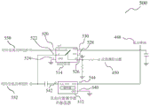
图5显示根据各种实施例的时钟切换电路的示意图。FIG. 5 shows a schematic diagram of a clock switching circuit according to various embodiments.
图6显示根据各种实施例的电源供应电路的概念图。FIG. 6 shows a conceptual diagram of a power supply circuit according to various embodiments.
图7显示根据各种实施例的电源供应电路的概念图。FIG. 7 shows a conceptual diagram of a power supply circuit according to various embodiments.
图8显示根据各种实施例的穿戴式装置的概念图。Figure 8 shows a conceptual diagram of a wearable device according to various embodiments.
图9显示说明根据各种实施例的用于提供电源供应给穿戴式装置的方法的流程图。FIG. 9 shows a flowchart illustrating a method for providing power supply to a wearable device according to various embodiments.
具体实施方式Detailed ways
下文在电源供应电路的情形下所述的实施例针对各别方法类似地有效,且反之亦然。此外,将理解,下文所述的实施例可组合,例如,一实施例的部分可与另一实施例的部分组合。Embodiments described below in the context of a power supply circuit are similarly valid for the respective methods, and vice versa. Furthermore, it will be appreciated that the embodiments described below may be combined, eg parts of one embodiment may be combined with parts of another embodiment.
将理解,本文针对具体装置所述的任何性质亦可在本文所述的任何装置中维持一致。将理解,本文针对具体方法所述的任何性质亦可在本文所述的任何方法中保持一致。此外,将理解,针对本文所述的任何装置或方法,未必所描述的所有组件或步骤必须包括于装置或方法中,而是仅一些(而非所有)组件或步骤可被包括。It will be understood that any property described herein for a particular device may also be maintained consistently across any device described herein. It will be understood that any property described herein for a particular method may also be maintained in any method described herein. Furthermore, it will be understood that with respect to any apparatus or method described herein, not necessarily all components or steps described must be included in the apparatus or method, but only some, but not all, may be included.
在实施例中,“电路”可理解为任何种类的逻辑实施实体,其可为专用电路或储存于内存中的处理器执行软件、固件,或其任何组合。因此,在实施例中,“电路”可为固线式(hard-wired)逻辑电路或诸如可编程处理器的可编程逻辑电路,例如微处理器(例如,复杂指令集计算机(CISC)处理器或精简指令集计算机(RISC)处理器)。“电路”亦可为处理器执行软件,例如任何种类的计算机程序,例如使用诸如Java的虚拟机代码的计算机程序。下文将更详细描述的各功能的任何其他种类的实行方案亦可理解为根据替代性实施例的“电路”。In the embodiments, a "circuit" may be understood as any kind of logic implementation entity, which may be a dedicated circuit or a processor stored in memory executing software, firmware, or any combination thereof. Thus, in embodiments, a "circuit" may be hard-wired logic or programmable logic such as a programmable processor, such as a microprocessor (e.g., a Complex Instruction Set Computer (CISC) processor) or Reduced Instruction Set Computer (RISC) processors). A "circuit" may also be a processor executing software, eg any kind of computer program, eg using virtual machine code such as Java. Any other kind of implementation of the functions which will be described in more detail below may also be understood as a "circuit" according to an alternative embodiment.
本文的术语“耦接”(或“连接”)可理解为电耦接或机械耦接,例如附接或固定,或仅接触而无任何固定,且将理解,直接耦接或间接耦接(换言之:耦接而无直接接触)可得以提供。The term "coupled" (or "connected") herein may be understood as electrically coupled or mechanically coupled, such as attached or fixed, or merely touching without any fixing, and it will be understood that direct coupling or indirect coupling ( In other words: coupling without direct contact) can be provided.
对本说明书中的任何先前技术的参考并未且不应视为承认或任何形式的建议所参考的先前技术形成澳大利亚(或任何其他国家)的已知技术的一部分。Reference to any prior art in this specification is not and should not be taken as an acknowledgment or any form of suggestion that the referenced prior art forms part of the known art in Australia (or any other country).
为了使本发明可容易地理解且付诸实际效果,现将通过实例而非限制且参考附图来描述各种实施例。In order that the present invention may be readily understood and put into practical effect, various embodiments will now be described, by way of example and not limitation, with reference to the accompanying drawings.
穿戴式技术已日益整合至日常生活中。当今,穿戴式装置执行许多不同功能,范围自报时、提供电信、播放视听信号、监视健康统计至追踪活动。经常地,单一穿戴式装置能够执行多个功能,使得用户无需随身携带许多穿戴式装置。结果,与诸如简单数字腕表的单功能装置相比,穿戴式装置的功率消耗速率可为相当高的。同时,以下情形针对穿戴式装置为一般合乎需要的:具有延长的电池寿命,使得其无需为了充电自使用者频繁地脱下。因此,需要可在延长的持续时间内提供不间断电源供应的电源供应电路。Wearable technology is increasingly integrated into everyday life. Today, wearable devices perform many different functions ranging from telling the time, providing telecommunications, playing audiovisual signals, monitoring health statistics to tracking activity. Often, a single wearable device is capable of performing multiple functions, eliminating the need for a user to carry many wearable devices with them. As a result, the power consumption rate of a wearable device can be quite high compared to a single function device such as a simple digital wristwatch. At the same time, it is generally desirable for a wearable device to have extended battery life so that it does not need to be frequently taken off from the user for recharging. Accordingly, there is a need for a power supply circuit that can provide an uninterrupted power supply for an extended duration.
穿戴式装置可包括主电池及次级电池。主电池可用以将电力供应至具有低功率要求的电组件,该等组件在本文中亦称为低功率组件。低功率组件可包括例如定时器或时钟。低功率组件的电流消耗可小于100uA(微安)。次级电池可用以将电力供应至具有高功率要求的电组件,该等组件在本文中亦称为高功率组件。高功率组件的电流消耗可高于100uA,例如高达200mA,例如在自约100uA至约200uA的范围内。高功率组件可包括例如显示屏幕、传感器、处理器、扬声器、振动马达、内存及无线电收发器。无线电收发器可包括例如全球定位系统收发器、蓝牙收发器、Wi-Fi收发器及移动通信收发器。传感器可包括例如陀螺仪、加速度计及温度计。通过双重电池的使用,存在可能缩短穿戴式装置的电池寿命的电流泄漏风险。为了在较长持续时间内提供不间断的电源供应而无需频繁地对电池再充电,根据各种实施例可提供电源供应电路。电源供应电路可对于具有多个微控制器单元(MCU)的穿戴式设备尤其有益。此等穿戴式设备或穿戴式装置可通过主电池源针对诸如记时的超低功率功能需要恒定的不间断供电,且针对诸如蓝牙无线电、振动马达及显示器等的较高功率功能需要次级可再充电电池。A wearable device can include a primary battery and a secondary battery. The main battery can be used to supply power to electrical components with low power requirements, also referred to herein as low power components. Low power components may include, for example, timers or clocks. Current consumption of low-power components can be less than 100uA (microampere). The secondary battery can be used to supply electrical power to electrical components with high power requirements, also referred to herein as high power components. The current consumption of high power components may be higher than 100uA, for example up to 200mA, for example in the range from about 100uA to about 200uA. High power components may include, for example, display screens, sensors, processors, speakers, vibration motors, memory, and radio transceivers. Radio transceivers may include, for example, GPS transceivers, Bluetooth transceivers, Wi-Fi transceivers, and mobile communication transceivers. Sensors may include, for example, gyroscopes, accelerometers, and thermometers. With the use of dual batteries, there is a risk of current leakage that may shorten the battery life of the wearable device. In order to provide an uninterrupted power supply for a longer duration without requiring frequent recharging of the battery, a power supply circuit may be provided according to various embodiments. Power supply circuits can be especially beneficial for wearable devices with multiple microcontroller units (MCUs). These wearable devices or wearable devices can require constant uninterrupted power from a primary battery source for ultra-low power functions such as timekeeping, and a secondary battery for higher power functions such as Bluetooth radios, vibration motors, and displays. Recharge the battery.
在各种实施例的情形下,短语“定时信号”可但不限于可互换地称为“时钟信号”。In the context of various embodiments, the phrase "timing signal" may, without limitation, be referred to interchangeably as a "clock signal."
根据各种实施例,穿戴式装置可包括主电路。主电路可包括低功率组件及高功率组件。穿戴式装置可包括电源切换电路,该电源切换电路配置为在主电池与次级电池之间切换低功率组件的电源供应,使得低功率组件在任何一次仅从一个电源汲取电力。主电池可为诸如钮扣型电池的非可再充电电池。次级电池可为可再充电电池源。高功率组件可仅自次级电池汲取电力。当次级电池不可利用时,高功率组件可切断。当次级电池可利用时,低功率组件可自次级电池而非主电池汲取电力,由此延长主电池的电池寿命。According to various embodiments, a wearable device may include a main circuit. The main circuit may include low power components and high power components. The wearable device may include power switching circuitry configured to switch the power supply of the low power components between the primary battery and the secondary battery such that the low power components draw power from only one power source at any one time. The primary battery may be a non-rechargeable battery such as a button cell. The secondary battery may be a rechargeable battery source. High power components may only draw power from the secondary battery. High power components can be switched off when the secondary battery is not available. When the secondary battery is available, the low power components can draw power from the secondary battery instead of the main battery, thereby extending the battery life of the main battery.
根据各种实施例,穿戴式装置可包括时钟及时钟切换电路。时钟可配置为生成定时信号。定时信号可用以使穿戴式装置中的主动电子组件同步。主动电子组件可包括例如微控制器单元及集成电路。当次级电池不可利用时,时钟切换电路可配置为将定时信号与依赖于次级电池的高功率组件断开连接。此情形可移除时钟上的不必要负载,且亦在次级电池不可利用时最小化高功率组件与低功率组件之间的交叉漏电流。时钟可包括内部电压调节器,以便在遍及主电池与次级电池之间的切换时维持定时信号,甚至当在主电池与次级电池之间存在电压差时亦如此。时钟的内部功率轨可调节至低于电源中的任一个的恒定电压,以确保内部振荡电路将不会归因于波动电压而失去定时准确性。通过最小化电流泄漏,主要电路的总体效率可得以改良。According to various embodiments, a wearable device may include a clock and clock switching circuitry. Clocks can be configured to generate timing signals. Timing signals can be used to synchronize active electronic components in the wearable device. Active electronic components may include, for example, microcontroller units and integrated circuits. When the secondary battery is not available, the clock switching circuit may be configured to disconnect the timing signal from high power components that are dependent on the secondary battery. This can remove unnecessary load on the clock and also minimize cross-leakage current between high and low power components when the secondary battery is not available. The clock may include an internal voltage regulator to maintain the timing signal throughout switching between the primary and secondary batteries, even when there is a voltage differential between the primary and secondary batteries. The clock's internal power rail can be regulated to a constant voltage lower than either of the supplies to ensure that the internal oscillator circuit will not lose timing accuracy due to fluctuating voltages. By minimizing current leakage, the overall efficiency of the main circuits can be improved.
图1显示根据各种实施例的电源供应电路的方框图100。电源供应电路可包括主电池102及次级电池104。次级电池104可为可再充电电池,且与主电池102相比可具有较高的电容或电荷储存容量。与主电池102相比,次级电池104可配置为供应较大量的电功率。电源供应电路可进一步包括可耦接至主电池102及次级电池104中的每一个的电源切换电路106。电源供应电路可进一步包括低功率电路108及高功率电路110。低功率电路108可包括低功率线路。低功率电路108可为必需的总线,使得低功率电路108始终被供电。低功率电路108可将功率供应至与通过高功率电路110供应功率的电组件相比具有较低功率要求的电组件。高功率电路110可包括高功率线路。高功率电路110可为非必需总线,使得高功率电路110可在电池电量即将用尽时断开连接。电源切换电路106可配置为将低功率电路108连接至主电池102或次级电池104中的一个。电源供应电路可进一步包括时钟112。时钟112可为振荡器,例如超低功率振荡器。时钟112可包括微机电系统(MEMS)电路。时钟112可配置为提供时钟信号。时钟112可经由电源切换电路自主电池102或次级电池104接收功率。时钟112可为低功率电路108的部分。信号可提供时钟信号至低功率电路108及高功率电路110以用于同步。为了维持恒定的振荡频率,时钟112可包括配置为提供恒定调节电压作为所接收电压的电压调节器。恒定调节电压可低于主电池102的电压及次级电池104的电压。线130可指示电力线或电耦接。箭头140可指示时钟信号。FIG. 1 shows a block diagram 100 of a power supply circuit according to various embodiments. The power supply circuit can include a
图2显示在次级电池104不可利用或换言之耗尽时的图1的电源供应电路的方框图200。次级电池104的电荷状态可用作次级电池104是否可利用的量度。耗尽阈值可定义为如下电量:在该值以下,次级电池104不能够提供功率。耗尽阈值可为百分比。次级电池104的电荷状态可与耗尽阈值比较,以判定次级电池104是否可利用。举例而言,若电荷状态不超过耗尽阈值,则次级电池104可为耗尽的。当次级电池104耗尽时,电源切换电路106可将次级电池104停用为“关断”状态且将主电池102启动为“接通”状态。电源切换电路106可将电功率自主电池102投送至低功率电路108。时钟112亦可自主电池102接收电功率。电源切换电路106可进行以下操作中的至少一个:自次级电池104解耦或自高功率电路110解耦次级电池104,同时继续将主电池102连接至低功率电路108。时钟切换电路114可使通过时钟112所生成的时钟信号不能发送至高功率电路110,高功率电路110由于其电源被停用现处于“关断”状态。通过使时钟信号不能传输至高功率电路110,时钟112上的负载可减小。高功率电路110与低功率电路108之间的交叉漏电流亦可最小化。FIG. 2 shows a block diagram 200 of the power supply circuit of FIG. 1 when the
图3显示在次级电池104可利用时的图1的电源供应电路的方框图300。次级电池104在其电荷状态超过耗尽阈值时可为可利用的。电池的耗尽阈值可指示电荷电量,在该电荷电量以下,电池耗尽或不能够供应功率。当次级电池104可利用时,电源切换电路106可将电功率自次级电池104投送至低功率电路108及高功率电路110中的每一个。时钟112亦可自次级电池104接收电功率。可停用主电池102,换言之,断开主电池102与低功率电路108及高功率电路110的连接而将主电池102隔离,以节省主电池102中的电池电力。时钟切换电路114可使时钟信号能够提供至高功率电路110。电源切换电路106可通过以下操作最大化主电池102的操作寿命:在次级电池104针对通过高功率电路110所要求的正常较高功率操作可利用时将低功率电路108的功率使用切换至次级电池104。电源切换电路106可在次级电池源切断或耗尽时切换回至主电池源以对低功率组件供电用于低功率操作(例如,记时)。除了自动选择电池源以外,在任何时间使用仅一电池源可最小化由同时使用两个电池源引起的稳态泄漏。此情形可导致针对最大电池寿命的较高总功率效率。FIG. 3 shows a block diagram 300 of the power supply circuit of FIG. 1 when the
图4显示的示意图400示出根据各种实施例的电源供应电路。本文所示的电源切换电路可为电源切换电路106。电源切换电路可包括电源开关406。电源开关406可包括第一电源开关连接器410、第二电源开关连接器412、第三电源开关连接器414、第四电源开关连接器416、第五电源开关连接器418及第六电源开关连接器420。第一电源开关连接器410可耦接至次级源指示器450(指示为“S”)。次级源指示器450可基于次级电池104的状态提供控制信号。次级源指示器450可通过比较次级电池104的电荷状态与预定耗尽阈值而提供控制信号。控制信号在本文中亦可称为指示器信号。电源开关406可配置为基于控制信号操作。电源开关406可通过电源(指示为“VCC”)供电。电源开关406可经由第二电源开关连接器412连接至VCC。电源可为主电池102。第三电源开关连接器414可为耦接至低功率轨448的指示为“Z”的端子。低功率轨448可耦接至至少一低功率组件。第四电源开关连接器416可为耦接至主电池102或主电池功率轨442的指示为“Y0”的端子。第五电源开关连接器418可为耦接至电接地的指示为“GND”的端子。第六电源开关连接器420可为耦接至次级电池104或次级电池源444的指示为“Y1”的端子。当来自次级源指示器450的控制信号指示次级电池104可利用时,电源开关406将第三电源开关连接器414连接至第六电源开关连接器420,使得低功率轨通过次级电池104供电。当控制信号指示次级电池104耗尽时,电源开关406自Y1轻弹至Y0,从而使第三电源开关连接器414连接至第四电源开关连接器416以及自第六电源开关连接器420断开连接。换言之,低功率轨448现通过主电池102供电且现自次级电池104断开连接。次级电池104可连接至高功率轨,而不管次级电池104的电荷状态。当次级电池104耗尽时,次级电池104亦可自高功率轨断开连接。高功率轨可耦接至至少一高功率组件。FIG. 4 shows a schematic diagram 400 illustrating a power supply circuit according to various embodiments. The power switching circuit shown herein may be the
图5显示根据各种实施例的时钟切换电路的示意图500。时钟切换电路可为时钟切换电路114。时钟切换电路可包括时钟512及时钟开关514。时钟512可为振荡器且可为MEMS振荡器。时钟512可包括内置电压调节器。时钟512可具有连接至接地的第一时钟连接器540。时钟512可具有携载时钟512的输出时钟信号的第二时钟连接器542。输出时钟信号在本文中可指示为“CLK_OUT”。第二时钟连接器542可耦接至低功率组件552。时钟512可具有在本文中亦指示为VDD的第三时钟连接器544,第三时钟连接器544用以将功率提供至时钟512。VDD可通过低功率轨448提供。换言之,时钟512可为低功率组件中的一个。电压调节器可将自低功率轨所接收的功率转换为低于主电池102及次级电池104两者的恒定电压。时钟开关514可包括第一时钟开关连接器520、第二时钟开关连接器522、第三时钟开关连接器524、第四时钟开关连接器526、第五时钟开关连接器528及第六时钟开关连接器530。第一时钟开关连接器520可为耦接至高功率组件550的指示为“Y”的端子。第二时钟开关连接器522可为耦接至第二时钟连接器542的指示为“Z”的端子。第三时钟开关连接器524可耦接至电接地。第四时钟开关连接器526可耦接至次级源指示器450。次级源指示器450可生成可用以控制时钟开关514的控制信号。指示为“N.C.”的第五时钟开关连接器528可为非连接的浮动销。第五时钟开关连接器528可连接至电接地。指示为“VCC”的第六时钟开关连接器530可耦接至低功率轨448。换言之,时钟开关514可自低功率轨448接收电功率。当来自次级源指示器450的控制信号指示次级电池104为可利用时,时钟开关514可将第一时钟开关连接器520连接至第二时钟开关连接器522,亦即连接Y与Z,使得输出时钟信号CLK_OUT提供至高功率组件550。当控制信号指示次级电池104不可利用时,时钟开关514可将第一时钟开关连接器520自第二时钟开关连接器522断开连接,亦即将Y与Z断开连接。当Y自Z断开连接时,高功率组件550自时钟512断开连接,且因此不接收输出时钟信号。FIG. 5 shows a schematic diagram 500 of a clock switching circuit according to various embodiments. The clock switching circuit may be the
图6显示根据各种实施例的电源供应电路600的概念图。电源供应电路600可包括电源开关606及时钟开关614。电源开关606可配置为基于次级电源的电荷状态启动主电源或次级电源中的一个。主电源可配置为在启动时对低功率组件供电。次级电源可配置为在启动时对低功率组件及高功率组件供电。时钟开关614可配置为基于次级电源的电荷状态将时钟信号提供至高功率组件。如通过线660所指出,电源开关606及时钟开关614可彼此例如以电耦接、例如使用线或缆线及/或机械性耦接的方式耦接。FIG. 6 shows a conceptual diagram of a
换言之,根据各种实施例,电源供应电路600可包括电源开关606。电源开关606可类似或等同于电源切换电路106。电源开关606可包括电源开关406。电源开关606可配置为基于次级电源的电荷状态启动主电源或次级电源中的一个。主电源可在通过电源开关606启动时对低功率组件供电。次级电源可在通过电源开关606启动时对低功率组件及高功率组件两者供电。换言之,在任一时间,主电源或次级电源为有效的。主电源及次级电源可能不同时运作。主电源为有效的或次级电源为有效的取决于电荷状态,换言之,保留在次级电源中的电荷量。电源开关606可在次级电源的电荷状态超过预定阈值时启动次级电源,且可在次级电源的电荷状态不超过预定阈值时启动主电源。预定阈值可为次级电池104中的电荷的百分比,在其以下,次级电池104耗尽或不能够供应功率。电源的预设选择可为次级电源,使得主电源仅在次级电源耗尽时启动。当次级电源为有效时,低功率组件及高功率组件两者可被供应有电功率。当主电源为有效的时,仅低功率组件可被供应有电功率。电源供应电路600可进一步包括时钟开关614。时钟开关614可等同于或类似于时钟切换电路114。时钟开关614可包括时钟开关514。时钟开关614可基于保留于次级电源中的电荷量(亦即,次级电源的电荷状态)将时钟信号提供至高功率组件。当次级电源的电荷状态超过预定阈值时,时钟信号可提供至高功率组件。时钟信号可为图5中所指示的输出时钟信号CLK_OUT。时钟开关614可一直将时钟信号提供至低功率组件,而不管次级电源的电荷状态。时钟开关614可在次级电源耗尽时对于高功率组件拒绝时钟信号,这是因为高功率组件在次级电源耗尽时可能无法被供电。In other words, according to various embodiments, the
图7显示根据各种实施例的电源供应电路700的概念图。电源供应电路700可类似于电源供应电路600,其可包括电源开关606及时钟开关614。电源供应电路700可进一步包括主电源702及次级电源704。主电源702可包括主电池102。次级电源704可包括次级电池104。次级电源704可为可再充电电池。主电源702的电压可低于次级电源704的电压。电源供应电路700可进一步包括功率监视器750。功率监视器750可配置为生成指示次级电源704的电荷状态是否超过预定阈值的指示器信号,且可进一步配置为将指示器信号提供至电源开关606或时钟开关614中的至少一个。指示器信号可为通过次级源指示器450所生成的控制信号。预定阈值可代表电荷电量,在该电荷电量以下,次级电源耗尽或不能够供应功率。预定阈值可为耗尽阈值。电源开关606可配置为基于指示器信号启动主电源702或次级电源704中的一个。电源开关606可通过将主电源702连接至低功率组件而启动主电源702。电源开关606可通过将次级电源704连接至低功率组件及高功率组件中的至少一个而启动次级电源704。时钟开关614亦可配置为基于指示器信号将时钟信号提供至高功率组件。电源供应电路700可进一步包括配置为生成时钟信号的时钟信号生成器712。时钟信号生成器712可为时钟112或时钟512。时钟信号生成器712可为超低功率振荡器。超低功率振荡器的电流消耗可小于100uA,例如在约100nA至约100uA的范围内,例如在约100nA至约10uA的范围内,例如在自约100nA至约1uA的范围内。时钟信号生成器712可包括MEMS振荡器。时钟开关614可通过将时钟信号生成器712连接至高功率组件而使时钟信号提供至高功率组件。如通过线760所指出,电源开关606、时钟开关614、功率监视器750、时钟信号生成器712、主电源702及次级电源704可例如以电耦接、例如使用线或缆线及/或机械耦接的方式彼此耦接。FIG. 7 shows a conceptual diagram of a
图8显示根据各种实施例的穿戴式装置800的概念图。穿戴式装置800可为智能腕表、健身腕带、活动追踪器、健康监视器、医疗植入物、头戴式耳机、媒体播放器或行动通讯装置中的一个。穿戴式装置800可包括低功率组件882及高功率组件884。低功率组件882可包括记时模块。低功率组件882被连续地供电是期望的。低功率组件882可始终接通。高功率组件884可包括MCU或集成电路中的至少一个。高功率组件884亦可包括显示屏幕,例如发光二极管显示器。高功率组件884可按需运作,例如在用户键入输入信号或启动穿戴式装置以执行某些功能时。穿戴式装置800亦可包括电源供应电路880。低功率电路108可为低功率组件882,或可包括低功率组件882。高功率电路110可为高功率组件884,或可包括高功率组件884。电源供应电路880可包括电源供应电路600或电源供应电路700。穿戴式装置800可包括双重电池电路。FIG. 8 shows a conceptual diagram of a
图9显示说明根据各种实施例的用于提供电源供应给穿戴式装置(诸如穿戴式装置800)的方法的流程图900。该方法可包括步骤990,其中使用电源切换电路基于次级电源的电荷状态启动主电源或次级电源中的一个。当启动时,主电源可对低功率组件供电。当启动时,次级电源可对低功率组件以及高功率组件供电。该方法可进一步包括步骤992,其中可使用时钟开关基于次级电源的电荷状态将时钟信号提供至高功率组件。FIG. 9 shows a
以下实例为进一步的实施例。The following examples are further embodiments.
实例1为一种电源供应电路,其包括:电源开关,其配置为基于次级电源的电荷状态启动主电源或该次级电源中的一个;其中该主电源配置为在启动时对低功率组件供电;且其中该次级电源配置为在启动时对该低功率组件及高功率组件供电;及时钟开关,其配置为基于该次级电源的该电荷状态将时钟信号提供至该高功率组件。Example 1 is a power supply circuit comprising: a power switch configured to activate a primary power supply or one of the secondary power supplies based on a state of charge of the secondary power supply; wherein the primary power supply is configured to activate low power components upon activation and wherein the secondary power supply is configured to power the low power component and the high power component at start-up; and a clock switch is configured to provide a clock signal to the high power component based on the state of charge of the secondary power supply.
在实例2中,实例1的主题可任选地包括功率监视器,该功率监视器配置为生成指示该次级电源的该电荷状态是否超过预定阈值的指示器信号,且进一步配置为将该指示器信号提供至该电源开关或该时钟开关中的至少一个。In Example 2, the subject matter of Example 1 can optionally include a power monitor configured to generate an indicator signal indicating whether the state of charge of the secondary power supply exceeds a predetermined threshold, and further configured to indicate the An output signal is provided to at least one of the power switch or the clock switch.
在实例3中,实例2的主题可任选地包括,该电源开关配置为基于该指示器信号启动该主电源或该次级电源中的一个。In Example 3, the subject matter of Example 2 can optionally include the power switch configured to activate one of the primary power supply or the secondary power supply based on the indicator signal.
在实例4中,实例2或实例3的主题可任选地包括,该时钟开关配置为基于该指示器信号将该时钟信号提供至该高功率组件。In Example 4, the subject matter of Example 2 or Example 3 can optionally include the clock switch configured to provide the clock signal to the high power component based on the indicator signal.
在实例5中,实例1至4中任一个的主题可任选地包括时钟信号生成器,该时钟信号生成器配置为生成该时钟信号。In Example 5, the subject matter of any one of Examples 1 to 4 can optionally include a clock signal generator configured to generate the clock signal.
在实例6中,实例5的主题可任选地包括,该时钟开关配置为通过将该时钟信号生成器连接至该高功率组件而将该时钟信号提供至该高功率组件。In Example 6, the subject matter of Example 5 can optionally include the clock switch configured to provide the clock signal to the high power component by connecting the clock signal generator to the high power component.
在实例7中,实例5或实例6的主题可任选地包括,该时钟信号生成器配置为无论该次级电源的该电荷状态如何都将该时钟信号提供至该低功率组件。In Example 7, the subject matter of Example 5 or Example 6 can optionally include the clock signal generator being configured to provide the clock signal to the low power component regardless of the state of charge of the secondary power supply.
在实例8中,实例5至7中任一个的主题可任选地包括,该时钟信号生成器包括振荡器。In Example 8, the subject matter of any one of Examples 5 to 7 can optionally include that the clock signal generator comprises an oscillator.
在实例9中,实例8的主题可任选地包括,该时钟信号生成器进一步包括电压调节器。In Example 9, the subject matter of Example 8 can optionally include, the clock signal generator further comprising a voltage regulator.
在实例10中,实例9的主题可任选地包括,该电压调节器配置为将恒定调节电压提供至该振荡器。In Example 10, the subject matter of Example 9 can optionally include the voltage regulator configured to provide a constant regulated voltage to the oscillator.
在实例11中,实例10的主题可任选地包括,该恒定调节电压低于该主电源的电压及该次级电源的电压中的每一个。In Example 11, the subject matter of Example 10 can optionally include that the constant regulated voltage is lower than each of the voltage of the primary power supply and the voltage of the secondary power supply.
在实例12中,实例8至11中任一个的主题可任选地包括,该振荡器为超低功率振荡器。In Example 12, the subject matter of any one of Examples 8 to 11 can optionally include that the oscillator is an ultra-low power oscillator.
在实例13中,实例1至12中任一个的主题可任选地包括,该电源开关配置为在该次级电源的该电荷状态超过预定阈值时启动该次级电源,且其中该电源开关配置为在该次级电源的该电荷状态未超过该预定阈值时启动该主电源。In Example 13, the subject matter of any one of Examples 1 to 12 can optionally include that the power switch is configured to activate the secondary power supply when the state of charge of the secondary power supply exceeds a predetermined threshold, and wherein the power switch is configured activating the primary power supply when the state of charge of the secondary power supply does not exceed the predetermined threshold.
在实例14中,实例1至13中任一个的主题可任选地包括,该时钟开关配置为在该次级电源的该电荷状态超过预定阈值时将该时钟信号提供至该高功率组件。In Example 14, the subject matter of any one of Examples 1 to 13 can optionally include the clock switch configured to provide the clock signal to the high power component when the state of charge of the secondary power supply exceeds a predetermined threshold.
在实例15中,实例1至14中任一个的主题可任选地包括,该电源开关配置为通过将该主电源或该次级电源中的一个连接至该低功率组件而启动该主电源或该次级电源中的一个。In Example 15, the subject matter of any one of Examples 1 to 14 can optionally include that the power switch is configured to activate the primary power supply or the secondary power supply by connecting one of the primary power supply or the secondary power supply to the low power component one of the secondary power supplies.
在实例16中,实例1至15中任一个的主题可任选地包括,无论该次级电源的该电荷状态如何,该次级电源连接至该高功率组件。In Example 16, the subject matter of any one of Examples 1 to 15 can optionally include, regardless of the state of charge of the secondary power supply, connecting the secondary power supply to the high power component.
在实例17中,实例1至16中任一个的主题可任选地包括,该主电源及该次级电源中的每一个为电池。In Example 17, the subject matter of any one of Examples 1 to 16 can optionally include that each of the primary power source and the secondary power source is a battery.
在实例18中,实例1至17中任一个的主题可任选地包括,该次级电源为可再充电电池。In Example 18, the subject matter of any one of Examples 1 to 17 can optionally include that the secondary power source is a rechargeable battery.
在实例19中,实例1至18中任一个的主题可任选地包括,该主电源的电压低于该次级电源的电压。In Example 19, the subject matter of any one of Examples 1 to 18 can optionally include that the voltage of the primary power supply is lower than the voltage of the secondary power supply.
在实例20中,实例1至19中任一个的主题可任选地包括该主电源;及该次级电源。In Example 20, the subject matter of any one of Examples 1 to 19 can optionally include the primary power supply; and the secondary power supply.
实例21为一种穿戴式装置,其包括:低功率组件;高功率组件;电源供应电路,其包括:电源开关,其配置为基于次级电源的电荷状态启动主电源或该次级电源中的一个;其中该主电源配置为在启动时对低功率组件供电;且其中该次级电源配置为在启动时对该低功率组件及高功率组件供电;及时钟开关,其配置为基于该次级电源的该电荷状态将时钟信号提供至该高功率组件。Example 21 is a wearable device comprising: a low power component; a high power component; a power supply circuit comprising: a power switch configured to activate a primary power source or a power source in the secondary power source based on a state of charge of the secondary power source a; wherein the primary power supply is configured to power the low power component at startup; and wherein the secondary power supply is configured to power the low power component and the high power component at startup; and a clock switch configured to power the low power component based on the secondary The state of charge of the power supply provides a clock signal to the high power component.
在实例22中,实例21的主题可任选地包括,该低功率组件包括记时模块。In Example 22, the subject matter of Example 21 can optionally include, the low power component comprising a timing module.
在实例23中,实例21或实例22的主题可任选地包括,该高功率组件包括微控制器单元或集成电路中的至少一个。In Example 23, the subject matter of Example 21 or Example 22 can optionally include that the high power component comprises at least one of a microcontroller unit or an integrated circuit.
实例24为一种用于提供电源供应给穿戴式装置的方法,该方法包括:使用电源切换电路基于次级电源的电荷状态启动主电源或该次级电源中的一个;其中该主电源在启动时对低功率组件供电;且其中该次级电源在启动时对该低功率组件及高功率组件供电;及使用时钟开关基于该次级电源的该电荷状态将时钟信号提供至该高功率组件。Example 24 is a method for providing a power supply to a wearable device, the method comprising: using a power switching circuit to activate a primary power supply or one of the secondary power supplies based on a state of charge of the secondary power supply; wherein the primary power supply is powering the low power component at all times; and wherein the secondary power supply powers the low power component and the high power component at startup; and using a clock switch to provide a clock signal to the high power component based on the state of charge of the secondary power supply.
尽管已参考具体实施例特定地显示且描述了本发明的实施例,但本领域技术人员应理解,在不脱离如通过所附申请专利范围所界定的本发明的精神及范畴的情况下,可在实施例中进行形式及细节上的各种改变。本发明的范畴因此通过所附申请专利范围来指示,且属于申请专利范围的等效性的含义及范围内的所有改变因此被包含。将了解,在相关附图中所使用的相同数字指代用于类似或相同目的的组件。While embodiments of the present invention have been particularly shown and described with reference to specific embodiments, it will be appreciated by those skilled in the art that other modifications may be made without departing from the spirit and scope of the invention as defined by the appended claims. Various changes in form and details were made in the embodiments. The scope of the invention is thus indicated by the appended claims and all changes which come within the meaning and range of equivalents of the claims are therefore embraced. It will be appreciated that like numerals are used in related figures to designate components serving similar or identical purposes.
Claims (21)
Applications Claiming Priority (1)
| Application Number | Priority Date | Filing Date | Title |
|---|---|---|---|
| PCT/SG2017/050068 WO2018151665A1 (en) | 2017-02-16 | 2017-02-16 | Power supply circuits, wearable devices and methods for providing power supply to a wearable device |
Publications (2)
| Publication Number | Publication Date |
|---|---|
| CN110300943A CN110300943A (en) | 2019-10-01 |
| CN110300943B true CN110300943B (en) | 2023-04-25 |
Family
ID=63169968
Family Applications (1)
| Application Number | Title | Priority Date | Filing Date |
|---|---|---|---|
| CN201780086508.XA Active CN110300943B (en) | 2017-02-16 | 2017-02-16 | Power supply circuit, wearable device and method for providing power supply for wearable device |
Country Status (7)
| Country | Link |
|---|---|
| US (1) | US10901480B2 (en) |
| EP (1) | EP3583484B1 (en) |
| CN (1) | CN110300943B (en) |
| AU (1) | AU2017399575B2 (en) |
| SG (1) | SG11201907234TA (en) |
| TW (1) | TWI759428B (en) |
| WO (1) | WO2018151665A1 (en) |
Families Citing this family (4)
| Publication number | Priority date | Publication date | Assignee | Title |
|---|---|---|---|---|
| US11275663B2 (en) * | 2020-06-08 | 2022-03-15 | Intel Corporation | Fast dynamic capacitance, frequency, and/or voltage throttling apparatus and method |
| TWI818305B (en) * | 2020-10-29 | 2023-10-11 | 宏達國際電子股份有限公司 | Head mounted display device and power management method thereof |
| US20230280809A1 (en) * | 2022-03-01 | 2023-09-07 | Venkataramani Gopalakrishnan | Method and apparatus to control power supply rails during platform low power events for enhanced usb-c user experience |
| CN119742894A (en) * | 2024-12-31 | 2025-04-01 | 昆山联滔电子有限公司 | Power supply device and power management method |
Citations (1)
| Publication number | Priority date | Publication date | Assignee | Title |
|---|---|---|---|---|
| CN101087104A (en) * | 2006-06-08 | 2007-12-12 | 恩益禧电子股份有限公司 | Power supply circuit |
Family Cites Families (25)
| Publication number | Priority date | Publication date | Assignee | Title |
|---|---|---|---|---|
| JPH07307696A (en) | 1994-05-12 | 1995-11-21 | Oki Electric Ind Co Ltd | Portable electronic device |
| US6256744B1 (en) * | 1998-09-21 | 2001-07-03 | Compaq Computer Corporation | Personal computer component signal line isolation for an auxiliary powered component |
| US6545445B1 (en) | 2000-05-08 | 2003-04-08 | Gp Batteries International, Ltd. | Multiple battery system and method |
| US7339347B2 (en) | 2003-08-11 | 2008-03-04 | Reserve Power Cell, Llc | Apparatus and method for reliably supplying electrical energy to an electrical system |
| CN101171718B (en) | 2005-03-11 | 2012-08-22 | 泰克蒂姆有限公司 | Bidirectional Battery Charge Controller |
| US7761198B2 (en) * | 2007-06-25 | 2010-07-20 | General Electric Company | Methods and systems for power system management |
| US20090083000A1 (en) * | 2007-09-26 | 2009-03-26 | Modu Ltd. | Automated appliance diagnostics and reporting |
| US7863862B2 (en) | 2007-10-12 | 2011-01-04 | Research In Motion Limited | Handheld electronic device with holster having a notification device |
| US8791600B2 (en) | 2007-12-21 | 2014-07-29 | Roger J. Soar | Vehicle seat inductive charger and data transmitter |
| WO2009148595A2 (en) | 2008-06-03 | 2009-12-10 | Jonathan Arnold Bell | Wearable electronic system |
| US20100114235A1 (en) | 2008-10-31 | 2010-05-06 | Pacesetter Inc. | Hybrid battery system for implantable cardiac therapy device |
| US20120091816A1 (en) | 2010-11-15 | 2012-04-19 | O2Micro, Inc. | Power systems with multiple power sources |
| US9018893B2 (en) | 2011-03-18 | 2015-04-28 | Medtronic Minimed, Inc. | Power control techniques for an electronic device |
| US8564447B2 (en) | 2011-03-18 | 2013-10-22 | Medtronic Minimed, Inc. | Battery life indication techniques for an electronic device |
| TWI462430B (en) * | 2012-02-02 | 2014-11-21 | Wistron Corp | Power management system |
| WO2014153034A1 (en) | 2013-03-14 | 2014-09-25 | Milwaukee Electric Tool Corporation | Power tool having multiple battery packs |
| US9242109B2 (en) * | 2013-03-15 | 2016-01-26 | Medtronic, Inc. | Apparatus and methods facilitating power regulation for an implantable device |
| US9214710B1 (en) | 2013-09-26 | 2015-12-15 | The United States Of America As Represented By The Secretary Of The Navy | Hybrid battery power system |
| TW201523225A (en) * | 2013-12-12 | 2015-06-16 | Acer Inc | Power management method and portable computer using the same |
| US9549273B2 (en) * | 2014-08-28 | 2017-01-17 | Qualcomm Incorporated | Selective enabling of a component by a microphone circuit |
| US10248180B2 (en) * | 2014-10-16 | 2019-04-02 | Futurewei Technologies, Inc. | Fast SMP/ASMP mode-switching hardware apparatus for a low-cost low-power high performance multiple processor system |
| TW201616771A (en) * | 2014-10-20 | 2016-05-01 | 和碩聯合科技股份有限公司 | Power adapter and electronic system using the same |
| US10516294B2 (en) * | 2015-02-09 | 2019-12-24 | Eaton Intelligent Power Limited | Uninterruptible constant current regulator |
| CN106708250A (en) * | 2015-08-06 | 2017-05-24 | 微软技术许可有限责任公司 | Wearable device |
| CN105515173A (en) * | 2015-12-07 | 2016-04-20 | 北京奇虎科技有限公司 | Wearable device and method thereof for managing application program according to electric quantity |
-
2017
- 2017-02-16 CN CN201780086508.XA patent/CN110300943B/en active Active
- 2017-02-16 US US16/484,433 patent/US10901480B2/en active Active
- 2017-02-16 EP EP17896626.3A patent/EP3583484B1/en active Active
- 2017-02-16 SG SG11201907234TA patent/SG11201907234TA/en unknown
- 2017-02-16 WO PCT/SG2017/050068 patent/WO2018151665A1/en not_active Ceased
- 2017-02-16 AU AU2017399575A patent/AU2017399575B2/en active Active
-
2018
- 2018-02-14 TW TW107105534A patent/TWI759428B/en active
Patent Citations (1)
| Publication number | Priority date | Publication date | Assignee | Title |
|---|---|---|---|---|
| CN101087104A (en) * | 2006-06-08 | 2007-12-12 | 恩益禧电子股份有限公司 | Power supply circuit |
Also Published As
| Publication number | Publication date |
|---|---|
| AU2017399575A1 (en) | 2019-08-29 |
| SG11201907234TA (en) | 2019-09-27 |
| TWI759428B (en) | 2022-04-01 |
| US20190369701A1 (en) | 2019-12-05 |
| US10901480B2 (en) | 2021-01-26 |
| CN110300943A (en) | 2019-10-01 |
| WO2018151665A1 (en) | 2018-08-23 |
| EP3583484A1 (en) | 2019-12-25 |
| TW201835715A (en) | 2018-10-01 |
| EP3583484B1 (en) | 2023-08-09 |
| AU2017399575B2 (en) | 2022-09-29 |
| EP3583484A4 (en) | 2020-02-26 |
Similar Documents
| Publication | Publication Date | Title |
|---|---|---|
| US10652828B2 (en) | Electronic device for providing mode switching and a method thereof | |
| JP4918866B2 (en) | COMMUNICATION DEVICE, SEMICONDUCTOR INTEGRATED CIRCUIT DEVICE, AND COMMUNICATION SYSTEM | |
| CN110300943B (en) | Power supply circuit, wearable device and method for providing power supply for wearable device | |
| US9841805B2 (en) | Power management circuit and electronic device employing the same | |
| US8140129B2 (en) | Mobile phone terminal and communication system | |
| KR20180101930A (en) | Electronic Apparatus for checking battery abnormality and the Control method thereof | |
| CN103186164B (en) | Clock generator and clock signal generation method | |
| CN109842185B (en) | Portable information processing device, integrated circuit, and battery pack | |
| US11695291B2 (en) | Method to charge battery and electronic device including battery | |
| CN106155252A (en) | Electronic equipment and method for distributing power on electronic equipment | |
| US20120056480A1 (en) | Control device, electronic apparatus, timepiece device, and control method | |
| US9356459B2 (en) | Method for charging battery and electronic device thereof | |
| US20080246549A1 (en) | Real time clock integrated circuit and electronic apparatus using the same | |
| US10514744B2 (en) | Portable computing device with hibernate mode | |
| US8022676B2 (en) | Electronic device | |
| WO2019218821A1 (en) | Dual-battery switching method and circuit, mobile terminal and storage medium | |
| JP2016119735A (en) | Electronic clock and electronic apparatus | |
| US20150125017A1 (en) | Hearing device using multiple batteries and method of managing power of hearing device | |
| JP6984186B2 (en) | Charge control device, charge control method and program | |
| CN104977843A (en) | Watch | |
| US11960343B2 (en) | Remote controller and controlling method thereof | |
| JP2025004278A (en) | Electronic device, electronic clock, reset control circuit and reset method | |
| JP2010258680A (en) | Portable terminal, portable terminal system, and method and program for warning battery remaining capacity | |
| JP2016105064A (en) | Electronic watch, electronic apparatus, program, and communication system | |
| EP4391507A1 (en) | Mobile information terminal and method for controlling same |
Legal Events
| Date | Code | Title | Description |
|---|---|---|---|
| PB01 | Publication | ||
| PB01 | Publication | ||
| SE01 | Entry into force of request for substantive examination | ||
| SE01 | Entry into force of request for substantive examination | ||
| GR01 | Patent grant | ||
| GR01 | Patent grant |