CN110049909B - Vehicle control device - Google Patents
Vehicle control device Download PDFInfo
- Publication number
- CN110049909B CN110049909B CN201780075399.1A CN201780075399A CN110049909B CN 110049909 B CN110049909 B CN 110049909B CN 201780075399 A CN201780075399 A CN 201780075399A CN 110049909 B CN110049909 B CN 110049909B
- Authority
- CN
- China
- Prior art keywords
- vehicle
- region
- speed
- curved
- road
- Prior art date
- Legal status (The legal status is an assumption and is not a legal conclusion. Google has not performed a legal analysis and makes no representation as to the accuracy of the status listed.)
- Active
Links
Images


Classifications
-
- B—PERFORMING OPERATIONS; TRANSPORTING
- B60—VEHICLES IN GENERAL
- B60W—CONJOINT CONTROL OF VEHICLE SUB-UNITS OF DIFFERENT TYPE OR DIFFERENT FUNCTION; CONTROL SYSTEMS SPECIALLY ADAPTED FOR HYBRID VEHICLES; ROAD VEHICLE DRIVE CONTROL SYSTEMS FOR PURPOSES NOT RELATED TO THE CONTROL OF A PARTICULAR SUB-UNIT
- B60W30/00—Purposes of road vehicle drive control systems not related to the control of a particular sub-unit, e.g. of systems using conjoint control of vehicle sub-units
- B60W30/14—Adaptive cruise control
- B60W30/143—Speed control
- B60W30/146—Speed limiting
-
- B—PERFORMING OPERATIONS; TRANSPORTING
- B60—VEHICLES IN GENERAL
- B60W—CONJOINT CONTROL OF VEHICLE SUB-UNITS OF DIFFERENT TYPE OR DIFFERENT FUNCTION; CONTROL SYSTEMS SPECIALLY ADAPTED FOR HYBRID VEHICLES; ROAD VEHICLE DRIVE CONTROL SYSTEMS FOR PURPOSES NOT RELATED TO THE CONTROL OF A PARTICULAR SUB-UNIT
- B60W30/00—Purposes of road vehicle drive control systems not related to the control of a particular sub-unit, e.g. of systems using conjoint control of vehicle sub-units
- B60W30/08—Active safety systems predicting or avoiding probable or impending collision or attempting to minimise its consequences
- B60W30/09—Taking automatic action to avoid collision, e.g. braking and steering
-
- B—PERFORMING OPERATIONS; TRANSPORTING
- B60—VEHICLES IN GENERAL
- B60W—CONJOINT CONTROL OF VEHICLE SUB-UNITS OF DIFFERENT TYPE OR DIFFERENT FUNCTION; CONTROL SYSTEMS SPECIALLY ADAPTED FOR HYBRID VEHICLES; ROAD VEHICLE DRIVE CONTROL SYSTEMS FOR PURPOSES NOT RELATED TO THE CONTROL OF A PARTICULAR SUB-UNIT
- B60W30/00—Purposes of road vehicle drive control systems not related to the control of a particular sub-unit, e.g. of systems using conjoint control of vehicle sub-units
- B60W30/08—Active safety systems predicting or avoiding probable or impending collision or attempting to minimise its consequences
- B60W30/095—Predicting travel path or likelihood of collision
- B60W30/0953—Predicting travel path or likelihood of collision the prediction being responsive to vehicle dynamic parameters
-
- B—PERFORMING OPERATIONS; TRANSPORTING
- B60—VEHICLES IN GENERAL
- B60W—CONJOINT CONTROL OF VEHICLE SUB-UNITS OF DIFFERENT TYPE OR DIFFERENT FUNCTION; CONTROL SYSTEMS SPECIALLY ADAPTED FOR HYBRID VEHICLES; ROAD VEHICLE DRIVE CONTROL SYSTEMS FOR PURPOSES NOT RELATED TO THE CONTROL OF A PARTICULAR SUB-UNIT
- B60W30/00—Purposes of road vehicle drive control systems not related to the control of a particular sub-unit, e.g. of systems using conjoint control of vehicle sub-units
- B60W30/08—Active safety systems predicting or avoiding probable or impending collision or attempting to minimise its consequences
- B60W30/095—Predicting travel path or likelihood of collision
- B60W30/0956—Predicting travel path or likelihood of collision the prediction being responsive to traffic or environmental parameters
-
- B—PERFORMING OPERATIONS; TRANSPORTING
- B60—VEHICLES IN GENERAL
- B60W—CONJOINT CONTROL OF VEHICLE SUB-UNITS OF DIFFERENT TYPE OR DIFFERENT FUNCTION; CONTROL SYSTEMS SPECIALLY ADAPTED FOR HYBRID VEHICLES; ROAD VEHICLE DRIVE CONTROL SYSTEMS FOR PURPOSES NOT RELATED TO THE CONTROL OF A PARTICULAR SUB-UNIT
- B60W30/00—Purposes of road vehicle drive control systems not related to the control of a particular sub-unit, e.g. of systems using conjoint control of vehicle sub-units
- B60W30/10—Path keeping
-
- B—PERFORMING OPERATIONS; TRANSPORTING
- B60—VEHICLES IN GENERAL
- B60W—CONJOINT CONTROL OF VEHICLE SUB-UNITS OF DIFFERENT TYPE OR DIFFERENT FUNCTION; CONTROL SYSTEMS SPECIALLY ADAPTED FOR HYBRID VEHICLES; ROAD VEHICLE DRIVE CONTROL SYSTEMS FOR PURPOSES NOT RELATED TO THE CONTROL OF A PARTICULAR SUB-UNIT
- B60W2552/00—Input parameters relating to infrastructure
- B60W2552/30—Road curve radius
-
- B—PERFORMING OPERATIONS; TRANSPORTING
- B60—VEHICLES IN GENERAL
- B60W—CONJOINT CONTROL OF VEHICLE SUB-UNITS OF DIFFERENT TYPE OR DIFFERENT FUNCTION; CONTROL SYSTEMS SPECIALLY ADAPTED FOR HYBRID VEHICLES; ROAD VEHICLE DRIVE CONTROL SYSTEMS FOR PURPOSES NOT RELATED TO THE CONTROL OF A PARTICULAR SUB-UNIT
- B60W2554/00—Input parameters relating to objects
- B60W2554/80—Spatial relation or speed relative to objects
- B60W2554/801—Lateral distance
-
- B—PERFORMING OPERATIONS; TRANSPORTING
- B60—VEHICLES IN GENERAL
- B60W—CONJOINT CONTROL OF VEHICLE SUB-UNITS OF DIFFERENT TYPE OR DIFFERENT FUNCTION; CONTROL SYSTEMS SPECIALLY ADAPTED FOR HYBRID VEHICLES; ROAD VEHICLE DRIVE CONTROL SYSTEMS FOR PURPOSES NOT RELATED TO THE CONTROL OF A PARTICULAR SUB-UNIT
- B60W2554/00—Input parameters relating to objects
- B60W2554/80—Spatial relation or speed relative to objects
- B60W2554/802—Longitudinal distance
-
- B—PERFORMING OPERATIONS; TRANSPORTING
- B60—VEHICLES IN GENERAL
- B60W—CONJOINT CONTROL OF VEHICLE SUB-UNITS OF DIFFERENT TYPE OR DIFFERENT FUNCTION; CONTROL SYSTEMS SPECIALLY ADAPTED FOR HYBRID VEHICLES; ROAD VEHICLE DRIVE CONTROL SYSTEMS FOR PURPOSES NOT RELATED TO THE CONTROL OF A PARTICULAR SUB-UNIT
- B60W2554/00—Input parameters relating to objects
- B60W2554/80—Spatial relation or speed relative to objects
- B60W2554/804—Relative longitudinal speed
Landscapes
- Engineering & Computer Science (AREA)
- Automation & Control Theory (AREA)
- Transportation (AREA)
- Mechanical Engineering (AREA)
- Traffic Control Systems (AREA)
- Control Of Driving Devices And Active Controlling Of Vehicle (AREA)
Abstract
An ECU (10) mounted on a vehicle (1) detects a preceding vehicle (3) located in front of the vehicle (1), setting a speed distribution region (40, 50) in at least a part of the periphery of a preceding vehicle (3), the speed distribution regions (40, 50) define the distribution of the allowable upper limit value Vlim of the relative speed of the vehicle (1) to the preceding vehicle (3) in the traveling direction of the vehicle (1) and execute the traveling control, in order to suppress the relative speed of a vehicle (1) with respect to a preceding vehicle (3) from exceeding an allowable upper limit value Vlim within a speed distribution region (40, 50), in the speed distribution region (50), when the road (5) on which the preceding vehicle (3) is located is curved, in the side region of the speed distribution region, the equal relative speed lines d, e, f connecting points having the same allowable upper limit value Vlim are curved in accordance with the curvature of the curved road (5).
Description
Technical Field
The present invention relates to a vehicle control device, and more particularly to a vehicle control device that assists safe travel of a vehicle.
Background
Conventionally, a vehicle is equipped with a plurality of safe driving support systems including a lane keeping assist system and an auto cruise system. In these systems, automatic braking control, steering assist control, and the like are used, respectively. Therefore, a brake request signal for performing automatic brake control and a steering request signal for performing steering assist control may be transmitted from each system. For example, the brake request signals are sometimes sent from different systems at different timings, respectively. In this case, priority is given to 1 request signal out of the plurality of request signals (see, for example, patent document 1).
Documents of the prior art
Patent document
Patent documents: japanese patent laid-open publication No. 2011-51547
Disclosure of Invention
Problems to be solved by the invention
However, the safe driving support system becomes further complicated in the future, and the safe driving support system as a whole may not function efficiently by giving priority to only 1 request signal.
The present invention has been made to solve the above-described problems, and an object thereof is to provide a vehicle control device capable of efficiently executing vehicle control for safe driving support.
Means for solving the problems
In order to achieve the above object, the present invention is a vehicle control device mounted on a vehicle, wherein an object in front of the vehicle is detected, a velocity distribution region is set in at least a part of a periphery of the object, the velocity distribution region defining a distribution of an allowable upper limit value of a relative velocity of the vehicle with respect to the object in a traveling direction of the vehicle, travel control is performed in the velocity distribution region so as to suppress the relative velocity of the vehicle with respect to the object from exceeding the allowable upper limit value, and the velocity distribution region is set so as to have a curve region in which a constant relative velocity line connecting points having the same allowable upper limit value curves in accordance with a curvature of a road in at least one of side regions of the velocity distribution region when the road on which the object is located curves.
According to the present invention configured as described above, the velocity distribution region is set in at least a part of the periphery of the object. In this speed distribution region, an allowable upper limit value of the relative speed of the vehicle with respect to the object is set. The vehicle control device controls the relative speed of the vehicle with respect to the object so as not to exceed the allowable upper limit value set in the speed profile region. As described above, according to the present invention, since the allowable upper limit value of the relative speed between the object and the vehicle is limited and the safe driving support system such as the automatic brake control and the steering assist control is comprehensively controlled, the safe driving support can be provided by the simple and effective speed control.
In the present invention, when the road on which the object is located is curved, the speed distribution region is set to have a curved region in at least one of the side regions of the speed distribution region, and the relative speed lines connecting points having the same allowable upper limit value in the curved region are curved in accordance with the curvature of the road. Here, in the case where the road curves, if the speed distribution region is set as in the case of a straight road, a part of the speed distribution region may exceed the lane boundary line of the road. In this case, even if the vehicle runs in an adjacent lane, for example, the running speed of the vehicle is limited by an allowable upper limit value set so as to exceed the running lane of the vehicle, or the course of travel is changed, which is undesirable deceleration or steering avoidance for the passenger. Here, in the present invention, when the road on which the object is located is curved, the speed distribution region has a curved region in at least one of the side regions of the speed distribution region, and in this curved region, relative speed lines such as lines connecting points having the same allowable upper limit value are curved in accordance with the curvature of the road, so that the speed distribution region is set in accordance with the shape of the road, and unnecessary deceleration or steering of the vehicle can be avoided. This makes it possible to provide driving support that gives the passengers a sense of security and safety.
In the present invention, it is preferable that the speed distribution region has a curved region only in a side region on a side close to the vehicle when the vehicle is at a position laterally offset from the object in the front-rear direction.
According to the present invention thus constituted, when the vehicle is offset in the lateral direction with respect to the front-rear direction of the object, the curved region is provided only in the side region on the side closer to the vehicle. Here, when the vehicle is offset in the lateral direction with respect to the front-rear direction of the object, the possibility that the vehicle approaches the object in the side region of the object closer to the vehicle is higher than the possibility that the vehicle approaches the object in the side region of the object farther from the vehicle. Here, in the present invention, the speed distribution region is set to have the curved region only in the side region on the side closer to the vehicle among the side regions of the speed distribution region, and the speed distribution region corresponding to the shape of the road is set only in a necessary region, so that it is possible to realize the driving support of safety and security by simple calculation processing.
In the present invention, it is preferable that the speed distribution region has an allowable upper limit value zero region where the allowable upper limit value becomes zero at a position separated from the object by a predetermined distance, and has an entry prohibition region where entry of the vehicle is prohibited at a position closer to the object than the relative speed zero region.
According to the present invention thus constituted, the speed distribution region has the permission upper limit value zero region in which the permission upper limit value is zero and the vehicle entrance prohibition region in which the vehicle entrance is prohibited. Therefore, for example, when the vehicle approaches the object and enters the allowable upper limit value zero region, the allowable upper limit value of the relative speed is controlled to be zero, and therefore the vehicle does not approach the object any further. Thus, the vehicle control device can perform safe vehicle driving support.
In addition, if the vehicle approaches the object further within the allowable upper limit value zero range due to an unexpected behavior of the object, the entry prohibition range is set for the object, and therefore the vehicle is subjected to the braking/steering control and does not enter the entry prohibition range. Therefore, even when braking/steering control is performed to avoid a collision, a predetermined distance is secured between the vehicle and the object, and thus, it is possible to perform driving assistance that is safe and safe without making the passenger feel uncomfortable.
In the present invention, it is preferable that the speed distribution area has an entrance prohibition area for prohibiting entry of a vehicle at a position separated by a predetermined distance from the object, and when the road on which the object is located is curved, at least one of the side areas of the speed distribution area has a constant relative speed line set along the entrance prohibition area at the side of the entrance prohibition area, and the curved area is set before and after the entrance prohibition area.
According to the present invention thus constituted, in the case where the road on which the object is located is curved, the speed distribution region is set along the entrance prohibition region at the side of the entrance prohibition region, at least one of the side regions of the speed distribution region, and the constant relative speed line, and the curved region is set before and after the entrance prohibition region. Here, in the case where the road curves, if the speed distribution region is set as in the case of a straight road, a part of the speed distribution region may exceed the lane boundary line of the road. In this case, for example, even if the vehicle is traveling in an adjacent lane, the traveling speed of the vehicle may be limited or the course may be changed because the allowable upper limit value set for the traveling lane of the vehicle is exceeded, which is undesirable deceleration or steering for the passenger. Here, in the present invention, when the road on which the object is located is curved, the speed distribution region is set in at least one of the side regions of the speed distribution region, the equal relative speed line is set along the entrance prohibition region in the side of the entrance prohibition region, and the curved region is set in the front and rear of the entrance prohibition region, so that the speed distribution region corresponding to the shape of the road is set, and unnecessary deceleration or steering of the vehicle is avoided. This makes it possible to provide driving support that gives the passengers a sense of security and safety.
In the present invention, it is preferable that the entrance prohibition area is set to be substantially rectangular, and when the road on which the object is located is curved, at least one of the side areas of the speed distribution area has a constant relative speed line set to be linear in parallel with the side boundary line of the entrance prohibition area on the side of the entrance prohibition area, and the curved area is set before and after the entrance prohibition area.
According to the present invention configured as described above, the entry prohibited area is set to be substantially rectangular, and the entry prohibited area can be set by simple calculation processing. Further, since the curve region of the speed distribution region is set before and after entering the prohibition region, the speed distribution region is suppressed from going beyond the road. On the other hand, since the entrance prohibition area is linearly set in parallel with the side boundary line of the entrance prohibition area on the side, the side boundary line of the entrance prohibition area and the constant relative velocity line do not come too close to each other, and a predetermined distance is secured therebetween. Here, for example, when the vehicle approaches the object from the side, if the constant relative velocity line is set at a small interval with respect to the entrance prohibition area, the vehicle must be decelerated suddenly. In the present invention, the constant relative velocity line is set to be linear in parallel to the side boundary line of the no-entry region on the side of the no-entry region, so that the above-described brake control can be avoided. Therefore, the passenger can feel more reassurance and safety, and more comfortable driving support can be provided.
In the present invention, it is preferable that the entrance prohibition area is set to be enlarged as the moving speed of the object is increased.
According to the present invention thus configured, the entrance prohibition area is set to be enlarged as the moving speed of the object is increased. Here, the driver of the vehicle takes a larger distance from the object or travels at a smaller relative speed to the object as the moving speed of the object is larger. In the present invention, the entrance prohibition area is set to be enlarged as the moving speed of the object is increased, and it is possible to provide driving support that gives the passengers a sense of security and safety.
In the present invention, it is preferable that, when the vehicle is at a position laterally offset with respect to the front-rear direction of the object, the speed distribution region is set such that the constant relative speed line is set along the entry prohibition region on the side of the entry prohibition region and the curved region is set on the front-rear side of the entry prohibition region only in the side region on the side close to the vehicle.
According to the present invention thus constituted, when the vehicle is displaced in the lateral direction with respect to the front-rear direction of the object, the constant relative velocity line is set along the entrance prohibition region on the side of the entrance prohibition region and the curved region is set on the front-rear side of the entrance prohibition region only in the side region on the side close to the vehicle. Here, when the vehicle is deviated in the lateral direction with respect to the front-rear direction of the object, the possibility that the vehicle approaches the object in the side region of the object on the side close to the vehicle is higher than the possibility that the vehicle approaches the object in the side region of the object on the side far from the vehicle. Here, in the present invention, the constant relative velocity line is set along the entrance prohibition area at the side of the entrance prohibition area and the curved area is set before and after the entrance prohibition area only in the side area on the side close to the vehicle among the side areas of the velocity distribution area, so that the velocity distribution area according to the shape of the road is set only in a necessary area, and therefore, the driving support of reassurance and safety な can be realized by a simple calculation process.
The invention has the following effects:
according to the present invention, it is possible to provide a vehicle control device capable of effectively executing vehicle control for safe driving support.
Drawings
Fig. 1 is a configuration diagram of a vehicle control system according to a first embodiment of the present invention.
Fig. 2 is a diagram showing a relationship between an allowable upper limit value of a relative speed with respect to a target vehicle and a pitch in the first embodiment of the present invention.
Fig. 3 is a diagram of a speed distribution area set for a subject vehicle when a road is a straight line in the vehicle control system according to the first embodiment of the present invention.
Fig. 4 is a diagram showing an entrance prohibition area of the velocity distribution area according to the first embodiment of the present invention.
Fig. 5 is a diagram of a speed distribution region set in the case of a road curve in the vehicle control system according to the first embodiment of the present invention.
Fig. 6 is a process flow of the vehicle control system according to the first embodiment of the present invention.
Fig. 7 is a diagram of a speed distribution region set for a stopped vehicle in the vehicle control system according to the second embodiment of the present invention.
Fig. 8 is a diagram of a speed distribution region set in the case of a road curve in the vehicle control system according to the third embodiment of the present invention.
Fig. 9 is a diagram of a speed distribution region set for a stopped vehicle in the vehicle control system according to the fourth embodiment of the present invention.
Fig. 10 is a diagram of a speed distribution region set for a subject vehicle in a case where a road is a straight line in a vehicle control system according to a fifth embodiment of the present invention.
Fig. 11 is a diagram of a speed distribution region set for a subject vehicle in the case of a road curve in the vehicle control system according to the fifth embodiment of the present invention.
Detailed Description
Preferred embodiments of the present invention are described below with reference to the accompanying drawings. In the second and subsequent embodiments, the same reference numerals as in the first embodiment are attached to the same components as in the first embodiment, and the description thereof is simplified or omitted.
[ first embodiment ]
Hereinafter, a vehicle control system according to an embodiment of the present invention will be described with reference to the drawings. First, the configuration of the vehicle control system will be described with reference to fig. 1. Fig. 1 is a configuration diagram of a vehicle control system.
As shown in fig. 1, a vehicle control system 100 is mounted on a vehicle 1 (see fig. 2), and includes a vehicle control device (ECU)10, a plurality of sensors, and a plurality of control systems. The plurality of sensors include an in-vehicle camera 21, a millimeter wave radar 22, a vehicle speed sensor 23, a positioning system 24, and a navigation system 25. Further, the plurality of control systems include an engine control system 31, a brake control system 32, and a steering control system 33.
The ECU10 is constituted by a computer including a CPU, a memory for storing various programs, an input/output device, and the like. The ECU10 outputs request signals for appropriately operating the engine system, the brake system, and the steering system to the engine control system 31, the brake control system 32, and the steering control system 33, respectively, based on signals obtained from a plurality of sensors. Therefore, the ECU10 functionally includes: the vehicle-mounted navigation system includes a data acquisition unit, an object detection unit, a position and relative speed calculation unit, a road curvature calculation unit, a speed distribution region setting unit, a route calculation unit, and an avoidance control execution unit.
The in-vehicle camera 21 captures an image of the periphery of the vehicle 1 and outputs captured image data. The ECU10 specifies an object (e.g., a preceding vehicle) based on the image data. The ECU10 can specify the traveling direction or the front-rear direction of the object from the image data.
The ECU10 also acquires information indicating the direction in which the road extends, such as a white line or a center separation band that divides the road on which the vehicle is traveling and/or the road on which the object is located, based on the image data from the onboard camera 21. Then, the ECU10 calculates the curvature of the road based on the acquired information. In the present embodiment, the ECU10 detects a white line on the road, grasps the position of the white line as XY coordinates, and calculates the curvature of the road from the amount of change in the XY coordinates. The curvature of the road is not limited to being obtained from the image data, and may be calculated based on road information recorded in the navigation system 25, for example.
The millimeter wave radar 22 is a measuring device that measures the position and speed of an object, and transmits a radio wave (transmission wave) forward of the vehicle 1 and receives a reflected wave generated by reflecting the transmission wave by the object. Then, the millimeter wave radar 22 measures the distance between the vehicle 1 and the object (for example, the inter-vehicle distance) and the relative speed of the object with respect to the vehicle 1 based on the transmission wave and the reception wave. In the present embodiment, instead of the millimeter wave radar 22, a laser radar, an ultrasonic sensor, or the like may be used to measure the distance to the object and the relative speed. Further, the position and speed measuring device may be configured using a plurality of sensors.
The vehicle speed sensor 23 calculates the absolute speed of the vehicle 1.
The positioning system 24 is a GPS system and/or a gyro system, and calculates the position of the vehicle 1 (current vehicle position information).
The navigation system 25 stores map information inside and can provide the map information to the ECU 10. The ECU10 specifies roads, traffic lights, buildings, and the like that are present around the vehicle 1 (particularly, ahead in the traveling direction) based on the map information and the current vehicle position information. Further, the ECU10 may also specify a sill, a ditch, a pit, or the like that is difficult to specify from the image data of the vehicle-mounted camera 21 based on the map information. Map information may also be stored in the ECU 10.
The engine control system 31 is a controller that controls the engine of the vehicle 1. When the vehicle 1 needs to be accelerated or decelerated, the ECU10 outputs an engine output change request signal requesting a change in the engine output to the engine control system 31.
The brake control system 32 is a controller for controlling a brake device of the vehicle 1. When the vehicle 1 needs to be decelerated, the ECU10 outputs a brake request signal to the brake control system 32 to request generation of a braking force for the vehicle 1.
The steering control system 33 is a controller that controls a steering device of the vehicle 1. When the traveling direction of the vehicle 1 needs to be changed, the ECU10 outputs a steering direction change request signal to the steering control system 33 to request a change in the steering direction.
Next, speed control of the vehicle control system 100 according to the present embodiment will be described.
Generally, when an object (for example, a leading vehicle, a parked vehicle, a guardrail, or the like) on or near a road is caught up or when the object is rubbed against (or passed over), a driver of a traveling vehicle decelerates while keeping a predetermined distance or interval between the vehicle and the object in a traveling direction. Specifically, in order to avoid dangers such as sudden change of the route of a preceding vehicle, pedestrian escape from a blind spot on the road, and opening of the door of a parked vehicle, the smaller the distance from the object, the smaller the relative speed with respect to the object.
In general, when an object such as a preceding vehicle approaches from behind, a driver of a traveling vehicle adjusts a speed (relative speed) according to an inter-vehicle distance (longitudinal distance) along a traveling direction. Specifically, when the inter-vehicle distance is large, the approach speed (relative speed) is maintained large, and when the inter-vehicle distance is small, the approach speed is reduced to a low speed. Then, at a predetermined inter-vehicle distance, the relative speed between the traveling vehicle and the object becomes zero. The same applies to a parked vehicle, a guardrail, and the like, not only when the object is a preceding vehicle.
In this way, the driver drives the vehicle so as to avoid danger by ensuring a distance and a relative speed at which the driver can feel safe driving with respect to the object, while taking into account the relationship between the distance (including the lateral distance and the longitudinal distance) and the relative speed between the object and the vehicle.
FIG. 2 shows a vehicle according to the present embodimentAn explanatory diagram of a relationship between an allowable upper limit value of a relative speed to an object and a distance (pitch) to the object in the control system 100. As shown in fig. 2, when the vehicle 1 travels at a certain absolute speed, the allowable upper limit value V set for the objectlimAt a distance X from the object of D0At a distance below 0 (zero) km/h, at D0The above is increased by a 2-degree function (V)lim=k(X-D0)2. Wherein X is more than or equal to D0). That is, to ensure safety, D is the distance X0In the following, the relative speed of the vehicle 1 becomes zero. On the other hand, the distance X is D0In the above, the vehicle 1 can travel at a larger relative speed as the distance is larger.
In the example of fig. 2, the allowable upper limit value with respect to the object is represented by Vlim=f(X)=k0(X-D0)2And (4) defining. In addition, k0Is and VlimThe gain factor associated with the degree of change of X is set depending on the type of the object.
In the present embodiment, V representslimThe 2-degree function including the safety distance and being X is not limited to this, and may be defined by another function (for example, a linear function). In addition, the allowable upper limit value V of the objectlimThe setting may be made in the lateral direction or the longitudinal direction (front or rear) of the object, or may be made for all radial directions around the object. At this time, the coefficient k, the safety distance D0Can be set according to the direction from the object.
Considering the allowable upper limit value V as described abovelimIn the present embodiment, the vehicle 1 sets a 2-dimensional distribution (velocity distribution regions 40 and 50) defining an allowable upper limit value of a relative velocity in the traveling direction of the vehicle 1 around an object (a lateral region, a rear region, and a front region) detected from the vehicle 1 with respect to the object.
Fig. 3 is an explanatory diagram of a speed distribution region set for a preceding vehicle on a straight road 2 during normal running by the vehicle control system 100 according to the first embodiment of the present invention. Such asAs shown in fig. 3, in the velocity distribution region 40, an allowable upper limit value V of the relative velocity is set at each point around the preceding vehicle 3lim. That is, the speed distribution region 40 sets the allowable upper limit V of the relative speed over the periphery of the preceding vehicle 3 (all the peripheries from the front direction to the lateral direction and the rear direction)lim. When the driving support system is operated, the vehicle 1 passes through the allowable upper limit value V in the speed distribution region 40limThe relative speed with respect to the preceding vehicle 3 is limited.
The speed distribution region 40 is set such that the smaller the lateral and longitudinal distances from the preceding vehicle 3 (the closer to the preceding vehicle 3), the smaller the allowable upper limit value of the relative speed. Note that fig. 3 shows an equal relative velocity line connecting points having the same allowable upper limit value for ease of understanding. In the present embodiment, the equal relative speed lines a, b, and c correspond to the allowable upper limit value V, respectivelylimIs 0km/h, 20km/h and 40 km/h.
The constant relative speed lines a, b, and c are formed in substantially rectangular shapes with rounded corners, and are arranged symmetrically with respect to the traveling direction or front-rear direction of the preceding vehicle 3. The front and rear sides of the constant relative speed lines a, b, c are arranged parallel to the lateral direction of the preceding vehicle 3, and the side sides are arranged parallel to the front-rear direction of the preceding vehicle 3. In the example of fig. 3, since the preceding vehicle 3 is located on the straight road 2, the front and rear sides of the constant relative speed lines a, b, and c are arranged parallel to the direction orthogonal to the direction in which the straight road 2 extends, and the side sides are arranged parallel to the direction in which the straight road 2 extends, that is, the direction in which the white line and the center separation band extend.
Although fig. 3 shows the speed distribution area 40 in which the upper limit value is allowed to reach 40km/h, the speed distribution area 40 may be set to a higher relative speed in consideration of a vehicle crossing with an oncoming vehicle traveling on an oncoming traffic lane.
In such a speed distribution region 40, the allowable upper limit value V is setlimAn entrance prohibition area 42 in which the vehicle 1 cannot enter the periphery of the preceding vehicle 3, that is, the vehicle 1 cannot approach the vehicle 1 any further, is set inside the equal relative speed line a of 0 km/h.
Further, the upper limit value V of the relative speed enters the outside of the prohibited area 42limThe region inside the constant relative speed line a of 0km/h is set as the allowable upper limit value V of the relative speed between the vehicle 1 and the preceding vehicle 3limLimited to a relative velocity zero region 44 of 0 km/h.
Here, the entry prohibited area 42 and the relative speed zero area 42 will be described in detail.
Fig. 4 is a diagram showing the entrance prohibition area 42 of the velocity distribution area 40. As shown in fig. 4, the entrance prohibition area 42 is a rectangular area set around (around the entire circumference of) the preceding vehicle 3. The vehicle 3 is controlled so as not to enter the entry-prohibited region 42 in any situation. That is, the vehicle control system 100 sets the target travel route outside the entrance prohibition area 42 or decelerates outside the entrance prohibition area 42 to perform the control such as the travel support and the collision avoidance so as to perform the braking control and/or the steering control of the vehicle 1 so as to avoid the entrance of the vehicle 1 into the entrance prohibition area 42.
The entrance prohibition area 42 is an area surrounded by a front boundary line 42A, a rear boundary line 42B, and a side boundary line 42C, the front boundary line 42A being a front end of the entrance prohibition area 42 set in front of the preceding vehicle 3, the rear boundary line 42B being a rear end of the entrance prohibition area 42 set in rear of the preceding vehicle 3, and the side boundary line 42C being a side end of the entrance prohibition area 42 set to the left and right of the preceding vehicle 3.
The front boundary line 42A of the entrance prohibition area 42 is set at a position separated by a predetermined front distance Da from the front end of the preceding vehicle 3. The predetermined forward distance Da is obtained by the following equation.
[ math figure 1 ]
Da=Lc/2+k1Vp+k2…(1)
Here, Lc is the longitudinal length (m) of the vehicle 1, and Vp is the traveling speed (m/s) of the preceding vehicle 3. Furthermore, k1、k2Is a constant, and is set to k in the present embodiment1=0.5、k2=5。
In addition, inIn the present embodiment, the vehicle control system 100 recognizes the position of the vehicle 1 as a point of the center C of the vehicle 1. Therefore, in the present embodiment, the term Lc/2 is added to the above equation 1, and the length from the center C of the vehicle 1 to the rear of the vehicle 1 is added to calculate the predetermined front distance Da as the distance from the front end of the preceding vehicle 3 to the center C of the vehicle 1. Therefore, for example, when the predetermined front distance Da of the front boundary line 42A entering the prohibited region 42 is set to the distance from the front end of the preceding vehicle 3 to the rear end of the vehicle 1, Da is equal to k1Vp+k2And (4) showing.
In fig. 4, the contact region T is shown by a rectangle in a single-dot chain line at a position where the distance from the front end and the rear end of the preceding vehicle 3 to a half (Lc/2) of the length Lc in the longitudinal direction of the vehicle 1 and a position where the distance from the side end of the preceding vehicle 3 to a half (Wc/2) of the length Wc in the lateral direction of the vehicle are both located.
The rear boundary line 42B of the entry prohibition area 42 is set at a position separated by a predetermined rear distance Db from the rear end of the preceding vehicle 3. The predetermined rear distance Db is obtained by the following equation.
[ math figure 2 ]
Db=Lc/2+k3…(2)
Here, k3Is a constant, and is set to k in the present embodiment3=2。
In the present embodiment, as described above, since the vehicle control system 100 recognizes the position of the vehicle 1 as the point of the center C of the vehicle 1, the predetermined rear distance Db is set to the distance from the rear end of the preceding vehicle 3 to the center C of the vehicle 1 in the above equation 2. Therefore, for example, when the predetermined rear distance Db of the rear boundary line 42B entering the prohibited area 42 is set to a distance from the rear end of the preceding vehicle 3 to the front end of the vehicle 2, Db is 2.
In the present embodiment, the predetermined rear distance Db of the rear boundary line 42B that enters the prohibited area 42 is a constant value, but is not limited to this, and may be set to be variable depending on the traveling speed of the vehicle 1, the traveling speed of the preceding vehicle 3, or the like.
The side boundary line 42C entering the prohibited area 42 is set at a position separated by a predetermined side distance Dc from the side end of the preceding vehicle 3. The predetermined lateral distance Dc is obtained by the following equation.
[ math figure 3 ]
Dc=Wc/2+k4Vp+k5…(3)
Here, Wc is the lateral length (m) of the vehicle 1, and Vp is the traveling speed (m/s) of the preceding vehicle 3. Furthermore, k4、k5Is a constant, and is set to k in the present embodiment4=0.1、k5=0.5。
In the present embodiment, as described above, since the vehicle control system 100 recognizes the position of the vehicle 1 as the point C of the center of the vehicle 1, the predetermined lateral distance Dc in the above equation 3 is set to the distance from the lateral end of the preceding vehicle 3 to the center C of the vehicle 1. Therefore, for example, when the predetermined side distance Dc of the side boundary line 42C entering the prohibited region 42 is set to the distance from the side end of the preceding vehicle 3 to the side end of the vehicle 2, Dc-k is used as Dc4Vp+k5To indicate.
Here, the predetermined front distance Da, rear distance Db, and side distance Dc and the safety distance D described in fig. 20However, these distances Da, Db, and Dc are set not only to a distance at which the vehicle 1 does not collide with the preceding vehicle 3, but also to a distance at which the passenger of the vehicle 1 can feel safe driving without fear when the vehicle 1 approaches the preceding vehicle 3.
Further, comparing the formula (1) and the formula (2), the front distance Da entering the prohibition area 42 is set to be always larger than the rear distance Db.
Further, as shown in mathematical expressions (1) and (3), the front distance Da and the side distance Dc are set to change in accordance with the speed of the preceding vehicle 3. More specifically, the predetermined distances Db and Dc increase as the traveling speed Vp of the preceding vehicle 3 increases. Therefore, the entry prohibition area 42 is enlarged as the traveling speed Vp of the preceding vehicle 3 is increased.
The relative velocity zero region 44 is explained next. As shown in fig. 3, the relative velocity zero region 44 is a substantially rectangular region having four circular arc corners and is disposed outside the entry prohibition region 42 and surrounded by the equal relative velocity line a. In the present embodiment, the vehicle control system 100 performs the braking control on the vehicle 1 such that the relative speed between the vehicle 1 and the preceding vehicle 3 becomes negative when the vehicle 1 enters the region inside the relative speed zero region 44, that is, such that the traveling speed of the vehicle 1 is slower than the traveling speed of the preceding vehicle 3. By such brake control, the vehicle 1 is returned to the outside of the zero relative velocity region 44, that is, is separated from the preceding vehicle 3, if it enters the zero relative velocity region 44.
When the traveling speed Vp of the preceding vehicle 3 changes and changes to enter the prohibited area 42, the relative speed zero area 44 and the speed distribution area 40 around the relative speed zero area also change. That is, for example, if the front distance Da entering the prohibited area 42 becomes large, the front distance of the relative velocity zero region 44 and the velocity distribution region 40 around the relative velocity zero region becomes large, and the distances from the front boundary line 42A entering the prohibited area 42 to the front edges of the equal relative velocity lines a, b, and c become large, respectively.
Next, a speed distribution region 50 set around the preceding vehicle 3 when the preceding vehicle 3 is located on the curved road 5 will be described.
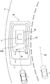
Fig. 5 is an explanatory diagram of the speed distribution region 50 set for the preceding vehicle 3 in the vehicle control system 100 of the first embodiment when the vehicle 1 and the preceding vehicle 3 are located on a curved road 5 where the road curves during normal running. As shown in fig. 5, the speed distribution area 50 has a smaller allowable upper limit value of the relative speed as the lateral distance and the longitudinal distance from the preceding vehicle 3 are smaller (the closer to the preceding vehicle 3 is), similarly to the speed distribution area 40 set in the case of the straight road 2. Fig. 5 shows an equal relative velocity line connecting points having the same allowable upper limit value for ease of understanding. In the present embodiment, the equal relative speed lines d, e, and f correspond to the allowable upper limit value V, respectivelylimIs 0km/h, 20km/h and 40 km/h.
In such a speed distribution region 50, the allowable upper limit value VlimIs 0kmThe entry prohibition area 52 in which the vehicle 1 cannot enter the periphery of the preceding vehicle 3, that is, the vehicle 1 cannot approach the preceding vehicle 3 any further, is set inside the equal relative speed line d of/h. The entry prohibited area 52 is a substantially rectangular area set by the same method as the entry prohibited area 42 set when the preceding vehicle 3 is located on the straight road 2.
The front and rear edges of the constant relative speed lines d, e, f provided outside the speed distribution area 50 are arranged parallel to the lateral direction of the preceding vehicle 3, as are the front and rear edges of the constant relative speed lines a, b, c set in the case of the straight road 2. The front and rear length dimensions of the constant relative velocity lines d, e, and f are set in the same manner as the front and rear length dimensions of the constant relative velocity lines a, b, and c, and are disposed at positions that are bilaterally symmetrical with respect to the preceding vehicle 3. On the other hand, in the side region of the speed distribution region 50, the sides of the constant relative speed lines d, e, f are curved with a curvature corresponding to the curvature of the curved road 5, more specifically, with a curvature equal to the curvature of the curved road 5, so as to connect the front and rear end portions, respectively. The four corners of the constant relative speed lines d, e, and f are formed in an arc shape, similarly to the speed distribution region 40 set when the preceding vehicle 3 is located on the straight road 2. Therefore, both side regions of the speed distribution region 50 have curved regions where the equal relative speed lines a, b, c are curved in correspondence with the curvature of the curved road 5.
Here, the allowable upper limit value V of the relative speed enters the outside of the prohibited area 52limThe region inside the constant relative velocity line d of 0km/h is set as the allowable upper limit value V of the relative velocity between the vehicle 1 and the preceding vehicle 3limA relative velocity zero region 54 limited to 0 km/h. Therefore, the relative speed zero region 54 is a curved region, which is a region in which the front edge and the rear edge are parallel to the lateral direction of the preceding vehicle 3, and both side edges are curved with a curvature corresponding to the curvature of the curved road 5, more specifically, with a curvature equal to the curvature of the curved road 5.
The speed distribution regions 40 and 50 are not limited to the above calculation method, and may be set based on various parameters. Examples of the parameters include the relative speed between the vehicle 1 and the object, the type of the object, the traveling direction of the vehicle 1, the moving direction and moving speed of the object, the length of the object, and the absolute speed of the vehicle 1. That is, the coefficient k and the calculation formula can be selected based on these parameters.
The velocity distribution regions 40 and 50 can be set for various objects. Examples of the object include a vehicle, a pedestrian, a bicycle, a road divider, an obstacle, a traffic light, and a traffic sign. Vehicles can be classified as automobiles, trucks, motorcycles. The pedestrians can be classified into adults, children and crowds. The travel path partition includes a guardrail, a shoulder forming a step at an end of the travel path, a center separation zone, and a lane boundary line. The obstacles include ridges, furrows, pits, and falling objects. The traffic sign comprises a stop line and a stop sign.
Next, a process flow of the vehicle control system according to the present embodiment will be described with reference to fig. 6. Fig. 6 is a processing flow of the vehicle control apparatus. When the vehicle 1 travels on the traveling road, as shown in fig. 6, the ECU10 (data acquisition unit) of the vehicle 1 acquires various data from a plurality of sensors (S10). Specifically, the ECU10 acquires image data obtained by capturing an image of the front side of the vehicle 1 from the in-vehicle camera 21 and receives measurement data from the millimeter wave radar 22.
The ECU10 (object detection unit) processes data acquired from an external sensor including at least the in-vehicle camera 21 to detect an object (S11). Specifically, the ECU10 executes image processing of the image data and detects the preceding vehicle 3 as the object. At this time, the type of the object (in this case, a vehicle) is specified. Further, the ECU10 can detect the presence of a specific obstacle from the map information.
The ECU10 (position and relative speed calculation unit) calculates the position and relative speed of the detected object (the preceding vehicle 3) with respect to the vehicle 1 based on the measurement data. The position of the object includes a longitudinal position (longitudinal distance) along the traveling direction of the vehicle 1 and a lateral position (lateral distance) along a lateral direction orthogonal to the traveling direction. The relative velocity may be directly used as the relative velocity included in the measurement data, or a velocity component along the traveling direction may be calculated from the measurement data. The velocity component orthogonal to the traveling direction is not necessarily calculated, and can be estimated from a plurality of pieces of measured data and/or a plurality of pieces of image data, if necessary.
Further, the ECU10 (road curvature calculating unit) specifies a white line of the road based on the image data of the in-vehicle camera 21, and calculates the curvature of the road from the position of the white line.
The ECU10 (speed distribution region setting unit) sets the speed distribution regions 40 and 50 for the detected object (i.e., the preceding vehicle 3) based on the calculated curvature of the road (S12). Here, since the curvature of the road becomes 0 when the road is a straight line, a substantially rectangular speed distribution region 40 in which the curvature of the side of the constant relative speed lines a, b, and c shown in fig. 3 is 0 is set. In the case where the road curves, since the curvature of the road is a value other than 0, a speed distribution region 50 is set in which the curvatures of the sides of the constant relative speed lines d, e, f shown in fig. 5 are curved in the same manner as the curvature of the road. In other words, in either case, the side of the constant relative speed line of the speed distribution region is arranged with a curvature equal to the curvature of the road.
The ECU10 (path calculation section) calculates a path on which the vehicle 1 can travel and a set vehicle speed or target speed at each position on the path, based on the set speed distribution areas 40, 50 (S13). Then, the ECU10 (running control execution unit) executes running control so that the vehicle 1 runs on the calculated route (S14).
Since the processing flow of fig. 6 is executed at predetermined time intervals (for example, 0.1 second), the calculated route and the set speed on the route change with the passage of time.
Here, speed control of the vehicle 1 will be described in a case where the vehicle 1 approaches the preceding vehicle from behind the preceding vehicle 3 when the vehicle 1 and the preceding vehicle 3 travel on the curved road 5.
As shown by a path R1 in fig. 5, when the vehicle 1 approaches the preceding vehicle 3 from behind the preceding vehicle 3, the vehicle 1 travels so as to cross the equal relative speed lines f, e, and d of the speed distribution region 50. In this case, e.g. vehiclesWhen the vehicle 1 travels at 40km/h, the traveling speed can be maintained up to the constant relative speed line f, but the upper limit value V is allowed to exceed the constant relative speed line flimSince the vehicle speed gradually decreases, the vehicle control system 100 outputs a brake request signal to the brake control system 32 to decelerate the vehicle 1, and controls the vehicle 1 so as not to exceed the allowable upper limit value V set for the pointlim。
When the vehicle 1 reaches the outer edge of the relative speed zero region 54, the vehicle 1 is controlled so that the relative speed with the preceding vehicle 3 becomes 0 (zero). Therefore, the vehicle 1 does not approach the preceding vehicle 3 any further in the normal driving state.
However, for example, in the case where the preceding vehicle 3 decelerates unexpectedly, the vehicle 1 may enter the relative speed zero region 54. In this case, the vehicle control system 100 controls the vehicle 1 so that the vehicle 1 moves outside the relative speed zero region 54. More specifically, the vehicle control system 100 outputs the brake request signal so that the relative speed between the vehicle 1 and the preceding vehicle 3 becomes negative, that is, less than 0km/h, and moves the vehicle 1 away from the preceding vehicle 3.
When the vehicle 1 enters the relative speed zero region 54, the vehicle control system 100 controls the speed and/or the travel route of the vehicle 1 so that the vehicle 1 does not enter the entry prohibited region 52. That is, when controlling only the speed of the vehicle 1, the vehicle control system 100 determines the braking force of the vehicle 1 and outputs a braking request signal to the brake control system 32 so as not to exceed the rear boundary line 52B in order to allow the vehicle 1 to travel outside (behind) the rear boundary line 52B entering the prohibited area 52, as shown by a path R2 in fig. 5. As a result, the vehicle 1 is closest to the preceding vehicle 3 at a position outside the entrance prohibition area 52, but does not enter the entrance prohibition area 52 by approaching the preceding vehicle 3 any further.
Further, when the vehicle 1 enters the relative speed zero region 54, the vehicle control system 100 may not only decelerate the vehicle 1 and return to the rear of the rear boundary line 52B of the entrance prohibition region 52 as described above, but may also perform, for example, steering control in addition to speed control so as to avoid a collision with the preceding vehicle 3. In this case, the vehicle control system 100 may set the target travel route outside the entrance prohibition area 52, as shown by, for example, a route R3 in fig. 5.
On the other hand, as shown by the two-dot chain line in fig. 5, when the vehicle 1 travels in a lane near the lane where the preceding vehicle 3 is located, for example, in a lane on the right side, the vehicle 1 can be prevented from being subjected to the allowable upper limit value V of the speed distribution region 50 because the speed distribution region 50 set around the preceding vehicle 3 does not deviate from the lanelimRestricted from traveling in an adjacent lane (e.g., path R4).
According to the above embodiment, the following effects can be obtained.
Since the ECU10 sets the speed distribution regions 40 and 50 around the leading vehicle 3, the ECU10 can limit the allowable upper limit V for the relative speed between the leading vehicle 3 and the vehicle 1limSince the safe driving support system such as the automatic braking control and the steering assist control can be comprehensively controlled, the safe driving support can be provided by the simple and effective speed control.
When the preceding vehicle 3 is located on the curved road 5, the ECU10 sets the speed distribution region 50 having a curved region in a region lateral to the preceding vehicle 3, and in the curved region, the relative speed lines d, e, f are curved in accordance with the curvature of the curved road 5, so that the speed distribution region 50 can be prevented from deviating from the lane of the road on which the preceding vehicle 3 is located.
Here, for example, as shown by a two-dot chain line in fig. 3, if the speed distribution region 40 is set in the case where the road curves, as in the case of the straight road 2, a part of the speed distribution region 40, particularly one of the side regions, may exceed the lane boundary line of the road. At this time, if the vehicle 1 is traveling in a lane on the right side of the lane in which the preceding vehicle 3 is located, the traveling speed of the vehicle 1 is exceeded by the allowable upper limit value V of the preceding vehicle 3 set in the traveling lane of the vehicle 1limLimiting or altering the travel route. In particular, in the example of fig. 3, since the width of the relative speed lines a, b, and c is relatively narrow in the side region of the speed distribution region 40, the vehicle 1 is required to be suddenly decelerated or the course of the vehicle is required to be changed. Such traveling becomes an unintended deceleration or steering for the passenger of the vehicle 1 traveling on the adjacent lane of the preceding vehicle 3, and becomes a traveling support that feels uncomfortable.
In the present embodiment, when the road on which the preceding vehicle 3 is located is a curved road 5, since the relative speed lines d, e, f have curved regions that curve with a curvature equal to that of the curved road 5 in the region lateral to the preceding vehicle 3, that is, the region lateral to the speed distribution region 50, the speed distribution region 50 can be set according to the shape of the road, and the speed distribution region 50 can be prevented from extending to an adjacent lane. Furthermore, unnecessary deceleration or steering of the vehicle 1 traveling on an adjacent lane, for example, can thereby be avoided. Therefore, the vehicle control system 100 according to the present embodiment can provide driving support that allows the passenger to feel comfortable and safe.
Since the speed distribution regions 40 and 50 have the allowable upper limit value zero regions 44 and 54 and the vehicle entrance prohibition regions 42 and 52, the vehicle 1 keeps the relative speed with the preceding vehicle 3 at the position of the boundary line of the relative speed zero regions 44 and 54 at zero in the normal driving state. Therefore, the vehicle control system 100 can travel the vehicle 1 while keeping a predetermined distance from the preceding vehicle 3, and therefore can perform safe driving support.
Even when the vehicle 1 enters the relative speed zero regions 44 and 54 due to unexpected deceleration of the preceding vehicle 3 or the like and approaches the preceding vehicle 3, the vehicle control system 100 performs acceleration/deceleration/steering control on the vehicle 1 so that the vehicle 1 does not enter the prohibited regions 42 and 52, and therefore, a predetermined distance can be secured between the vehicle 1 and the preceding vehicle 3 when collision avoidance control is performed. Therefore, the passenger can be prevented from feeling uneasy, and safe driving support can be performed.
The entry prohibition areas 42 and 52 are set to change in accordance with the traveling speed Vp of the preceding vehicle 3, and more specifically, the entry prohibition areas 42 and 52 are set to expand as the traveling speed Vp of the preceding vehicle 3 increases. Here, it is known that, when a distance and a speed at which the passenger of the vehicle 1 feels safe and safe with respect to the preceding vehicle 3 are secured, the distance and the speed at which the passenger feels safe vary with the traveling speed Vp of the preceding vehicle. More specifically, if the traveling speed Vp of the preceding vehicle 3 becomes large, the driver of the vehicle 1 takes a larger distance with respect to the preceding vehicle 3 or travels at a smaller relative speed with respect to the preceding vehicle 3. Here, in the present embodiment, the entrance prohibition areas 42 and 52 are set so that the entrance prohibition areas 42 and 52 are enlarged as the traveling speed Vp of the preceding vehicle 3 increases, so that the distance and speed that meet the passenger feel can be ensured for the preceding vehicle 3, and the driving assistance that gives the passengers of the vehicle 1 a sense of peace and safety can be performed.
[ second embodiment ]
Next, a vehicle control system according to a second embodiment of the present invention will be described. The vehicle control system according to the second embodiment is similar to the vehicle control system according to the first embodiment except that the setting of the speed distribution region set around the stopped vehicle 6 is different when the object is the stopped vehicle 6.
Fig. 7 is a diagram of a speed distribution region 60 set for a stopped vehicle 6 in the vehicle control system 100 according to the second embodiment of the present invention. In the present embodiment, the stopped vehicle 6 is stopped at the end (left end) on the curved road 5. Therefore, the vehicle 1 traveling on the road 5 is located at a position laterally offset from the traveling direction (front-rear direction) of the stopped vehicle 6. When the vehicle 1 is deviated in the lateral direction with respect to the front-rear direction of the stopped vehicle 6, the ECU10 sets the speed distribution region 60 to have a curved region in which the constant relative speed line curves along the curve of the road only in the side region on the side closer to the vehicle 1 among the side regions of the speed distribution region 60 set to the sides of the stopped vehicle 6.
Here, if one of the side ends of the vehicle 1 (the left end in the example of fig. 7) is located at the other side end (the right end in the example of fig. 7) of the side ends of the stopped vehicle 6, or at a position further laterally displaced from the stopped vehicle 6 (the right position in the example of fig. 7), the ECU10 determines that the vehicle 1 is displaced from the stopped vehicle 6. When the center C of the vehicle 1 is located at a position on the side end (right end in the example of fig. 7) of the stopped vehicle 6 or at a position further laterally displaced from the stopped vehicle 6, the ECU10 may determine that the vehicle 1 is displaced from the stopped vehicle 6.
Similarly to the speed distribution region 50 of the first embodiment, the speed distribution region 60 has smaller allowable upper limit values of the relative speed as the lateral distance and the longitudinal distance from the stopped vehicle 6 are smaller (the closer to the stopped vehicle 6 is). Note that fig. 7 shows an equal relative velocity line connecting points having the same allowable upper limit value for ease of understanding. In the present embodiment, the equal relative velocity lines g, h, i correspond to the allowable upper limit value V, respectivelylimIs 0km/h, 20km/h and 40 km/h.
Here, the front, rear, and left sides of the constant relative velocity lines g, h, and i are arranged in the same manner as the front, rear, and left sides of the constant relative velocity lines a, b, and c of the velocity distribution region 40 of the first embodiment, respectively. On the other hand, the side closer to the vehicle 1 among the sides of the constant relative velocity lines g, h, i, that is, the right side of the constant relative velocity lines g, h, i in the example of fig. 7, is curved with a curvature corresponding to the curvature of the curved road 5, more specifically, with a curvature equal to the curvature of the curved road 5, in the same manner as the velocity distribution region 50 of the first embodiment, so that the front and rear end portions are connected to each other. Therefore, one side region of the speed distribution region 60 has a curved region in which the equal relative speed lines g, h, i are curved in correspondence with the curvature of the curved road 5.
In the velocity distribution region 60, the allowable upper limit value V is set tolimAn entrance prohibition area 62 similar to the first embodiment is set around the leading vehicle 3 inside the constant relative speed line g of 0km/h, and the allowable upper limit value V of the relative speed enters the outside of the prohibition area 62limThe region inside the constant relative velocity line g of 0km/h is set as the allowable upper limit value V of the relative velocity between the vehicle 1 and the stopped vehicle 6limA relative velocity zero region 64 limited to 0 km/h. Thus, the relative velocity zero region 64 also has a curved region where one side region is locatedThe equal relative speed line g of the domain is curved corresponding to the curvature of the curved road 5.
In the vehicle control system of the second embodiment, when the vehicle 1 is at a position laterally offset from the front-rear direction of the stopped vehicle 6, the ECU10 calculates the set vehicle speed or the target speed (for example, the path R5 in fig. 7) on the route on which the vehicle 1 can travel and at each position on the route based on the speed distribution region 60 set around the stopped vehicle 6, and performs the travel control so that the vehicle 1 travels on the calculated route, as in the first embodiment.
According to the vehicle control system of the present embodiment configured as described above, the following effects can be obtained.
When the vehicle 1 is deviated in the lateral direction with respect to the front-rear direction of the stopped vehicle 6, the ECU10 sets a curved region where the constant relative velocity lines g, h, i are curved only in a region on the side closer to the vehicle 1 among the side regions where the vehicle 6 is stopped, that is, the side regions of the velocity distribution region 60, and sets the velocity distribution region 60 in a region on the side away from the vehicle 1 on the opposite side so that the constant relative velocity lines g, h, i are linear. Here, in the case where the vehicle 1 is deviated in the lateral direction with respect to the stopped vehicle 6, that is, in the present embodiment, in the case where the vehicle 1 is deviated in the right direction with respect to the stopped vehicle 6, the possibility that the vehicle 1 approaches the right side of the stopped vehicle 6 is higher than the possibility that the vehicle approaches the left side of the stopped vehicle 6. Here, in the present embodiment, the speed distribution region 60 is set so as to have a curved region in which the equal relative speed lines g, h, i curve in accordance with the curvature of the road, only in the region closer to the right side of the vehicle 1, out of the regions on the side where the vehicle 6 is stopped, so that the speed distribution region 60 corresponding to the shape of the road is set only in the region where the vehicle 1 is highly likely to actually approach, and therefore the calculation process for setting the speed distribution region 60 can be simplified. Therefore, safe and safe driving support can be realized by simple processing of the speed distribution region 60.
[ third embodiment ]
Next, a vehicle control system according to a third embodiment of the present invention will be described. The vehicle control system according to the third embodiment is the same as the vehicle control system according to the first embodiment except that when the preceding vehicle is located on a curved road, the setting of the speed distribution region set around the preceding vehicle is different.
Fig. 8 is an explanatory diagram of a speed distribution region 70 set for the preceding vehicle 3 in the vehicle control system 100 according to the third embodiment in the case where the vehicle 1 and the preceding vehicle 3 are located on a curved road 5 in which the road curves during normal running. As shown in fig. 8, the speed distribution area 70 is similar to the speed distribution area 40 set in the case of the straight road 2 in that the smaller the lateral distance and the longitudinal distance from the preceding vehicle 3 (the closer to the preceding vehicle 3), the smaller the allowable upper limit value of the relative speed. Fig. 8 shows an equal relative velocity line connecting points having the same allowable upper limit value for ease of understanding. In the present embodiment, the equal relative speed lines j, k, and l correspond to the allowable upper limit value V, respectivelylimIs 0km/h, 20km/h and 40 km/h.
In such a speed distribution region 70, the allowable upper limit value VlimThe vehicle 1 cannot enter the periphery of the preceding vehicle 3 inside the equal relative speed line j of 0km/h, that is, the entry prohibited area 72 where the vehicle 1 cannot approach the preceding vehicle 3 any further is set. The entry prohibition area 72 is a substantially rectangular area set by the same method as the entry prohibition area 42 set when the preceding vehicle 3 is located on the straight road 2.
Further, the allowable upper limit value VlimThe front and rear edges of the constant relative velocity line j and the constant relative velocity lines k, l of 0km/h are arranged parallel to the lateral direction of the preceding vehicle 3, as are the front and rear edges of the constant relative velocity lines a, b, c set in the case of the straight road 2. The front and rear length dimensions of the constant relative velocity lines j, k, and l are set in the same manner as the front and rear length dimensions of the constant relative velocity lines a, b, and c, and are disposed at positions that are bilaterally symmetric with respect to the preceding vehicle 3. On the other hand, in the side regions on both sides of the velocity distribution region 70, the side edges of the constant relative velocity lines j, k, l are prohibited from entering the regionFront boundary line 72A of region 72 is located at a portion j further forward1、k1、l1And a portion j rearward of the rearward boundary line 72B2、k2、l2Curved with a curvature corresponding to that of the curved road 5, more specifically with a curvature equal to that of the curved road 5. Therefore, in both side regions of the speed distribution region 70, curved regions are set in which the relative speed lines j, k, l are curved in accordance with the curvature of the curved road 5, such as in front of and behind the entrance prohibition region 72. The side edges of the constant relative velocity lines j, k, l are located at the sides of the no entry region 72, that is, at a portion j located rearward of the front boundary line 72A of the no entry region 72 and forward of the rear boundary line 72B3、k3、l3The side boundary line 72C along the entrance prohibition region, more specifically, the side boundary line 72C extends linearly in parallel. The four corners of the constant relative speed lines j, k, l are formed in an arc shape, similarly to the speed distribution region 40 set when the preceding vehicle 3 is located on the straight road 2.
Here, the upper limit value V of the relative speed enters the outside of the prohibited area 72limThe region inside the constant relative velocity line j of 0km/h is set as the allowable upper limit value V of the relative velocity between the vehicle 1 and the preceding vehicle 3limA relative velocity zero region 74 limited to 0 km/h. Therefore, the areas on both sides of the relative velocity zero area 74 are also set with curved areas in front of and behind the entrance prohibition area 72.
The entry prohibition area 72 is enlarged as the traveling speed Vp of the preceding vehicle 3 is increased, but in this case, the constant relative speed line j is set3、k3、l3The longitudinal length or the lateral position also changes with the enlargement of the entrance prohibition area 72.
In the vehicle control system 100 having such a configuration, the ECU10 (speed distribution region setting unit) sets the speed distribution regions 40 and 70 for the detected object (i.e., the preceding vehicle 3) based on the calculated curvature of the road. Here, when the road is a straight line, the curvature of the road is 0, so the first embodiment is set as shown in fig. 3A substantially rectangular velocity distribution region 40 having a side edge curvature of 0 in the constant relative velocity lines a, b, and c. In addition, since the curvature of the road is a value other than 0 when the road is curved, a portion j before and after the entrance prohibition area 72 among the sides having the equal relative speed lines j, k, l as shown in fig. 8 is set1、k1、l1、j2、k2、l2A velocity distribution region 70 of the curved bend region. That is, in either case, on the side of the constant relative speed line of the speed distribution region 40, 70, the portions before and after the no- entry regions 52, 72 are arranged corresponding to the curvature of the road, and the portions on the side of the no- entry regions 52, 72 are arranged parallel to the side boundary lines 52C, 72C of the no- entry regions 52, 72.
Similarly to the first embodiment, the ECU10 sets a route in which the vehicle 1 approaches the preceding vehicle 3 from behind the preceding vehicle 3, such as the route R6 in fig. 8, sets a route in which the vehicle 1 travels outside (behind) the rear boundary line 52B of the entry prohibition area 52 and does not exceed the rear boundary line 52B, such as the route R7 in fig. 8, and sets a route in which speed control and steering control are performed so as to avoid a collision with the preceding vehicle 3, such as the route R8 in fig. 8.
Further, as shown by the two-dot chain line in fig. 8, when the vehicle 1 travels in a lane near the lane where the preceding vehicle 3 is located, for example, in a lane on the right side, since the speed distribution region 70 set around the preceding vehicle 3 does not deviate from the lane, the vehicle 1 is not subjected to the allowable upper limit value V of the speed distribution region 70limAnd (4) limiting the vehicle to be able to travel on an adjacent lane (for example, a route R9).
According to the above embodiment, the following effects can be obtained.
When the preceding vehicle 3 is located on the curved road 5, the ECU10 sets the speed distribution region 70 in a region lateral to the preceding vehicle 3, and the speed distribution region 70 has a curved region in which the relative speed lines j, k, l are curved in accordance with the curvature of the curved road 5 before and after entering the prohibited region 72, so that the speed distribution region 70 can be prevented from deviating from the lane of the road on which the preceding vehicle 3 is located.
On the other hand, when the preceding vehicle 3 is located on the curved road 5, the ECU10 sets the speed distribution region 70 in a region lateral to the preceding vehicle 3, and in this speed distribution region 70, the constant relative speed lines j, k, l are linear in parallel to the lateral boundary line 72C of the entrance prohibition region 72 on the lateral side of the entrance prohibition region 72, and therefore, in the region lateral to the preceding vehicle 3, a predetermined distance is maintained between the constant relative speed lines j, k, l and the lateral boundary line 72C of the entrance prohibition region 72.
Here, a problem assumed when the road on which the preceding vehicle 3 is located is curved will be described. For example, as shown in the first embodiment, if the constant relative velocity lines d, e, f are curved in accordance with the curve of the road in the side region of the velocity distribution region 50, the constant relative velocity lines d, e, f may enter the entry prohibition region 52 due to the position on the road of the preceding vehicle 3, the curvature of the curve of the road, or the like, and the constant relative velocity lines d, e, f cannot be set. Further, if the constant relative velocity lines d, e, f are curved in accordance with the curve of the road, the intervals of the constant relative velocity lines d, e, f may be particularly small on the sides of the entry prohibition area 52. In this case, if the vehicle 1 approaches the preceding vehicle 3 from the side, the vehicle 1 may be required to be decelerated abruptly or a course of the vehicle may be required to be changed.
In this embodiment, in this case, the region lateral to the preceding vehicle 3, that is, the region lateral to the velocity distribution region 70 has the constant relative velocity line j before and after the entrance into the prohibited region 721、k1、l1、j2、k2、l2By setting the speed distribution region 70 in accordance with the shape of the road in the curved region curved with the same curvature as that of the curved road 5, the speed distribution region 70 can be prevented from protruding to the adjacent lane.
On the other hand, in the side region of the velocity distribution region 70, the equal-phase relative velocity line j that enters the side of the prohibited region 723、k3、l3Is set in parallel with the side boundary line 72C of the entrance prohibition region 72, thereby preventing the equal relative velocity line j3、k3、l3The approach is too close to the entrance prohibition area 72, and a predetermined distance is secured between the entrance prohibition area 72 and the equal relative speed lines j, k, and l.
As described above, the equal relative speed lines j, k, l are set parallel to the entrance prohibition area 72 on the side of the entrance prohibition area 72, and the curved areas having the curvature equal to the curvature of the curved road 5 are set before and after the entrance prohibition area 72, so that unnecessary deceleration or turning of the vehicle 1 traveling on the adjacent lane, for example, can be avoided, and sudden deceleration or turning when the vehicle 1 approaches the preceding vehicle 3 from the side can also be avoided. Therefore, the vehicle control system 100 according to the present embodiment can provide driving support that allows the passenger to feel comfortable and safe.
[ fourth embodiment ]
Next, a vehicle control system according to a fourth embodiment of the present invention will be described. The vehicle control system according to the fourth embodiment is the same as the vehicle control system according to the third embodiment except that the setting of the speed distribution region set around the stopped vehicle 6 is different when the object is the stopped vehicle 6.
Fig. 9 is a diagram of a speed distribution region 76 set for a stopped vehicle 6 in the vehicle control system 100 according to the fourth embodiment of the present invention. In the present embodiment, the stopped vehicle 6 is stopped at the end (left end) on the curved road 5. Therefore, the vehicle 1 traveling on the road 5 is at a position laterally offset from the traveling direction (front-rear direction) of the stopped vehicle 6. In the case where the vehicle 1 is deviated in the lateral direction with respect to the front-rear direction of the stopped vehicle 6, the ECU10 sets the speed distribution region 76 only in the side region on the side closer to the vehicle 1 among the side regions of the speed distribution region 76 set to the sides of the stopped vehicle 6, and in this speed distribution region 76, the constant relative speed line curves along the entrance prohibition region 78 on the side of the entrance prohibition region 78 and along the curve of the road before and after the entrance prohibition region 78.
Here, the ECU10 determines that the vehicle 1 is offset with respect to the stopped vehicle 6 when one of the side ends (the left end in the example of fig. 9) of the vehicle 1 is at the position of the other side end (the right end in the example of fig. 9) of the side ends of the stopped vehicle 6, or at a position further offset in the lateral direction from the stopped vehicle 6 than that (the right position in the example of fig. 9). Further, the ECU10 may determine that the vehicle 1 is offset with respect to the stopped vehicle 6 when the center C of the vehicle 1 is at a position at the side end (the right end in the example of fig. 9) where the vehicle 6 is stopped, or at a position further laterally offset from the stopped vehicle 6.
Similarly to the speed distribution region 50 of the first embodiment, the speed distribution region 76 has smaller allowable upper limit values of the relative speed as the lateral distance and the longitudinal distance from the stopped vehicle 6 are smaller (the closer to the stopped vehicle 6 is). Note that fig. 9 shows an equal relative velocity line connecting points having the same allowable upper limit value for ease of understanding. In the present embodiment, the equal relative velocity lines m, n, and o correspond to the allowable upper limit value V, respectivelylimIs 0km/h, 20km/h and 40 km/h.
In such a speed distribution region 76, the allowable upper limit value VlimAn entrance prohibition area 52 similar to the first embodiment is set around the leading vehicle 3 inside the constant relative speed line m of 0km/h, and the allowable upper limit value V of the relative speed enters the outside of the prohibition area 52limThe region inside the constant relative velocity line m of 0km/h is set as the allowable upper limit value V of the relative velocity between the vehicle 1 and the stopped vehicle 6limLimited to a relative velocity zero region 80 of 0 km/h.
Here, the front, rear, and left sides of the constant relative velocity lines m, n, and o are arranged in the same manner as the front, rear, and left sides of the constant relative velocity lines a, b, and c of the velocity distribution region 40 of the first embodiment, respectively. On the other hand, of the sides of the constant relative velocity lines m, n, o, the side closer to the vehicle 1, that is, the right side of the constant relative velocity lines m, n, o in the example of fig. 9, in the same manner as the velocity distribution region 70 of the third embodiment, a curved region in which the constant relative velocity lines m, n, o are curved with a curvature corresponding to the curvature of the curved road 5, more specifically, with a curvature equal to the curvature of the curved road 5, is formed before and after the entrance prohibition region 78, and is arranged along the entrance prohibition region 78, more specifically, parallel to the side boundary line 78C, on the side of the entrance prohibition region 78.
In the vehicle control system of the second embodiment, when the vehicle 1 is at a position laterally offset from the front-rear direction of the stopped vehicle 6, the ECU10 calculates the set vehicle speed or the target speed (for example, the path R10 in fig. 9) on the path on which the vehicle 1 can travel and at each position on the path based on the speed distribution region 76 set around the stopped vehicle 6, and performs the travel control so that the vehicle 1 travels on the calculated path, as in the first embodiment.
According to the vehicle control system of the present embodiment configured as described above, the following effects can be obtained.
When the vehicle 1 is deviated in the lateral direction with respect to the front-rear direction of the stopped vehicle 6, the ECU10 is set such that the relative velocity lines m, n, o curve in the front-rear direction of the entrance prohibition area 78 and the relative velocity lines m, n, o are parallel to the side boundary line 78C of the entrance prohibition area 78 only in the side area of the stopped vehicle 6, that is, in the side area of the velocity distribution area 76 on the side closer to the vehicle 1. In a region on the side away from the vehicle 1, a velocity distribution region 76 is set such that the equal relative velocity lines m, n, and o are linear. Here, in the case where the vehicle 1 is deviated in the lateral direction with respect to the stopped vehicle 6, that is, in the present embodiment, in the case where the vehicle 1 is deviated in the right direction with respect to the stopped vehicle 6, the vehicle 1 is more likely to approach the right side of the stopped vehicle 6 than the left side of the stopped vehicle 6. Here, in the present embodiment, the speed distribution region 76 is set so that the relative speed lines m, n, o before and after entering the prohibited region 78 curve in accordance with the curvature of the road only in the region closer to the right side of the vehicle 1 among the regions on the side where the vehicle 6 is stopped, and the like, so the speed distribution region 76 corresponding to the shape of the road is set only in the region where the vehicle 1 is more likely to actually approach, and therefore the calculation process for setting the speed distribution region 76 can be simplified. Therefore, safe and safe driving support can be realized by simple processing of the speed distribution region 76.
[ fifth embodiment ]
Next, a local vehicle control system according to a fifth embodiment of the present invention will be described. The vehicle control system according to the fifth embodiment is the same as the vehicle control system according to the first embodiment except that the setting of the speed distribution region when the vehicle 1 passes over the preceding vehicle 3 is different from the vehicle control system according to the first embodiment.
Fig. 10 is a diagram of a speed distribution area 82 set for the preceding vehicle 3 in the fifth embodiment of the present invention, and is a diagram of the speed distribution area 82 in a case where the preceding vehicle 3 travels on a straight road. Fig. 11 is a diagram of a speed distribution region 88 set for the preceding vehicle 3 in the fifth embodiment of the present invention, and is a diagram of the speed distribution region 88 when the preceding vehicle 3 travels on a curved road. As described above, the speed distribution regions 82 and 88 of the fifth embodiment include the overtaking speed distribution regions 86 and 92 set when the vehicle 1 overtakes the preceding vehicle 3, in addition to the entry prohibited regions 42 and 52 similar to the first embodiment.
First, as shown in fig. 10, when the road is a straight road, the speed distribution area 82 is set to be straight along the direction in which the road extends. The passing speed distribution area 86 of the speed distribution area 82 is set in front of the vehicle 1, more specifically, in front of the entry prohibition area 42, and defines an allowable lower limit value V of the relative speed of the vehicle 1 with respect to the preceding vehicle 3 in the traveling direction of the vehicle 1minDistribution of (2). The passing speed distribution area 86 is set to have the same width as the no entry area 42 from the front boundary line 42A of the no entry area 42 to the front, and the lower limit value V is allowed as the distance from the preceding vehicle 3 in the front-rear direction (longitudinal direction) is smallerminThe larger the setting. In fig. 10, for ease of understanding, it is shown that the same allowable lower limit value V will be presentminThe constant relative velocity lines p, q, r, s, t connected by the points (A) and (B). These constant relative velocity lines p, q, r, s, and t extend obliquely toward the center in the width direction and toward the front side. In the present embodiment, the constant relative velocity lines p, q, r, s, t are, for example, minutesIs equivalent to the allowable lower limit value Vmin50km/h, 40km/h, 30km/h, 20km/h, 10 km/h.
As shown in fig. 11, when the road is a curved road, the speed distribution area 88 is set to be curved along the direction in which the road extends. The passing speed distribution region 92 of the speed distribution region 88 is set in front of the vehicle 1, more specifically, in front of the entry prohibition region 52, similarly to the passing speed distribution region 86 of the speed distribution region 82 set when the road is a straight line, and the lower limit value V is allowed as the distance from the preceding vehicle 3 in the front-rear direction (longitudinal direction) is smallerminThe larger the setting. In fig. 11, for ease of understanding, it is shown that the same allowable lower limit value V will be presentminThe constant relative velocity lines u, v, w, x, y connected to the point(s) of (a). Both side edges of these equal relative speed lines u, v, w, x, y are curved along the direction in which the road extends, more specifically, with a curvature equal to the curvature of the curve of the road. Therefore, the regions on both sides of the passing speed distribution region 92 of the speed distribution region 88 have curved regions in which the equal relative speed lines u, v, w, x, y curve in accordance with the curvature of the curved road 5. The constant relative velocity lines u, v, w, x, and y extend obliquely toward the center in the width direction and toward the front side. In the present embodiment, the constant relative velocity lines u, V, w, x, and y correspond to, for example, the allowable lower limit value Vmin50km/h, 40km/h, 30km/h, 20km/h, 10 km/h.
The vehicle control system 100 of the present embodiment configured as described above sets the speed distribution regions 40 and 50 around the preceding vehicle 3 in the same manner as the first embodiment when the vehicle 1 is located behind the preceding vehicle 3. When the vehicle 1 catches up with or exceeds the preceding vehicle 3, the vehicle control system 100 calculates a set vehicle speed or a target speed at each position on a route on which the vehicle 1 can travel and the route based on the speed distribution areas 40 and 50. Then, the ECU10 executes the travel control to cause the vehicle 1 to travel on the calculated route.
If the vehicle 1 passes by the side of the preceding vehicle 3 and moves to the front of the preceding vehicle 3, the vehicle control system 100 changes the speed distribution region set for the preceding vehicle 3 from the speed distribution regions 40, 50 to the speed distribution regions 82, 88. In the present embodiment, the vehicle 1 recognizes the center C as a point, and therefore, when the point at the center is located forward beyond the position of the front end of the preceding vehicle 3 in the traveling direction of the vehicle 1, it is determined that the vehicle 1 has moved forward of the preceding vehicle 3. The ECU10 may determine that the vehicle 1 has moved forward of the preceding vehicle 3 when the front end of the vehicle 1 reaches the front end of the preceding vehicle 1, or may determine that the vehicle 1 has moved forward of the preceding vehicle 3 when the rear end of the vehicle 1 reaches the front end of the preceding vehicle 1.
Here, when the ECU10 sets the speed distribution regions 82 and 88, since the curvature of the road becomes 0 when the road is a straight line, the speed distribution region 82 is set in which the curvature of the side of the equal relative speed lines p, q, r, s, and t shown in fig. 10 becomes 0. In the case where the road curves, the curvature of the road becomes a value other than 0, a speed distribution region 88 having a curved region shown in fig. 11 is set, and the speed distribution region 88 is curved so that the curvatures of the sides of the constant relative speed lines u, v, w, x, and y become equal to the curvature of the road. That is, in either case, the side of the constant relative speed line of the speed distribution region is arranged with a curvature equal to the curvature of the road.
When the vehicle 1 overtakes, the vehicle control system 100 calculates a route on which the vehicle 1 can travel when moving ahead of the preceding vehicle 3 and a set vehicle speed or target speed (for example, a route R11 in fig. 10 or a route R12 in fig. 11) at each position on the route, based on the overtaking speed distribution areas 82 and 88, so that the travel speed of the vehicle 1 does not exceed the allowable lower limit value V set in the overtaking speed distribution areas 82 and 88min. Then, the ECU10 executes the running control so that the vehicle 1 runs on the calculated route.
According to the vehicle control system 100 of the present embodiment configured as described above, the following effects can be obtained.
When the vehicle 1 passes over the preceding vehicle 3, since the passing speed distribution regions 82 and 88 are set in front of the preceding vehicle 3 when the vehicle 1 moves in front of the preceding vehicle 3, when the vehicle 1 moves from the side to the front of the preceding vehicle 3 and enters in front of the preceding vehicle 3, the vehicle is controlled in accordance with the allowable lower limit value set in the passing speed distribution regions 82 and 88. Therefore, when the vehicle 1 passes over the preceding vehicle 3, the driving speed and distance that the driver feels safe can be secured for the preceding vehicle 3, and therefore, the driving assistance that the driver feels safe can be performed.
In addition, in the case where the road is curved, the passing speed distribution region 92 is set to a curved region curved with a curvature equal to the curvature of the road, and the speed distribution region 88 is set along the curved road, so that the driving assistance of the vehicle 1 can be appropriately performed.
The present invention is not limited to the above embodiments, and may be, for example, the following embodiments.
The speed distribution region is not limited to being set over the entire circumference of the object, and may be set only in the front of the preceding vehicle, or only in the side or only in the rear, as in the fifth embodiment, for example. In short, the velocity distribution region may be set at least in a part of the periphery of the object.
In the first and third embodiments described above, the constant relative velocity lines of the velocity distribution region are set to be curved in the regions on both sides of the preceding vehicle 3, but in the second and fourth embodiments described above, the constant relative velocity lines of the velocity distribution region are set to be curved in one region where the vehicle 6 is stopped, and in short, when the road on which the object is located is curved with respect to the constant relative velocity lines of the velocity distribution region, the constant relative velocity lines may be set to be curved in at least one region on the side of the object.
The curved constant relative speed line is not limited to being set in an arc shape equal to the curvature of the road as in the above-described embodiment, and may be set so as to be curved as a whole in accordance with the curvature of the road, such as a curve derived by a predetermined calculation based on the curvature of the road, a continuous straight line, or the like.
In the second and fourth embodiments described above, the speed distribution regions 60 and 76 set so as to curve with respect to the constant speed line only in one of the side regions are set for the stopped vehicle 6, but not limited to this, for example, in the case where the vehicle is at a position laterally offset from the object in the front-rear direction with respect to another object such as a traveling vehicle, the speed distribution regions may be set so as to curve with respect to the constant speed line with respect to the curvature of the road only in the side region of the speed distribution region on the side close to the vehicle.
Description of symbols:
1 vehicle
2 straight line road
3 leading vehicle (object)
5 curved road
6 stop vehicle (object)
21 vehicle-mounted camera
22 millimeter wave radar
23 vehicle speed sensor
24 positioning system
25 navigation system
31 engine control system
32 brake control system
33 steering control system
40. 50, 60, 70, 76, 82, 88 velocity distribution area
42. 52, 62, 72, 78 enter the exclusion zone
44. 54, 64, 74, 80 relative velocity zero region
100 vehicle control system
a-s relative velocity curve
D0Safe distance
X pitch
Routes R1 to R12
Claims (10)
1. A vehicle control device mounted on a vehicle,
detecting an object in front of the vehicle,
setting a speed distribution region around the object, the speed distribution region defining a distribution of allowable upper limit values of a relative speed of the vehicle with respect to the object in a traveling direction of the vehicle,
performing travel control that suppresses the relative speed from exceeding the allowable upper limit value within the speed profile region,
the speed distribution region includes a plurality of relative speeds greater than zero, and is set such that the allowable upper limit value of the relative speed decreases as the distance from the object decreases, and that, when the road on which the object is located is a straight line, a constant relative speed line connecting points having the same allowable upper limit value is a straight line in a region lateral to the speed distribution region, and when the road on which the object is located is curved, a curved region is provided in a region lateral to the speed distribution region, and in this curved region, the front end and the rear end of the constant relative speed line are set at the same positions as when the constant relative speed line is a straight line, and the plurality of constant relative speed lines between the front end and the rear end are curved in accordance with the curvature of the road.
2. The vehicle control apparatus according to claim 1,
the speed distribution region is set to have the curved region only in the side region on a side close to the vehicle when the vehicle is at a position laterally offset with respect to a front-rear direction of the object.
3. The vehicle control apparatus according to claim 1,
the speed distribution region has an upper limit value permitted zero region in which the upper limit value permitted becomes zero at a position separated from the object by a predetermined distance, and has an entry prohibition region in which entry of the vehicle is prohibited at a position closer to the object than the relative speed zero region.
4. The vehicle control apparatus according to claim 2,
the speed distribution region has an upper limit value permitted zero region in which the upper limit value permitted becomes zero at a position separated from the object by a predetermined distance, and has an entry prohibition region in which entry of the vehicle is prohibited at a position closer to the object than the relative speed zero region.
5. The vehicle control apparatus according to claim 1,
the speed distribution area has an entrance prohibition area that prohibits the vehicle from entering at a position away from the object by a predetermined distance,
in the case where the road on which the object is located is curved, the equal relative speed line in the side region of the speed distribution region is set along the entrance-prohibited region on the side of the entrance-prohibited region, and the curved region is set before and after the entrance-prohibited region.
6. The vehicle control apparatus according to claim 2,
the speed distribution area has an entrance prohibition area that prohibits the vehicle from entering at a position away from the object by a predetermined distance,
in the case where the road on which the object is located is curved, the equal relative speed line in the side region of the speed distribution region is set along the entrance-prohibited region on the side of the entrance-prohibited region, and the curved region is set before and after the entrance-prohibited region.
7. The vehicle control apparatus according to claim 3,
the speed distribution area has an entrance prohibition area that prohibits the vehicle from entering at a position away from the object by a predetermined distance,
in the case where the road on which the object is located is curved, the equal relative speed line in the side region of the speed distribution region is set along the entrance-prohibited region on the side of the entrance-prohibited region, and the curved region is set before and after the entrance-prohibited region.
8. The vehicle control apparatus according to claim 4,
the entry prohibition area is set to be substantially rectangular,
when the road on which the object is located is curved, the constant relative velocity line in the side region of the velocity distribution region is set to be linear in parallel to the side boundary line of the entrance prohibition region on the side of the entrance prohibition region, and the curved region is set before and after the entrance prohibition region.
9. The vehicle control apparatus according to claim 4,
the entrance prohibition area is set to be larger as the moving speed of the object is higher.
10. The vehicle control apparatus according to claim 4,
when the vehicle is at a position laterally offset with respect to the front-rear direction of the object, the speed distribution region is set such that the constant relative speed line is set along the entry prohibition region on the side of the entry prohibition region and the curved region is set on the front-rear side of the entry prohibition region only in the side region on the side close to the vehicle.
Applications Claiming Priority (5)
| Application Number | Priority Date | Filing Date | Title |
|---|---|---|---|
| JP2016236024A JP6447963B2 (en) | 2016-12-05 | 2016-12-05 | Vehicle control device |
| JP2016-236024 | 2016-12-05 | ||
| JP2016-236023 | 2016-12-05 | ||
| JP2016236023A JP6447962B2 (en) | 2016-12-05 | 2016-12-05 | Vehicle control device |
| PCT/JP2017/043307 WO2018105524A1 (en) | 2016-12-05 | 2017-12-01 | Vehicle control apparatus |
Publications (2)
| Publication Number | Publication Date |
|---|---|
| CN110049909A CN110049909A (en) | 2019-07-23 |
| CN110049909B true CN110049909B (en) | 2022-05-03 |
Family
ID=62491124
Family Applications (1)
| Application Number | Title | Priority Date | Filing Date |
|---|---|---|---|
| CN201780075399.1A Active CN110049909B (en) | 2016-12-05 | 2017-12-01 | Vehicle control device |
Country Status (4)
| Country | Link |
|---|---|
| US (1) | US11180141B2 (en) |
| EP (1) | EP3549837A4 (en) |
| CN (1) | CN110049909B (en) |
| WO (1) | WO2018105524A1 (en) |
Families Citing this family (8)
| Publication number | Priority date | Publication date | Assignee | Title |
|---|---|---|---|---|
| JP6847885B2 (en) * | 2018-03-20 | 2021-03-24 | 株式会社東芝 | Information processing equipment, information processing methods and programs |
| JP2020050220A (en) * | 2018-09-28 | 2020-04-02 | ロベルト・ボッシュ・ゲゼルシャフト・ミト・ベシュレンクテル・ハフツングRobert Bosch Gmbh | Control device and control method |
| FR3093305B1 (en) * | 2019-02-28 | 2021-01-29 | Psa Automobiles Sa | REGULATING THE SPEED OF A VEHICLE WHEN OTHING IN A CORNER |
| US11410545B2 (en) * | 2019-07-19 | 2022-08-09 | Ford Global Technologies, Llc | Dynamic vehicle perimeter definition and reporting |
| JP7291162B2 (en) * | 2021-01-06 | 2023-06-14 | 本田技研工業株式会社 | VEHICLE CONTROL DEVICE, OPERATING METHOD AND PROGRAM OF VEHICLE CONTROL DEVICE |
| JP7645135B2 (en) * | 2021-06-08 | 2025-03-13 | 日立Astemo株式会社 | Driving support device |
| CN115923790A (en) * | 2021-07-28 | 2023-04-07 | 阿波罗智能技术(北京)有限公司 | Method, device and storage medium for vehicle speed limit control |
| CN115257780A (en) * | 2022-09-07 | 2022-11-01 | 一汽解放青岛汽车有限公司 | Method and device for determining vehicle speed under overtaking working condition |
Citations (7)
| Publication number | Priority date | Publication date | Assignee | Title |
|---|---|---|---|---|
| JP2010030425A (en) * | 2008-07-29 | 2010-02-12 | Nissan Motor Co Ltd | Traveling control device and traveling control method |
| JP2010095219A (en) * | 2008-10-20 | 2010-04-30 | Toyota Motor Corp | Device for controlling vehicle speed, method for controlling vehicle speed |
| CN102431552A (en) * | 2011-09-05 | 2012-05-02 | 北京航空航天大学 | Safe pre-warning device for anti-collision at rear of vehicle based on binocular stereo vision |
| DE102012006986A1 (en) * | 2012-04-05 | 2013-10-10 | Gm Global Technology Operations, Llc | Method for forecasting available traffic space for ego vehicle in highway and road, involves marking prohibited area adjacent to interference location as non-traffic space for ego vehicle, if interference is present |
| CN104369727A (en) * | 2013-08-12 | 2015-02-25 | 马自达汽车株式会社 | A braking device for a vehicle |
| WO2016024312A1 (en) * | 2014-08-11 | 2016-02-18 | 日産自動車株式会社 | Travel control device and method for vehicle |
| JP2016037149A (en) * | 2014-08-07 | 2016-03-22 | 日立オートモティブシステムズ株式会社 | Vehicle control system, and action plan system equipped with the same |
Family Cites Families (29)
| Publication number | Priority date | Publication date | Assignee | Title |
|---|---|---|---|---|
| JP3838048B2 (en) * | 2001-04-16 | 2006-10-25 | 日産自動車株式会社 | Vehicle travel control device |
| US8364366B2 (en) * | 2005-06-24 | 2013-01-29 | Deere & Company | System and method for providing a safety zone associated with a vehicle |
| JP4169065B2 (en) * | 2006-02-13 | 2008-10-22 | 株式会社デンソー | Vehicle control device |
| JP4893118B2 (en) * | 2006-06-13 | 2012-03-07 | 日産自動車株式会社 | Avoidance control device, vehicle including the avoidance control device, and avoidance control method |
| US8452464B2 (en) * | 2009-08-18 | 2013-05-28 | Crown Equipment Corporation | Steer correction for a remotely operated materials handling vehicle |
| JP4909849B2 (en) * | 2007-09-14 | 2012-04-04 | 本田技研工業株式会社 | Vehicle travel control device |
| US7979174B2 (en) * | 2007-09-28 | 2011-07-12 | Honeywell International Inc. | Automatic planning and regulation of the speed of autonomous vehicles |
| JP5385009B2 (en) * | 2009-05-29 | 2014-01-08 | 日立オートモティブシステムズ株式会社 | Vehicle control apparatus and vehicle control method |
| JP5554037B2 (en) | 2009-09-04 | 2014-07-23 | 本田技研工業株式会社 | Vehicle contact avoidance support device |
| JP5516301B2 (en) * | 2010-10-05 | 2014-06-11 | トヨタ自動車株式会社 | Vehicle runway determination system |
| JP5189157B2 (en) | 2010-11-30 | 2013-04-24 | 株式会社豊田中央研究所 | Moving object target state determination device and program |
| JP5656732B2 (en) | 2011-05-02 | 2015-01-21 | 株式会社デンソー | Collision probability computation device and collision probability computation program |
| JP2013056650A (en) * | 2011-09-09 | 2013-03-28 | Daimler Ag | Vehicle traveling control device |
| US9139201B2 (en) * | 2012-03-15 | 2015-09-22 | Toyota Jidosha Kabushiki Kaisha | Driving assist device |
| DE112012007124T5 (en) * | 2012-11-13 | 2015-07-23 | Toyota Jidosha Kabushiki Kaisha | Driver assistance device and driver assistance method |
| WO2014181434A1 (en) * | 2013-05-09 | 2014-11-13 | トヨタ自動車株式会社 | Driving assist system |
| DE102013013867A1 (en) * | 2013-08-20 | 2015-03-12 | Audi Ag | Motor vehicle and method for controlling a motor vehicle |
| JP6441610B2 (en) * | 2013-10-30 | 2018-12-19 | 株式会社デンソー | Travel control device and server |
| JP6057957B2 (en) * | 2013-10-30 | 2017-01-11 | 富士重工業株式会社 | Vehicle control device |
| KR101519287B1 (en) * | 2014-02-14 | 2015-05-11 | 현대자동차주식회사 | Apparatus and method for preventing vehicle collision |
| US9457807B2 (en) * | 2014-06-05 | 2016-10-04 | GM Global Technology Operations LLC | Unified motion planning algorithm for autonomous driving vehicle in obstacle avoidance maneuver |
| JP6160564B2 (en) * | 2014-06-09 | 2017-07-12 | マツダ株式会社 | diesel engine |
| JP6183298B2 (en) * | 2014-06-10 | 2017-08-23 | 株式会社デンソー | Collision avoidance device |
| JP6354440B2 (en) * | 2014-08-11 | 2018-07-11 | 日産自動車株式会社 | Travel control device and travel control method |
| WO2016024316A1 (en) * | 2014-08-11 | 2016-02-18 | 日産自動車株式会社 | Travel control device and method for vehicle |
| WO2016024318A1 (en) | 2014-08-11 | 2016-02-18 | 日産自動車株式会社 | Travel control device and method for vehicle |
| WO2016024313A1 (en) * | 2014-08-11 | 2016-02-18 | 日産自動車株式会社 | Travel control device and travel control method |
| JP6359986B2 (en) * | 2015-02-13 | 2018-07-18 | トヨタ自動車株式会社 | Vehicle driving support system |
| JP6269534B2 (en) * | 2015-03-02 | 2018-01-31 | トヨタ自動車株式会社 | Travel control device |
-
2017
- 2017-12-01 WO PCT/JP2017/043307 patent/WO2018105524A1/en not_active Ceased
- 2017-12-01 CN CN201780075399.1A patent/CN110049909B/en active Active
- 2017-12-01 EP EP17877847.8A patent/EP3549837A4/en not_active Withdrawn
- 2017-12-01 US US16/466,584 patent/US11180141B2/en active Active
Patent Citations (8)
| Publication number | Priority date | Publication date | Assignee | Title |
|---|---|---|---|---|
| JP2010030425A (en) * | 2008-07-29 | 2010-02-12 | Nissan Motor Co Ltd | Traveling control device and traveling control method |
| EP2305527A1 (en) * | 2008-07-29 | 2011-04-06 | Nissan Motor Co., Ltd. | Running control device, and running control method |
| JP2010095219A (en) * | 2008-10-20 | 2010-04-30 | Toyota Motor Corp | Device for controlling vehicle speed, method for controlling vehicle speed |
| CN102431552A (en) * | 2011-09-05 | 2012-05-02 | 北京航空航天大学 | Safe pre-warning device for anti-collision at rear of vehicle based on binocular stereo vision |
| DE102012006986A1 (en) * | 2012-04-05 | 2013-10-10 | Gm Global Technology Operations, Llc | Method for forecasting available traffic space for ego vehicle in highway and road, involves marking prohibited area adjacent to interference location as non-traffic space for ego vehicle, if interference is present |
| CN104369727A (en) * | 2013-08-12 | 2015-02-25 | 马自达汽车株式会社 | A braking device for a vehicle |
| JP2016037149A (en) * | 2014-08-07 | 2016-03-22 | 日立オートモティブシステムズ株式会社 | Vehicle control system, and action plan system equipped with the same |
| WO2016024312A1 (en) * | 2014-08-11 | 2016-02-18 | 日産自動車株式会社 | Travel control device and method for vehicle |
Also Published As
| Publication number | Publication date |
|---|---|
| EP3549837A1 (en) | 2019-10-09 |
| WO2018105524A1 (en) | 2018-06-14 |
| US20190389461A1 (en) | 2019-12-26 |
| EP3549837A4 (en) | 2020-07-29 |
| US11180141B2 (en) | 2021-11-23 |
| CN110049909A (en) | 2019-07-23 |
Similar Documents
| Publication | Publication Date | Title |
|---|---|---|
| CN110049909B (en) | Vehicle control device | |
| CN108290577B (en) | vehicle control device | |
| CN107792064B (en) | Vehicle control device | |
| CN110650877B (en) | Vehicle control device | |
| CN109843679B (en) | Vehicle control device | |
| JP6327708B2 (en) | Vehicle driving support device | |
| CN108012539B (en) | vehicle control device | |
| CN111433094A (en) | Vehicle control device | |
| JP6412346B2 (en) | Vehicle driving support device | |
| WO2018047232A1 (en) | Vehicle control device | |
| JP6447962B2 (en) | Vehicle control device | |
| JP6331233B2 (en) | Vehicle control device | |
| JP6447963B2 (en) | Vehicle control device | |
| JP6331234B2 (en) | Vehicle control device | |
| JP6347420B2 (en) | Vehicle control device |
Legal Events
| Date | Code | Title | Description |
|---|---|---|---|
| PB01 | Publication | ||
| PB01 | Publication | ||
| SE01 | Entry into force of request for substantive examination | ||
| SE01 | Entry into force of request for substantive examination | ||
| GR01 | Patent grant | ||
| GR01 | Patent grant |