CN108596976B - Method, device and equipment for relocating camera attitude tracking process and storage medium - Google Patents
Method, device and equipment for relocating camera attitude tracking process and storage medium Download PDFInfo
- Publication number
- CN108596976B CN108596976B CN201810394878.6A CN201810394878A CN108596976B CN 108596976 B CN108596976 B CN 108596976B CN 201810394878 A CN201810394878 A CN 201810394878A CN 108596976 B CN108596976 B CN 108596976B
- Authority
- CN
- China
- Prior art keywords
- image
- key frame
- frame image
- camera
- repositioning
- Prior art date
- Legal status (The legal status is an assumption and is not a legal conclusion. Google has not performed a legal analysis and makes no representation as to the accuracy of the status listed.)
- Active
Links
Images


Classifications
-
- G—PHYSICS
- G06—COMPUTING OR CALCULATING; COUNTING
- G06T—IMAGE DATA PROCESSING OR GENERATION, IN GENERAL
- G06T7/00—Image analysis
- G06T7/70—Determining position or orientation of objects or cameras
- G06T7/73—Determining position or orientation of objects or cameras using feature-based methods
- G06T7/74—Determining position or orientation of objects or cameras using feature-based methods involving reference images or patches
-
- G—PHYSICS
- G06—COMPUTING OR CALCULATING; COUNTING
- G06T—IMAGE DATA PROCESSING OR GENERATION, IN GENERAL
- G06T7/00—Image analysis
- G06T7/20—Analysis of motion
- G06T7/246—Analysis of motion using feature-based methods, e.g. the tracking of corners or segments
- G06T7/248—Analysis of motion using feature-based methods, e.g. the tracking of corners or segments involving reference images or patches
-
- G—PHYSICS
- G06—COMPUTING OR CALCULATING; COUNTING
- G06T—IMAGE DATA PROCESSING OR GENERATION, IN GENERAL
- G06T7/00—Image analysis
- G06T7/20—Analysis of motion
- G06T7/269—Analysis of motion using gradient-based methods
-
- G—PHYSICS
- G06—COMPUTING OR CALCULATING; COUNTING
- G06T—IMAGE DATA PROCESSING OR GENERATION, IN GENERAL
- G06T2207/00—Indexing scheme for image analysis or image enhancement
- G06T2207/10—Image acquisition modality
- G06T2207/10016—Video; Image sequence
-
- G—PHYSICS
- G06—COMPUTING OR CALCULATING; COUNTING
- G06T—IMAGE DATA PROCESSING OR GENERATION, IN GENERAL
- G06T2207/00—Indexing scheme for image analysis or image enhancement
- G06T2207/30—Subject of image; Context of image processing
- G06T2207/30244—Camera pose
Landscapes
- Engineering & Computer Science (AREA)
- Computer Vision & Pattern Recognition (AREA)
- Physics & Mathematics (AREA)
- General Physics & Mathematics (AREA)
- Theoretical Computer Science (AREA)
- Multimedia (AREA)
- Image Analysis (AREA)
- Studio Devices (AREA)
Abstract
The application discloses a repositioning method and device for a camera posture tracking process and a storage medium, and belongs to the field of augmented reality. The method comprises the following steps: acquiring a current image acquired after the ith marker image in the plurality of marker images; when the current image meets the repositioning condition, selecting a target key frame image from a key frame image library; the key frame image library stores image information of at least one key frame image, and the key frame image is an image which is cached in the camera attitude tracking process and successfully subjected to first relocation relative to other images; second repositioning the current image relative to the target keyframe image; and calculating to obtain a camera attitude parameter when the camera acquires the current image according to the positioning result of the first repositioning and the positioning result of the second repositioning.
Description
Technical Field
The embodiment of the application relates to the field of augmented reality, in particular to a repositioning method, a repositioning device, repositioning equipment and a storage medium in a camera posture tracking process.
Background
Visual SLAM (simultaneous Localization and mapping) refers to a technology of building an environment model in a motion process and estimating the motion of a subject carrying a camera without environment prior information. SLAM can be applied in the AR (Augmented Reality) field, the robot field, and the unmanned field.
Taking monocular vision SLAM as an example, the first frame image captured by the camera is usually taken as a marker image (Anchor). When the camera acquires the current image subsequently, the equipment tracks the common characteristic points between the current image and the marked image, and calculates the pose change of the camera in the real world according to the position change of the characteristic points between the current image and the marked image. However, in some scenes, the feature point in the current image is Lost (Lost), and the tracking cannot be continued. At this time, the current image needs to be repositioned using the SLAM repositioning method.
However, when tracking the camera pose in the AR (Augmented Reality) field, for example, in a scene of using a mobile phone to shoot a desktop for an AR game, because the scene specificity of the AR using scene exists, the effect of directly using the SLAM relocation method in the related art is poor, and a relocation solution suitable for the AR field still needs to be provided.
Disclosure of Invention
The embodiment of the application provides a relocation method, a relocation device, equipment and a storage medium in a camera posture tracking process, and can solve the problem that the effect of directly using an SLAM relocation method in the related technology in an AR use scene is poor. The technical scheme is as follows:
according to an aspect of the present application, there is provided a relocation method of a camera pose tracking process applied to a device having a camera for sequentially performing camera pose tracking of a plurality of marker images, the method comprising:
acquiring a current image acquired after the ith marker image in the plurality of marker images, wherein i is an integer greater than 1;
when the current image meets the repositioning condition, acquiring an initial feature point and an initial pose parameter of a first marker image in the plurality of marker images, wherein the initial pose parameter is used for indicating the camera posture when the camera acquires the first marker image;
carrying out feature point tracking on the current image relative to the first marked image to obtain a target feature point matched with the initial feature point;
calculating a pose change amount when the camera changes from the first camera pose to a target camera pose according to the initial feature points and the target feature points, wherein the target camera pose is a camera pose of the camera when the camera acquires the current image;
and repositioning to obtain target pose parameters corresponding to the target camera posture according to the initial pose parameters and the pose variation.
According to another aspect of the present application, there is provided a relocating device for a camera pose tracking process, for use in a device having a camera, the device being configured to perform camera pose tracking of a plurality of marker images in sequence, the device comprising:
the image acquisition module is used for acquiring a current image acquired after the ith marker image in the marker images, wherein i is an integer larger than 1;
an information acquisition module, configured to acquire an initial feature point and an initial pose parameter of a first marker image of the multiple marker images when the current image meets a repositioning condition, where the initial pose parameter is used to indicate a camera pose at which the camera acquires the first marker image;
a feature point tracking module, configured to perform feature point tracking on the current image with respect to the first marker image to obtain a target feature point matched with the initial feature point;
a variation calculating module, configured to calculate, according to the initial feature points and the target feature points, a pose variation when the camera changes from the first camera pose to a target camera pose, where the target camera pose is a camera pose of the camera when the current image is captured;
and the repositioning module is used for repositioning to obtain target pose parameters corresponding to the target camera posture according to the initial pose parameters and the pose variation.
According to another aspect of embodiments of the present application, there is provided an electronic device including a memory and a processor;
the memory has stored therein at least one instruction that is loaded and executed by the processor to implement the relocation method as described above.
According to another aspect of embodiments of the present application, there is provided a computer-readable storage medium having at least one instruction stored therein, the at least one instruction being loaded and executed by a processor to implement the relocation method as described above.
The technical scheme provided by the embodiment of the application has the following beneficial effects:
by relocating the current image and the key frame images in the key frame image library when the current image meets the relocation condition, the relocation can be realized in an Anchor-SLAM algorithm for tracking a plurality of continuous marked images, thereby reducing the possibility of interruption of the tracking process.
Drawings
In order to more clearly illustrate the technical solutions in the embodiments of the present application, the drawings needed to be used in the description of the embodiments are briefly introduced below, and it is obvious that the drawings in the following description are only some embodiments of the present application, and it is obvious for those skilled in the art to obtain other drawings based on these drawings without creative efforts.
FIG. 1 is a scene diagram of an AR application scenario provided by an exemplary embodiment of the present application;
FIG. 2 is a scene diagram of an AR application scenario provided by an exemplary embodiment of the present application;
FIG. 3 is a schematic diagram illustrating the principle of the Anchor-Switching AR System algorithm provided by an exemplary embodiment of the present application;
FIG. 4 is a block diagram of an electronic device provided in an exemplary embodiment of the present application;
FIG. 5 is a flow chart of a repositioning method for a camera pose tracking process provided by an exemplary embodiment of the present application;
FIG. 6 is a schematic diagram of a comparison of a first marker image, a current image, and a first order key frame image provided by an exemplary embodiment of the present application;
FIG. 7 is a flow chart of a relocation method provided by an exemplary embodiment of the present application;
FIG. 8 is a flow chart of a relocation method provided by an exemplary embodiment of the present application;
FIG. 9 is a flow chart of a relocation method provided by an exemplary embodiment of the present application;
FIG. 10 is a flow chart of a relocation method provided by an exemplary embodiment of the present application;
FIG. 11 is a flow chart of a relocation method provided by an exemplary embodiment of the present application;
FIG. 12 is a block diagram of a relocating device for a camera pose tracking process as provided by an exemplary embodiment of the present application;
fig. 13 is a block diagram of an electronic device provided in an exemplary embodiment of the present application.
Detailed Description
The present application will first be described in terms of several nouns:
AR (Augmented Reality): a technology for calculating the camera posture parameters of a camera in the real world (or called three-dimensional world, real world) in real time during the process of acquiring images by the camera and adding virtual elements on the images acquired by the camera according to the camera posture parameters. Virtual elements include, but are not limited to: images, video, and three-dimensional models. The goal of AR technology is to socket a virtual world on a screen for interaction over the real world. The camera attitude parameters comprise a displacement vector and a rotation matrix, wherein the displacement vector is used for representing the displacement distance of the camera in the real world, and the rotation matrix is used for representing the rotation angle of the camera in the real world.
For example, referring to fig. 1 and 2, the device adds an virtual character to the image captured by the camera. Along with the movement of the camera in the real world, the image shot by the camera changes, the shooting direction of the virtual character also changes, the effect that the virtual character stands still in the image is simulated, and the camera simultaneously shoots the image and the virtual character along with the change of the position and the posture, so that a real three-dimensional picture is presented for a user.
Anchor-Switching AR System: the AR system is used for determining camera attitude parameters in a natural scene based on camera attitude tracking of a plurality of marked images (anchors) connected, and then overlaying a virtual world on an image acquired by a camera according to the camera attitude parameters.
IMU (Inertial Measurement Unit): is a device for measuring the three-axis attitude angle (or angular rate) and acceleration of an object. Generally, an IMU includes three single-axis accelerometers and three single-axis gyroscopes, where the accelerometers are used to detect acceleration signals of an object on each coordinate axis in a three-dimensional coordinate system, and then calculate a displacement vector; and the gyroscope is used for detecting a rotation matrix of the object in a three-dimensional coordinate system. Optionally, the IMU includes a gyroscope, an accelerometer, and a geomagnetic sensor.
Schematically, the three-dimensional coordinate system is established in the following manner: 1. the X-axis is defined using the vector product Y X Z, pointing east in a direction tangential to the ground at the current location of the device; 2. the Y axis is at the current position of the equipment and points to the north pole of the geomagnetic field along the direction tangent to the ground; 3. the Z-axis points skyward and is perpendicular to the ground.
The application provides a relocation method suitable for an Anchor-Switching AR System algorithm. In the process of determining the camera posture, the Anchor-Switching AR System algorithm divides the motion process of the camera into at least two sections of tracking processes for tracking, and each section of tracking process corresponds to a respective marker image. Specifically, in the tracking process corresponding to the ith marker image, when the tracking effect of the current image relative to the ith marker image is worse than a preset condition (for example, the number of feature points that can be matched is less than a preset threshold), the last image of the current image is determined as the (i + 1) th marker image, and the (i + 1) th segment tracking process is started. Wherein i is a positive integer. Referring schematically to fig. 3, a schematic diagram of the principle of the Anchor-Switching AR System algorithm provided in an exemplary embodiment of the present application is shown. In the real world there is an object 320 and the device 340 provided with a camera is moved by being held in the hand of a user, during which a plurality of frame images 1-6 including the object 320 are taken. The device determines the image 1 as a 1 st mark image (born-anchor or born-image) and records initial pose parameters which can be acquired by an IMU (inertial measurement unit), then tracks the image 2 relative to the image 1 for feature points, and calculates the pose parameters of the camera when shooting the image 2 according to the initial pose parameters and the feature point tracking result; tracking the characteristic points of the image 3 relative to the image 1, and calculating the pose parameters of the camera when shooting the image 3 according to the initial pose parameters and the tracking results of the characteristic points; and tracking the characteristic points of the image 4 relative to the image 1, and calculating the pose parameters of the camera when shooting the image 4 according to the initial pose parameters and the tracking results of the characteristic points.
Then, feature point tracking is performed on the image 5 relative to the image 1, if the feature point tracking effect is worse than a preset condition (for example, the number of matched feature points is small), the image 4 is determined as a 2 nd marker image, feature point tracking is performed on the image 5 relative to the image 4, displacement variation of the camera between the shot images 4 and 5 is calculated, and then the pose parameter of the camera when the camera shoots the image 5 is calculated by combining the displacement variation of the camera between the shot images 4 and 1 and the initial pose parameter. And then, tracking the characteristic points of the image 6 relative to the image 4, and so on, if the tracking effect of the characteristic points of the current image is poor, determining the previous frame image of the current image as a new marked image, switching the new marked image, and then tracking the characteristic points again.
Alternatively, feature point tracking may employ an algorithm based on the visual odometry principle, such as feature point or direct methods. However, if the camera is in various abnormal scenes such as a relatively violent motion, a strong light source facing, and a white wall facing during the tracking process, the loss (Lost) phenomenon may occur during the above-mentioned Anchor-Switching AR System tracking process. The missing phenomenon means that enough feature points cannot be matched in the current image, so that the tracking fails.
Referring to fig. 4, a block diagram of an electronic device provided in an exemplary embodiment of the present application is shown. The apparatus comprises: a processor 420, a memory 440, a camera 460, and an IMU 480.
The processor 420 is electrically connected to the memory 440. Optionally, the processor 420 is connected to the memory 440 via a bus. Memory 440 stores one or more instructions, code segments and/or programs. The instructions, code segments and/or programs, when executed by the processor 420, are operable to implement a SLAM relocation method as provided in the following embodiments.
The processor 420 is also electrically connected to the camera 460. Optionally, the processor 420 is connected to the camera 460 by a bus. The camera 460 is a sensing device with image capture capability. The camera 460 may also be referred to by other names such as a camera, a light sensing device, and so on. The camera 460 has the capability to capture images continuously or multiple times. Optionally, the camera 460 is disposed inside the device or outside the device.
The processor 420 is also electrically connected to the IMU 480. Optionally, the IMU480 is configured to acquire pose parameters of the camera at predetermined time intervals, and record a timestamp of each set of pose parameters at the time of acquisition. The pose parameters of the camera include: a displacement vector and a rotation matrix. The rotation matrix acquired by the IMU480 is relatively accurate, and the acquired displacement vector may have a large error under the actual environment.
Referring to FIG. 5, a flow chart of a repositioning method of a camera pose tracking process provided in an exemplary embodiment of the present application is shown. The present embodiment is exemplified by the application of the repositioning method to the apparatus shown in fig. 4 for sequentially performing camera pose tracking of a plurality of marker images. The method comprises the following steps:
a camera in the equipment collects a frame of image according to a preset time interval to form an image sequence. Optionally, the camera acquires a frame of image forming image sequence at preset time intervals during the movement (translation and/or rotation).
Optionally, the device determines a first frame image (or one frame image meeting a predetermined condition in the previous frames of images) in the image sequence as a first marker image, performs feature point tracking on subsequently acquired images relative to the first marker image, and calculates a camera pose parameter of the camera according to a feature point tracking result; if the tracking effect of the feature points of the current frame image is worse than the preset condition, determining the previous frame image of the current frame image as a second marked image, tracking the feature points of the subsequently acquired image relative to the second marked image, calculating the camera attitude parameters of the camera according to the tracking result of the feature points, and so on. The device can perform camera pose tracking of successive marker images in sequence.
When the tracking process is in the ith tracking process corresponding to the ith marker image, the camera acquires the current image. The current image is a certain frame image acquired after the ith marker image, wherein i is an integer greater than 1.
the device will determine whether the current image meets the relocation condition. The relocation condition is used to indicate that the tracking process of the current image with respect to the i-th marker image has failed, or the relocation condition is used to indicate that the accumulated error in the historical tracking process has been higher than a preset condition.
In an optional embodiment, the device tracks the current image with respect to the ith marker image, and determines that the tracking process of the current image with respect to the ith marker image fails and meets the repositioning condition if there is no feature point in the current image that matches the ith marker image or the number of feature points in the current image that match the ith marker image is less than a first number.
In another alternative embodiment, the apparatus determines that the accumulated error in the history tracking process has become higher than the preset condition when the apparatus determines that the number of frames between the current image and the last repositioned image is larger than the second number, or determines that the accumulated error in the history tracking process has become higher than the preset condition when the apparatus determines that the number of marker images between the ith marker image and the first marker image is larger than the third number.
The content of the relocation condition in this embodiment is not limited.
When the current image meets the repositioning condition, the device attempts to perform feature point tracking on the current image relative to the first marker image. At this time, the device acquires initial feature points in the cached first marker image and initial pose parameters, wherein the initial pose parameters are used for indicating the camera posture when the camera acquires the first marker image.
Step 506, tracking the feature points of the current image relative to the first marked image to obtain target feature points matched with the initial feature points;
optionally, each set of matching feature point pairs includes two initial feature points and two target feature points that match each other.
The feature point tracking may use a tracking algorithm based on a visual odometer, which is not limited in this application. In one embodiment, feature point tracking employs the KLT (Kanade-Lucas) optical flow tracking algorithm; in another embodiment, the Feature point tracking uses SIFT (Scale-Invariant Feature Transform) algorithm-based extracted SIFT Feature descriptors and ORB (organized FAST and Rotated BRIEF) algorithm-extracted ORB Feature descriptors for Feature point tracking. The specific algorithm for tracking the feature points is not limited, and the feature point tracking process can adopt a feature point method or a direct method.
In one embodiment, the equipment extracts feature points of a first marked image to obtain N initial feature points; the equipment also extracts the feature points of the current image to obtain M candidate feature points; and then matching the M candidate characteristic points with the N initial characteristic points one by one to determine at least one group of matched characteristic point pairs. Each group of matching characteristic point pairs comprises: an initial feature point and a target feature point. The initial feature point is a feature point on the 1 st marked image, and the target feature point is a candidate feature point on the current image with the highest matching degree with the initial feature point.
Optionally, the number of initial feature points is greater than or equal to the number of target feature points. For example, the number of the initial feature points is 450, and the number of the target feature points is 320.
Step 508, calculating a pose variation amount when the camera changes from the initial pose parameter to the target pose parameter according to the initial feature points and the target feature points, wherein the target pose parameter is used for representing the pose of the camera when the camera collects the current image;
optionally, the device calculates a homography matrix homography between the two frames of images according to the initial feature points and the target feature points; decomposing the homography matrix homographiy to obtain the pose variation R when the camera changes from the initial pose parameter to the target pose parameterrelocalizeAnd Trelocalize。
The homography matrix describes a mapping relation between two planes, and if feature points in a natural scene (a real environment) all fall on the same physical plane, motion estimation can be performed through the homography matrix. When at least four pairs of matched initial characteristic points and target characteristic points exist, the equipment decomposes the homography matrix through ransac to obtain a rotation matrix RrelocalizeAnd translation vector Trelocalize。
Wherein R isrelocalizeIs a rotation matrix, T, of the camera as it changes from an initial pose parameter to a target pose parameterrelocalizeIs the displacement vector when the camera changes from the initial pose parameter to the target pose parameter.
And 510, repositioning to obtain target pose parameters according to the initial pose parameters and the pose variation.
And the equipment transforms the initial pose parameters by using the pose variation and then relocates the initial pose parameters to obtain target pose parameters, thereby calculating the camera pose of the camera when acquiring the current image.
In summary, according to the relocation method provided in this embodiment, when the current image meets the relocation condition, the current image and the first marker image are relocated, so that relocation can be implemented in the Anchor-Switching AR System algorithm that tracks a plurality of continuous marker images, thereby reducing the possibility of interruption of the tracking process, and solving the problem that the SLAM relocation method in the related art is not suitable for the post-variant SLAM algorithm.
In addition, since the repositioning process is to reposition the current image relative to the first marker image, which can be considered as being free of accumulated errors, the present embodiment can also eliminate accumulated errors generated by the tracking process of the plurality of marker images.
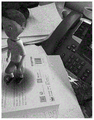
The repositioning method shown in fig. 5 is to reposition the current image corresponding to the first marker image, and in some scenarios, there is a possibility that the repositioning will fail. For example, when the difference between the shooting posture corresponding to the current image and the shooting posture of the first marker image is large, it may fail to directly match the current image and the first marker image to realize the relocation. Schematically, if the diagram (1) in fig. 6 is the first marker image and the diagram (2) in fig. 6 is the current image, the current image and the first marker image may fail to be directly repositioned because the overlapping area between the current image and the first marker image is too small to achieve a sufficient matching degree. In the embodiment of the present application, the diagram (3) in fig. 6 is introduced as a first-order key frame image, a rotation matrix and a translation vector are respectively calculated from a matching result of a current image with respect to the first-order key frame image and a matching result (repositioning result) of the first-order key frame image with respect to a first marker image, the two matching results are linked together by switching the marker images (the first-order key frame image is taken as one marker image), and then the rotation matrix and the translation vector of the current image with respect to the first marker image are obtained, so that repositioning is successful.
Referring to fig. 7, a flow chart of a repositioning method of a camera pose tracking process provided by another exemplary embodiment of the present application is shown. The present embodiment is exemplified by applying the relocation method to the apparatus shown in fig. 4. The device is used to perform camera pose tracking of multiple marker images in sequence. The method comprises the following steps:
a camera in the equipment collects a frame of image according to a preset time interval to form an image sequence. Optionally, the camera acquires a frame of image forming image sequence at preset time intervals during the movement (translation and/or rotation).
Optionally, the device determines a first frame image (or one frame image meeting a predetermined condition in the previous frames of images) in the image sequence as a first marker image, performs feature point tracking on subsequently acquired images relative to the first marker image, and calculates a camera pose parameter of the camera according to a feature point tracking result; if the tracking effect of the feature points of the current frame image is worse than the preset condition, determining the previous frame image of the current frame image as a second marked image, tracking the feature points of the subsequently acquired image relative to the second marked image, calculating the camera attitude parameters of the camera according to the tracking result of the feature points, and so on. The device can perform camera pose tracking of successive marker images in sequence.
When the tracking process is in the ith tracking process corresponding to the ith marker image, the camera acquires the current image. The current image is a certain frame image acquired after the ith marker image, wherein i is an integer greater than 1.
there may be more than one repositioning process in the camera pose tracking process. The device will pick some representative images from the images successfully relocated and save them as key frame images to the key frame image library. The key frame image library is a database for storing key frame images. The key frame image library stores image information of a plurality of key frame images. The image information includes: the image of the key frame image, the feature points in the key frame image and the first repositioning result corresponding to the key frame image. Optionally, the image information further comprises: and a first global descriptor of the key frame image, wherein the first global descriptor is used for representing the image characteristics of the key frame image in brief data quantity. Alternatively, the first global descriptor is used to uniquely represent image features of the key frame image in a brief amount of data.
The device will determine whether the current image meets the relocation condition. The relocation condition is used to indicate that the tracking process of the current image with respect to the i-th marker image has failed, or the relocation condition is used to indicate that the accumulated error in the historical tracking process has been higher than a preset condition.
In an optional embodiment, the device tracks the current image with respect to the ith marker image, and determines that the tracking process of the current image with respect to the ith marker image fails and meets the repositioning condition if there is no feature point in the current image that matches the ith marker image or the number of feature points in the current image that match the ith marker image is less than a first number.
In another alternative embodiment, the apparatus determines that the accumulated error in the history tracking process has become higher than the preset condition when the apparatus determines that the number of frames between the current image and the last repositioned image is larger than the second number, or determines that the accumulated error in the history tracking process has become higher than the preset condition when the apparatus determines that the number of marker images between the ith marker image and the first marker image is larger than the third number.
The content of the relocation condition in this embodiment is not limited.
When the current image meets the repositioning condition, the device picks out the target key frame image from the key frame image library. Optionally, the target key frame image is the image closest in distance from the image of the current image in the key frame image library. In different embodiments, the image distance can be characterized in any form of image similarity, image feature similarity, and a distance between matching feature points, which is not limited in this application.
In one embodiment, the device selects a target key frame image from a key frame image library through a similarity between a first global descriptor of the key frame image and a second global descriptor of a current image; in another embodiment, since the IMU is able to capture the reference pose parameters (which may be in error) at the time the camera captures the current image, the device picks the target keyframe image from the library of keyframe images by similarity between the first pose parameters of the keyframe image and the reference pose parameters of the current image.
after the device picks out the target key frame image in the key frame image library, the current image is repositioned relative to the target key frame image. Optionally, the relocation process includes the following steps:
1. acquiring key frame characteristic points of a target key frame image and a positioning result of first repositioning;
the key frame image library stores key frame feature points on each key frame image and a first camera pose tracking result. Optionally, the key frame feature points are characterized by SIFT feature descriptors or ORB feature descriptors. The positioning result of the first repositioning is a camera pose parameter (referred to as a key frame pose parameter for short) when the camera acquires the key frame image, or the first camera pose tracking result is a pose variation (a rotation matrix and a displacement vector) of the camera pose parameter when the camera acquires the key frame image relative to the camera pose parameter when the camera acquires the first marker image.
2. Carrying out feature point tracking on the current image relative to a target key image library to obtain target feature points matched with the key frame feature points;
optionally, each set of matching feature point pairs includes two mutually matching key frame feature points and target feature points.
The feature point tracking may use a tracking algorithm based on a visual odometer, which is not limited in this application. In one embodiment, feature point tracking employs the KLT (Kanade-Lucas) optical flow tracking algorithm; in another embodiment, the Feature point tracking uses SIFT (Scale-Invariant Feature Transform) algorithm-based extracted SIFT Feature descriptors and ORB (organized FAST and Rotated BRIEF) algorithm-extracted ORB Feature descriptors for Feature point tracking. The specific algorithm for tracking the feature points is not limited, and the feature point tracking process can adopt a feature point method or a direct method.
In one embodiment, since the target key frame image is an image that has been successfully repositioned, the device performs feature point extraction on the target key frame image to obtain N key frame feature points; the equipment also extracts the feature points of the current image to obtain M candidate feature points; and then matching the M candidate characteristic points with the N initial characteristic points one by one to determine at least one group of matched characteristic point pairs. Each group of matching characteristic point pairs comprises: one key frame feature point and one target feature point. The key frame feature points are feature points on a target key frame image, and the target feature points are candidate feature points on the current image, which have the highest matching degree with the key frame feature points.
Optionally, the number of key frame feature points is greater than or equal to the number of target feature points. For example, the number of key frame feature points is 480, and the number of target feature points is 350.
3. And calculating the pose variation of the camera when the camera changes from the key frame pose parameter to the target pose parameter according to the key frame feature points and the target feature points, wherein the target pose parameter is used for representing the camera pose of the camera when the camera collects the current image.
Optionally, the device calculates a homography matrix homography between the two frames of images according to the key frame feature points and the target feature points; decomposing the homography matrix homographiy to obtain the pose variation R when the camera changes from the key frame pose parameter to the target pose parametercmAnd Tcm。
Wherein R iscmIs the rotation matrix, T, of the camera as it changes from the keyframe pose parameter to the target pose parametercmIs the position of the camera as it changes from the key frame pose parameter to the target pose parameterAnd (4) moving the vector quantity.
And step 704, calculating to obtain a target posture parameter when the camera acquires the current image according to the positioning result of the first repositioning and the positioning result of the second repositioning.
Assume that the positioning result of the first relocation includes RmfAnd Tmf。RmfIs a rotation matrix, T, of the camera as it changes from initial pose parameters to keyframe pose parametersmfThe target attitude parameter when the camera acquires the current image is obtained by calculating the displacement vector when the camera changes from the initial attitude parameter to the key frame attitude parameter by adopting the following formula:

where R and T are target attitude parameters, SmfIs the scale from the first marker image to the target key frame image.
In summary, according to the repositioning method provided in this embodiment, when the current image meets the repositioning condition, the current image and the key frame image in the key frame image library are repositioned, and repositioning can be implemented in the Anchor-Switching AR System algorithm that tracks a plurality of continuous marker images, so that the possibility of interruption of the tracking process is reduced.
The keyframe images (keyframes) in the keyframe image library (keyframe Database) are gradually added and deleted throughout the camera pose tracking process. The key frame images are all images with successful repositioning. Optionally, the key frame image includes at least one of the following two images:
1. performing a first-order keyframe image for which the first repositioning was successful with respect to a first marker image of the plurality of marker images;
2. and carrying out the first repositioning on the successful n-order key frame images relative to the n-1-order key frame images in the key frame image library, wherein n is an integer larger than 1.
The calculation mode of the image global descriptor is as follows:
for the purpose of rapidly measuring the similarity between two images, the device may vectorize the images captured by the camera, and use a global descriptor to represent the features of the images. The global descriptor is used to represent feature information in an image with a brief amount of information. In the embodiment of the present application, the global descriptor of the key frame image is referred to as a first global descriptor, the global descriptor of the current image is referred to as a second global descriptor, and the global descriptor of the candidate image is referred to as a third global descriptor. The three global descriptors are calculated in the same manner, and the descriptions using the first, second, and third are only schematic illustrations.
In an alternative embodiment, a Bag of Words (Bag of Words) model is used to compute the global descriptor of the image. BoW is a concept often used in the field of natural language processing. Taking text as an example, an article may have ten thousand words, which may have only 500 different words, each of which occurs at different times. The word bag is like a single bag, and each bag contains the same words. This constitutes a representation of the text. This representation does not take into account grammatical and word order. In the field of computer vision, images are often expressed in terms of feature points and feature descriptors for the feature points. If the feature descriptor of the feature point is regarded as a word, a corresponding bag-of-words model can be constructed. With a BoW library (such as the open-source DBoW2 library), images can be conveniently converted to a low-dimensional vector representation. The similarity problem of two images is compared and correspondingly converted into the similarity problem of two vectors, and the method is essentially an information compression process.
The process of computing the image global descriptor is as follows, as shown in fig. 8:
the device also extracts m feature point descriptors in the image, m being a positive integer. The feature point descriptor is one of image feature points. Alternatively, the feature extraction algorithm used when the device extracts the feature points may be a FAST (Features from estimated Segment Test) Detection algorithm, a Shi-Tomasi (histones) Corner Detection algorithm, a Harris Corner Detection algorithm, a SIFT algorithm, an ORB algorithm, or the like.
Because the real-time calculation difficulty of the SIFT feature descriptors is high, in order to ensure the real-time performance, the device can extract the ORB feature descriptors in the image. An ORB Feature descriptor includes two parts, namely, a FAST corner (Key-point) and a BRIER descriptor (Binary Robust Independent element Feature descriptor). Of course, the SIFT feature descriptors may also be extracted when the computing power of the device is sufficient, which is not limited in the embodiment of the present application.
the device clusters the m feature point descriptors into a node tree through a bag-of-words model through a clustering algorithm, each parent node in the node tree comprises k child nodes, and each node comprises feature point descriptors clustered into the same class.
Optionally, as shown in fig. 9, the device first uses a plurality of feature point descriptors as root nodes of a node tree, and clusters the plurality of feature point descriptors into K classes through a bag-of-words model to form first-layer nodes, where each node includes feature point descriptors belonging to the same class; and then, clustering any one node in the first layer of nodes into K classifications to form K child nodes of the node, and so on, and clustering any one node in the L-th layer of nodes into K classifications by the equipment to form K child nodes of the node. Optionally, the clustering algorithm adopts a K-means clustering algorithm, and the K-means clustering algorithm can be trained by using feature point descriptors extracted from images in a training set.
each node in each layer of the node tree records: the weights of all feature point descriptors belonging to the same class and the feature point descriptors belonging to the cluster center in the current class. Then, the device calculates a weight value of each node using the TF-IDF.
TF-IDF is used more in the field of speech processing. The main idea of TF-IDF is: if a word or phrase appears in an article with a high frequency TF and rarely appears in other articles, the word or phrase is considered to have a good classification capability and is suitable for classification. TF-IDF is actually TF × IDF, and TF represents a Term Frequency (Term Frequency) indicating the Frequency with which terms appear in document d. IDF stands for Inverse file Frequency (Inverse Document Frequency). If the documents containing the entry t are fewer, the IDF is larger, which indicates that the entry t has good category distinguishing capability. Regarding all feature point descriptors in the image as a document, regarding image descriptors belonging to the same node (same class) as a word, and calculating the weight value of the current node in the whole image according to a TF-IDF formula for each node.
Assuming that each level of nodes in the node tree is divided into k classes, and the last node tree has L levels, the ith level of nodes has k ^ (i-1) classes, which is also the corresponding global descriptor length of the level.
For each new feature point descriptor not classified in the image, the feature point descriptors of each node may be clustered to corresponding categories (i.e., on each node). Each feature point descriptor in the image searches the node tree for its nearest neighbor leaf node.
And 804, obtaining an image global descriptor of the image according to the weight value set of each leaf node in the node tree.
For the final clustered node tree, the set of weights on all leaf nodes constitutes a BoW vector. And if the leaf node is positioned at the ith layer of the node number, generating a descriptor with k ^ (i-1) bits for the image as an image global descriptor of the image.
The images in this embodiment may be a key frame image, a current image, and a candidate image. In the embodiment of the present application, the image global descriptor of the key frame image is referred to as a first global descriptor, the image global descriptor of the current image is referred to as a second global descriptor, and the image global descriptor of the candidate image is referred to as a third global descriptor. The three global descriptors are calculated in the same manner, and the descriptions using the first, second, and third are only schematic illustrations.
In summary, in the method provided in this embodiment, the feature point descriptors on the image are clustered to the node tree by using the bag-of-words model, and the leaf nodes of the node tree are used to calculate the image global descriptor. The bag-of-words model can be used for rapidly compressing the image features into a vector to express the image features by more concise information, thereby accelerating the speed of calculating the similarity of the two images.
The method provided by the embodiment further calculates the weight value of each node through the TF-IDF, and can transfer a mature TF-IDF algorithm from the natural language processing field to the image processing field, so that the characteristics of the image are accurately represented, and the accuracy in calculating the similarity of the two images is improved.
Adding stage of key frame image:
in an alternative embodiment based on fig. 7, the device needs to add key frame images to the key frame image library during the historical relocation process. As shown in fig. 10, the method further includes the steps of:
in the initial state, the key frame image library may be empty, and the device uses only the first marker image as the marker image at the time of repositioning. As the entire camera tracking process is performed, more and more images will appear that are successfully repositioned from the first tagged image (or key frame images that have been added to the key frame image library),
the device, upon each successful relocation, takes the successfully relocated image as a candidate image for possible addition to the key frame image library. Optionally, the relocation success includes: the repositioning is successful with respect to the first tagged image, or with respect to an existing key frame image in the key frame image library.
The device picks out a part of images from the candidate images as key frame images and adds the key frame images to a key frame image library.
optionally, the added key frame image needs to be a certain distance away from the first marker image, because if the two images are close, there is no obvious difference from the effect of directly using the first marker image for repositioning.
The device calculates a first distance between the candidate image and the first marker image, the first distance being indicative of image similarity or camera pose similarity between the candidate image and the first marker image. In an alternative embodiment, for the initial feature point in the first labeled image, there is a target feature point matching the initial feature point in the candidate image, one initial feature point and the corresponding target feature point form a matching feature point pair, the L2 distance (euclidean distance corresponding to L2 norm) is calculated according to each group of matching feature points, and the average value of all L2 distances is used as the first distance between the candidate image and the first labeled image. Taking the first threshold as 50 pixel points as an example, when the first distance between the candidate image and the first marker image is greater than 50 pixel points, the candidate image is added to the key frame image library.
Optionally, the key frame image added this time needs to be a certain distance away from the key frame image added last time, because if the two images are close, there is no obvious difference in the effect of repositioning using the key frame image added last time.
The device calculates a second distance between the candidate image and the last added key frame image, the second distance being used to represent image similarity or camera pose similarity between the candidate image and the last added key frame image. In an optional embodiment, the number of the repositioned images between the candidate image and the last added key frame image is used as the second distance, and taking a second threshold as 10 as an example, if the number of the repositioned images between the candidate image and the last added key frame image exceeds 10 frames, the candidate image is added to the key frame image library.
when the candidate image is determined to satisfy the addition condition, the candidate image is added as a key frame image to the key frame image library. Optionally, the first global descriptor of the key frame image, the key frame feature points, and the positioning result of the first repositioning are stored in the key frame image library. Wherein the first global descriptor is used to represent the image features of the key frame image with a brief data amount, and the positioning result of the first repositioning can be represented by using the key frame posture parameter when the camera acquires the key frame image, or can be represented by using the posture variation when the camera changes from the initial posture parameter to the key frame posture parameter.
And 1004, when the candidate image does not meet the adding condition, not adding the candidate image to the key frame image library.
And when the first distance between the candidate image and the first mark image is smaller than a first threshold value, or the second distance between the candidate image and the key frame image added last time is smaller than a second threshold value, not adding the candidate image into the key frame image library.
Alternatively, a key frame image satisfying the above-described addition condition may be used to expand the key frame image library, but the number of key frame images in the key frame image library should not be too large, and too many key frame images may cause a computational burden on the relocation process, resulting in difficulty in searching for an ideal image. In one illustrative example, no more than 1000 key frame images in the key frame image library are present.
When the candidate image satisfies the adding condition and the number of the key frame images in the key frame image library reaches the maximum value (such as 1000 sheets), the similarity between the candidate image and the existing key frame images is calculated. And deleting the key frame image with the maximum similarity from the key frame image library, and adding the candidate image into the key frame image library.
In summary, the method provided in this embodiment can select a representative key frame image by selecting the candidate image with the addition condition, so that the key frame images in the key frame image library can cover different regions in a real scene as much as possible, thereby ensuring a success rate when the current image is subjected to the second repositioning with respect to the key frame images.
In the method provided by this embodiment, when the key frame images in the key frame image library reach the maximum value (for example, 1000 images), one key frame image closest to the candidate image is deleted, so that representative key frame images are kept in the key frame image library as much as possible, thereby ensuring the efficiency when the key frame images are queried in the key frame image library.
Referring to fig. 11, a flowchart of a method for repositioning the camera pose tracking process according to an exemplary embodiment of the present application is shown. This embodiment is illustrated by applying the method to the terminal shown in fig. 4. The method comprises the following steps:
a camera in the equipment collects a frame of image according to a preset time interval to form an image sequence. Optionally, the camera acquires a frame of image forming image sequence at preset time intervals during the movement (translation and/or rotation).
When the tracking process is in the ith tracking process corresponding to the ith marker image, the camera acquires the current image. The current image is a certain frame image acquired after the ith marker image, wherein i is an integer greater than 1.
the device will determine whether the current image meets the relocation condition. The relocation condition is used to indicate that the tracking process of the current image with respect to the i-th marker image has failed, or the relocation condition is used to indicate that the accumulated error in the historical tracking process has been higher than a preset condition. The content of the relocation condition in this embodiment is not limited.
When the current image meets the repositioning condition, the equipment reads a first global descriptor in each key frame image from the key frame image library, and the first global descriptor is used for representing the image characteristics of the key frame image in a vector form. The first global descriptor may be calculated by the device when the key frame image is repositioned at the historical time, as shown in fig. 8.
the calculation of the second global descriptor may be as shown in fig. 8.
in one embodiment, the device calculates the similarity between the second global descriptor of the current image and the first global descriptor of each key frame image, respectively.
In another embodiment, since the image global descriptor is a vector generated according to the weight value of each leaf node in the node tree of the image, a reverse index (also called a reverse index) of each first global descriptor can be stored in the key frame image library, and the reverse index is generated according to the reverse order of each leaf node in the image global descriptor. During the matching process, the device selects a candidate key frame image from the key frame image library according to the reverse index, wherein the first global descriptor of the candidate key frame image and the second global descriptor of the current image have the same leaf node. The device then calculates a similarity between the second global descriptor and the first global descriptor of the candidate key frame image.
In another embodiment, the device obtains reference pose parameters of the camera through the IMU, the reference pose parameters being used to characterize a reference camera pose when the camera acquires the current image; calculating the similarity between the reference attitude parameter of the current image and the first attitude parameter in the key frame image library, wherein the distance difference and the angle difference are both in a preset range; and determining the key frame image with the highest similarity as the target key frame image.
and after the similarity is calculated, sequencing the key frame images according to the similarity. Then, the device determines the key frame image having the highest similarity as the target key frame image.
the key frame image library stores key frame feature points on each key frame image and a first camera pose tracking result. Optionally, the key frame feature points are characterized by SIFT feature descriptors or ORB feature descriptors. The positioning result of the first repositioning is a camera pose parameter (referred to as a key frame pose parameter for short) when the camera acquires the key frame image, or the first camera pose tracking result is a pose variation (a rotation matrix and a displacement vector) of the camera pose parameter when the camera acquires the key frame image relative to the camera pose parameter when the camera acquires the first marker image.
optionally, each set of matching feature point pairs includes two mutually matching key frame feature points and target feature points.
The feature point tracking may use a tracking algorithm based on a visual odometer, which is not limited in this application. In one embodiment, since the target key frame image is an image that has been successfully repositioned, the device performs feature point extraction on the target key frame image to obtain N key frame feature points; the equipment also extracts the feature points of the current image to obtain M candidate feature points; and then matching the M candidate characteristic points with the N initial characteristic points one by one to determine at least one group of matched characteristic point pairs. Each group of matching characteristic point pairs comprises: one key frame feature point and one target feature point. The key frame feature points are feature points on a target key frame image, and the target feature points are candidate feature points on the current image, which have the highest matching degree with the key frame feature points.
Optionally, the number of key frame feature points is greater than or equal to the number of target feature points. For example, the number of key frame feature points is 480, and the number of target feature points is 350.
And 1108, calculating the pose variation of the camera when the pose parameter of the camera is changed from the key frame pose parameter to the target pose parameter according to the key frame feature points and the target feature points, wherein the target pose parameter is used for representing the pose of the camera when the camera collects the current image.
Optionally, the device calculates a homography matrix homography between the two frames of images according to the key frame feature points and the target feature points; decomposing the homography matrix homographiy to obtain the pose variation R when the camera changes from the key frame pose parameter to the target pose parametercmAnd Tcm。
Wherein R iscmIs the rotation matrix, T, of the camera as it changes from the keyframe pose parameter to the target pose parametercmIs the displacement vector when the camera changes from the keyframe pose parameter to the target pose parameter.
And step 1109, calculating to obtain target attitude parameters when the camera collects the current image according to the positioning result of the first repositioning and the positioning result of the second repositioning.
Assume that the positioning result of the first relocation includes RmfAnd Tmf。RmfIs a rotation matrix, T, of the camera as it changes from initial pose parameters to keyframe pose parametersmfThe target attitude parameter when the camera acquires the current image is obtained by calculating the displacement vector when the camera changes from the initial attitude parameter to the key frame attitude parameter by adopting the following formula:

where R and T are target attitude parameters, SmfIs the scale from the first marker image to the target key frame image.
In summary, according to the repositioning method provided by this embodiment, when the current image meets the repositioning condition, the current image and the key frame image in the key frame image library are repositioned, and repositioning can be implemented in the Anchor-SLAM algorithm that tracks a plurality of continuous marker images, so that the possibility of interruption of the tracking process is reduced.
In an alternative embodiment based on fig. 11, if the current image meets the repositioning condition, the device preferentially performs a third repositioning of the current image with respect to the first marker image; when the third repositioning fails, the current image is tried to be repositioned with the key frame image in the key frame image library, i.e. the processes of steps 1102 to 1109 are executed. That is, the zero-order relocation is preferentially performed, and if the zero-order relocation is successful, the zero-order relocation result is used, and if the zero-order relocation is unsuccessful, the first-order relocation is performed.
In another alternative embodiment based on fig. 11, if the current image meets the relocation condition, the device performs two relocation procedures in parallel. On one hand, the current image is subjected to second repositioning relative to the key frame image in the key frame image library; on the other hand, the current image is subjected to a third repositioning with respect to the first marker image. That is, the first-order relocation and the zero-order relocation are independent and can be executed in parallel, and when one of the relocations is successful, a successful relocation result is adopted; if both relocations are successful, the zeroth order relocation result is preferentially used.
In an optional embodiment based on fig. 11, if the above method is applied to an AR system, if a result of directly using relocation may cause a jump, the device may input the calculated target attitude parameters into a filter (kalman filter or complementary filter), use the target attitude parameters as an observed value, estimate a predicted value by using a motion model, use the predicted value as an actually used target attitude parameter, and perform subsequent processing on the premise that the observed value is believed by a general probability. Therefore, the AR system obtains a smooth result, jumping does not occur in a displayed user picture, and better user experience is ensured.
In the following, embodiments of the apparatus of the present application are provided, and reference may be made to embodiments of the method as described above for details not described in detail in the embodiments of the apparatus.
Referring to fig. 12, a block diagram of a relocating device for a camera pose tracking process is shown according to an exemplary embodiment of the present application. The relocating device may be implemented as all or a part of an electronic device (or referred to as a mobile terminal) by software, hardware or a combination of the two, and includes: an acquisition module 1210, a selection module 1220, a relocation module 1230, and a calculation module 1240;
an obtaining module 1210, configured to obtain a current image acquired after an ith marker image in the multiple marker images, where i > 1;
a selecting module 1220, configured to select a target key frame image from a key frame image library when the current image meets the repositioning condition; the key frame image library stores image information of at least one key frame image, and the key frame image is an image which is cached in the camera attitude tracking process and successfully subjected to first relocation relative to other images;
a repositioning module 1230 for second repositioning the current image relative to the target key frame image;
a calculating module 1240, configured to calculate a camera pose parameter when the camera acquires the current image according to the positioning result of the first repositioning and the positioning result of the second repositioning.
In an alternative embodiment, the key frame image comprises:
performing a first-order keyframe image for which a first repositioning was successful with respect to a first marker image of the plurality of marker images;
or the like, or, alternatively,
and carrying out the first repositioning on the successful n-order key frame images relative to the n-1-order key frame images in the key frame image library, wherein n is an integer larger than 1.
In an alternative embodiment, the image information of the key frame image includes: a first global descriptor of the keyframe image;
the selecting module 1220 includes:
a calculation unit for calculating a second global descriptor of the current image;
the calculating unit is further used for calculating the similarity between the second global descriptor of the current image and the first global descriptor in the key frame image library;
a determining unit, configured to determine the key frame image with the highest similarity as the target key frame image.
In an optional embodiment, the image information of the key frame image further includes: an inverted index of the first global descriptor;
the computing unit is further configured to select a candidate key frame image from the key frame image library according to the reverse index, where the first global descriptor and the second global descriptor of the candidate key frame image have the same leaf node; calculating a similarity between the second global descriptor and the first global descriptor of the candidate key frame image.
In an optional embodiment, the computing unit is further configured to extract m feature point descriptors of the current image; clustering the m feature point descriptors into a node tree through a clustering algorithm, wherein each parent node in the node tree comprises k child nodes, and each node comprises feature point descriptors clustered into the same class; calculating the weight value of each node in the node tree; and obtaining a second global descriptor of the current image according to the weight value set of each leaf node in the node tree.
In an optional embodiment, the calculating unit is further configured to calculate a weight value of each node in the node tree according to a TF-IDF algorithm.
In an alternative embodiment, the image information of the key frame image includes: a first posture parameter corresponding to the key frame image, wherein the first posture parameter is used for representing a camera posture when the camera collects the key frame image;
the selecting module 1220 is further configured to obtain a reference posture parameter of the camera through an inertial measurement unit, where the reference posture parameter is used to characterize a reference camera posture when the camera acquires the current image; calculating a similarity between a reference pose parameter of the current image and the first pose parameter in a keyframe image in the keyframe image library; and determining the key frame image with the highest similarity as the target key frame image.
In an alternative embodiment, the obtaining module 1210 is further configured to obtain a latest candidate image with successful relocation;
the device, still include:
a determination module for determining whether the candidate image satisfies an addition condition, the addition condition including: a first distance between the candidate image and the first marker image is larger than a first threshold value, and/or a second distance between the candidate image and a last added key frame image is larger than a second threshold value;
and the adding module is used for adding the candidate image into the key frame image library when the candidate image meets the adding condition.
In an optional embodiment, the image information of the key frame image further includes: a first global descriptor of the keyframe image;
the adding module is further used for calculating the similarity between a third global descriptor of the candidate image and the first global descriptor when the candidate image meets the adding condition and the number of key frame images in the key frame image library reaches the maximum value; and deleting the key frame image with the maximum similarity from the key frame image library, and adding the candidate image into the key frame image library.
In an optional embodiment, the selecting module 1220 is further configured to, when the current image meets the repositioning condition, perform a third repositioning on the current image with respect to the first marked image; when the third repositioning fails, selecting the target key frame image from the key image library.
It should be noted that: in the relocation apparatus for camera pose tracking process provided in the above embodiment, only the division of the above functional modules is taken as an example to illustrate when relocation is implemented, and in practical application, the above function allocation may be completed by different functional modules according to needs, that is, the internal structure of the apparatus is divided into different functional modules to complete all or part of the above described functions. In addition, the embodiment of the relocation apparatus and the embodiment of the relocation method provided in the above embodiments belong to the same concept, and specific implementation processes thereof are described in the embodiment of the method for details, and are not described herein again.
Fig. 13 shows a block diagram of a terminal 1300 according to an exemplary embodiment of the present application. The terminal 1300 may be: a smart phone, a tablet computer, an MP3 player (Moving Picture Experts Group Audio Layer III, motion video Experts compression standard Audio Layer 3), an MP4 player (Moving Picture Experts Group Audio Layer IV, motion video Experts compression standard Audio Layer 4), a notebook computer, or a desktop computer. Terminal 1300 may also be referred to by other names such as user equipment, portable terminal, laptop terminal, desktop terminal, etc.
In general, terminal 1300 includes: a processor 1301 and a memory 1302.
Processor 1301 may include one or more processing cores, such as a 4-core processor, an 8-core processor, and the like. The processor 1301 may be implemented in at least one hardware form of a DSP (Digital Signal Processing), an FPGA (Field-Programmable Gate Array), and a PLA (Programmable Logic Array). The processor 1301 may also include a main processor and a coprocessor, where the main processor is a processor for Processing data in an awake state, and is also referred to as a Central Processing Unit (CPU); a coprocessor is a low power processor for processing data in a standby state. In some embodiments, the processor 1301 may be integrated with a GPU (Graphics Processing Unit), which is responsible for rendering and drawing content that the display screen needs to display. In some embodiments, processor 1301 may further include an AI (Artificial Intelligence) processor for processing computational operations related to machine learning.
Memory 1302 may include one or more computer-readable storage media, which may be non-transitory. The memory 1302 may also include high speed random access memory, as well as non-volatile memory, such as one or more magnetic disk storage devices, flash memory storage devices. In some embodiments, a non-transitory computer readable storage medium in memory 1302 is used to store at least one instruction for execution by processor 1301 to implement the repositioning method of the camera pose tracking process provided by method embodiments herein.
In some embodiments, terminal 1300 may further optionally include: a peripheral interface 1303 and at least one peripheral. Processor 1301, memory 1302, and peripheral interface 1303 may be connected by a bus or signal line. Each peripheral device may be connected to the peripheral device interface 1303 via a bus, signal line, or circuit board. Specifically, the peripheral device includes: at least one of radio frequency circuitry 1304, touch display 1305, camera 1306, audio circuitry 1307, positioning component 1308, and power supply 1309.
Peripheral interface 1303 may be used to connect at least one peripheral associated with I/O (Input/Output) to processor 1301 and memory 1302. In some embodiments, processor 1301, memory 1302, and peripheral interface 1303 are integrated on the same chip or circuit board; in some other embodiments, any one or two of the processor 1301, the memory 1302, and the peripheral device interface 1303 may be implemented on a separate chip or circuit board, which is not limited in this embodiment.
The Radio Frequency circuit 1304 is used to receive and transmit RF (Radio Frequency) signals, also called electromagnetic signals. The radio frequency circuitry 1304 communicates with communication networks and other communication devices via electromagnetic signals. The radio frequency circuit 1304 converts an electrical signal into an electromagnetic signal to transmit, or converts a received electromagnetic signal into an electrical signal. Optionally, the radio frequency circuit 1304 includes: an antenna system, an RF transceiver, one or more amplifiers, a tuner, an oscillator, a digital signal processor, a codec chipset, a subscriber identity module card, and so forth. The radio frequency circuitry 1304 may communicate with other terminals via at least one wireless communication protocol. The wireless communication protocols include, but are not limited to: the world wide web, metropolitan area networks, intranets, generations of mobile communication networks (2G, 3G, 4G, and 5G), Wireless local area networks, and/or WiFi (Wireless Fidelity) networks. In some embodiments, the radio frequency circuit 1304 may also include NFC (Near Field Communication) related circuits, which are not limited in this application.
The display screen 1305 is used to display a UI (User Interface). The UI may include graphics, text, icons, video, and any combination thereof. When the display screen 1305 is a touch display screen, the display screen 1305 also has the ability to capture touch signals on or over the surface of the display screen 1305. The touch signal may be input to the processor 1301 as a control signal for processing. At this point, the display 1305 may also be used to provide virtual buttons and/or a virtual keyboard, also referred to as soft buttons and/or a soft keyboard. In some embodiments, display 1305 may be one, providing the front panel of terminal 1300; in other embodiments, display 1305 may be at least two, either on different surfaces of terminal 1300 or in a folded design; in still other embodiments, display 1305 may be a flexible display disposed on a curved surface or on a folded surface of terminal 1300. Even further, the display 1305 may be arranged in a non-rectangular irregular figure, i.e., a shaped screen. The Display 1305 may be made of LCD (Liquid Crystal Display), OLED (Organic Light-Emitting Diode), or the like.
The camera assembly 1306 is used to capture images or video. Optionally, camera assembly 1306 includes a front camera and a rear camera. Generally, a front camera is disposed at a front panel of the terminal, and a rear camera is disposed at a rear surface of the terminal. In some embodiments, the number of the rear cameras is at least two, and each rear camera is any one of a main camera, a depth-of-field camera, a wide-angle camera and a telephoto camera, so that the main camera and the depth-of-field camera are fused to realize a background blurring function, and the main camera and the wide-angle camera are fused to realize panoramic shooting and VR (Virtual Reality) shooting functions or other fusion shooting functions. In some embodiments, camera assembly 1306 may also include a flash. The flash lamp can be a monochrome temperature flash lamp or a bicolor temperature flash lamp. The double-color-temperature flash lamp is a combination of a warm-light flash lamp and a cold-light flash lamp, and can be used for light compensation at different color temperatures.
The audio circuit 1307 may include a microphone and a speaker. The microphone is used for collecting sound waves of a user and the environment, converting the sound waves into electric signals, and inputting the electric signals to the processor 1301 for processing, or inputting the electric signals to the radio frequency circuit 1304 for realizing voice communication. For stereo capture or noise reduction purposes, multiple microphones may be provided, each at a different location of terminal 1300. The microphone may also be an array microphone or an omni-directional pick-up microphone. The speaker is used to convert electrical signals from the processor 1301 or the radio frequency circuitry 1304 into sound waves. The loudspeaker can be a traditional film loudspeaker or a piezoelectric ceramic loudspeaker. When the speaker is a piezoelectric ceramic speaker, the speaker can be used for purposes such as converting an electric signal into a sound wave audible to a human being, or converting an electric signal into a sound wave inaudible to a human being to measure a distance. In some embodiments, audio circuitry 1307 may also include a headphone jack.
The positioning component 1308 is used for positioning the current geographic position of the terminal 1300 for implementing navigation or LBS (Location Based Service). The Positioning component 1308 can be a Positioning component based on the Global Positioning System (GPS) in the united states, the beidou System in china, or the galileo System in russia.
Power supply 1309 is used to provide power to various components in terminal 1300. The power source 1309 may be alternating current, direct current, disposable or rechargeable. When the power source 1309 comprises a rechargeable battery, the rechargeable battery may be a wired rechargeable battery or a wireless rechargeable battery. The wired rechargeable battery is a battery charged through a wired line, and the wireless rechargeable battery is a battery charged through a wireless coil. The rechargeable battery may also be used to support fast charge technology.
In some embodiments, terminal 1300 also includes one or more sensors 1310. The one or more sensors 1310 include, but are not limited to: acceleration sensor 1311, gyro sensor 1312, pressure sensor 1313, fingerprint sensor 1314, optical sensor 1315, and proximity sensor 1316.
The acceleration sensor 1311 can detect the magnitude of acceleration on three coordinate axes of the coordinate system established with the terminal 1300. For example, the acceleration sensor 1311 may be used to detect components of gravitational acceleration in three coordinate axes. The processor 1301 may control the touch display screen 1305 to display the user interface in a landscape view or a portrait view according to the gravitational acceleration signal collected by the acceleration sensor 1311. The acceleration sensor 1311 may also be used for acquisition of motion data of a game or a user.
The gyro sensor 1312 may detect the body direction and the rotation angle of the terminal 1300, and the gyro sensor 1312 may cooperate with the acceleration sensor 1311 to acquire a 3D motion of the user with respect to the terminal 1300. Processor 1301, based on the data collected by gyroscope sensor 1312, may perform the following functions: motion sensing (such as changing the UI according to a user's tilting operation), image stabilization at the time of photographing, game control, and inertial navigation.
Pressure sensor 1313 may be disposed on a side bezel of terminal 1300 and/or underlying touch display 1305. When the pressure sensor 1313 is disposed on the side frame of the terminal 1300, a user's holding signal to the terminal 1300 may be detected, and the processor 1301 performs left-right hand recognition or shortcut operation according to the holding signal acquired by the pressure sensor 1313. When the pressure sensor 1313 is disposed at a lower layer of the touch display screen 1305, the processor 1301 controls an operability control on the UI interface according to a pressure operation of the user on the touch display screen 1305. The operability control comprises at least one of a button control, a scroll bar control, an icon control and a menu control.
The fingerprint sensor 1314 is used for collecting the fingerprint of the user, and the processor 1301 identifies the identity of the user according to the fingerprint collected by the fingerprint sensor 1314, or the fingerprint sensor 1314 identifies the identity of the user according to the collected fingerprint. When the identity of the user is identified as a trusted identity, the processor 1301 authorizes the user to perform relevant sensitive operations, including unlocking a screen, viewing encrypted information, downloading software, paying, changing settings, and the like. The fingerprint sensor 1314 may be disposed on the front, back, or side of the terminal 1300. When a physical button or vendor Logo is provided on the terminal 1300, the fingerprint sensor 1314 may be integrated with the physical button or vendor Logo.
The optical sensor 1315 is used to collect the ambient light intensity. In one embodiment, the processor 1301 can control the display brightness of the touch display screen 1305 according to the intensity of the ambient light collected by the optical sensor 1315. Specifically, when the ambient light intensity is high, the display brightness of the touch display screen 1305 is increased; when the ambient light intensity is low, the display brightness of the touch display 1305 is turned down. In another embodiment, the processor 1301 can also dynamically adjust the shooting parameters of the camera assembly 1306 according to the ambient light intensity collected by the optical sensor 1315.
Proximity sensor 1316, also known as a distance sensor, is typically disposed on a front panel of terminal 1300. Proximity sensor 1316 is used to gather the distance between the user and the front face of terminal 1300. In one embodiment, the processor 1301 controls the touch display 1305 to switch from the bright screen state to the dark screen state when the proximity sensor 1316 detects that the distance between the user and the front face of the terminal 1300 gradually decreases; the touch display 1305 is controlled by the processor 1301 to switch from the rest state to the bright state when the proximity sensor 1316 detects that the distance between the user and the front face of the terminal 1300 gradually becomes larger.
Those skilled in the art will appreciate that the configuration shown in fig. 13 is not intended to be limiting with respect to terminal 1300 and may include more or fewer components than those shown, or some components may be combined, or a different arrangement of components may be employed.
The above-mentioned serial numbers of the embodiments of the present application are merely for description and do not represent the merits of the embodiments.
It will be understood by those skilled in the art that all or part of the steps for implementing the above embodiments may be implemented by hardware, or may be implemented by a program instructing relevant hardware, where the program may be stored in a computer-readable storage medium, and the above-mentioned storage medium may be a read-only memory, a magnetic disk or an optical disk, etc.
The above description is only exemplary of the present application and should not be taken as limiting the present application, as any modification, equivalent replacement, or improvement made within the spirit and principle of the present application should be included in the protection scope of the present application.
Claims (10)
1. A repositioning method for a camera pose tracking process, applied to a device having a camera for sequentially performing the camera pose tracking process for a plurality of marker images, the method comprising:
acquiring a current image acquired after the ith marker image in the plurality of marker images, wherein i is larger than 1, and the marker image is an image used for starting a tracking process;
when the current image meets the repositioning condition, selecting a target key frame image from a key frame image library; the key frame image library stores image information of at least one key frame image, wherein the key frame image is an image which is cached in the camera pose tracking process and successfully subjected to first repositioning relative to other images, and the image information of the key frame image comprises: a first pose parameter corresponding to the key frame image, where the first pose parameter is used to characterize a camera pose when the camera acquires the key frame image, and the selecting a target key frame image from a key frame image library includes: acquiring reference attitude parameters of the camera through an inertial measurement unit, wherein the reference attitude parameters are used for representing a reference camera attitude when the camera acquires the current image; calculating a similarity between a reference pose parameter of the current image and the first pose parameter in a keyframe image in the keyframe image library; determining the key frame image with the highest similarity as the target key frame image;
second repositioning the current image relative to the target keyframe image;
calculating to obtain a camera attitude parameter when the camera acquires the current image according to the positioning result of the first repositioning and the positioning result of the second repositioning;
wherein the key frame image comprises: carrying out first repositioning on the successful n-order key frame images relative to the n-1-order key frame images in the key frame image library, wherein n is an integer greater than 1; the key frame image is an image for repositioning;
the key frame image library is constructed by the following steps: acquiring a candidate image which is latest and successfully relocated; determining whether the candidate image satisfies an addition condition, the addition condition including: a first distance between the candidate image and the first marker image is larger than a first threshold value, and/or a second distance between the candidate image and a last added key frame image is larger than a second threshold value; when the candidate image meets the adding condition and the number of key frame images in the key frame image library reaches the maximum value, calculating the similarity between a third global descriptor of the candidate image and the first global descriptor of the key frame image; and deleting the key frame image with the maximum similarity from the key frame image library, and adding the candidate image into the key frame image library.
2. The method of claim 1, wherein the image information of the key frame image further comprises: a first global descriptor of the keyframe image;
the selecting a target key frame image from the key frame image library further comprises:
calculating a second global descriptor of the current image;
calculating a similarity between a second global descriptor of the current image and the first global descriptor in a key frame image in the key frame image library;
and determining the key frame image with the highest similarity as the target key frame image.
3. The method of claim 2, wherein the image information of the key frame image further comprises: an inverted index of the first global descriptor;
the calculating a similarity between the second global descriptor of the current image and the first global descriptor in the key frame image library comprises:
selecting a candidate key frame image from the key frame image library according to the reverse index, wherein the first global descriptor and the second global descriptor of the candidate key frame image have the same leaf node;
calculating a similarity between the second global descriptor and the first global descriptor of the candidate key frame image.
4. The method of claim 2, wherein the computing the second global descriptor for the current image comprises:
extracting m feature point descriptors of the current image;
clustering the m feature point descriptors into a node tree through a clustering algorithm, wherein each parent node in the node tree comprises k child nodes, and each node comprises feature point descriptors clustered into the same class;
calculating the weight value of each node in the node tree;
and obtaining a second global descriptor of the current image according to the weight value set of each leaf node in the node tree.
5. The method of claim 4, wherein the calculating the weight value of each node in the node tree comprises:
and calculating the weight value of each node in the node tree according to a word frequency-inverse file frequency TF-IDF algorithm.
6. The method according to any one of claims 1 to 5, wherein selecting a target key frame image from a key frame image library when the current image meets a repositioning condition comprises:
when the current image meets the repositioning condition, carrying out third repositioning on the current image relative to the first marker image;
when the third repositioning fails, selecting the target key frame image from the key image library.
7. A relocating device for a camera pose tracking process, for use in a device having a camera for sequentially performing a camera pose tracking process for a plurality of marker images, the device comprising:
an obtaining module, configured to obtain a current image acquired after an ith marker image in the plurality of marker images, where i is greater than 1, and the marker image is an image used for starting a tracking process;
the selection module is used for selecting a target key frame image from a key frame image library when the current image meets the repositioning condition; the key frame image library stores image information of at least one key frame image, wherein the key frame image is an image which is cached in the camera pose tracking process and successfully subjected to first repositioning relative to other images, and the image information of the key frame image comprises: a first pose parameter corresponding to the key frame image, where the first pose parameter is used to characterize a camera pose when the camera acquires the key frame image, and the selecting a target key frame image from a key frame image library includes: acquiring reference attitude parameters of the camera through an inertial measurement unit, wherein the reference attitude parameters are used for representing a reference camera attitude when the camera acquires the current image; calculating a similarity between a reference pose parameter of the current image and the first pose parameter in a keyframe image in the keyframe image library; determining the key frame image with the highest similarity as the target key frame image;
a repositioning module for performing a second repositioning of the current image relative to the target keyframe image;
the calculation module is used for calculating and obtaining a camera attitude parameter when the camera acquires the current image according to the positioning result of the first repositioning and the positioning result of the second repositioning;
wherein the key frame image comprises: performing a first-order keyframe image for which a first repositioning was successful with respect to a first marker image of the plurality of marker images; or, the first repositioning is successfully carried out on the n-order key frame images relative to the n-1-order key frame images in the key frame image library, wherein n is an integer greater than 1; the key frame image is an image for repositioning;
the key frame image library is constructed by the following steps: acquiring a candidate image which is latest and successfully relocated; determining whether the candidate image satisfies an addition condition, the addition condition including: a first distance between the candidate image and the first marker image is larger than a first threshold value, and/or a second distance between the candidate image and a last added key frame image is larger than a second threshold value; when the candidate image meets the adding condition and the number of key frame images in the key frame image library reaches the maximum value, calculating the similarity between a third global descriptor of the candidate image and the first global descriptor of the key frame image; and deleting the key frame image with the maximum similarity from the key frame image library, and adding the candidate image into the key frame image library.
8. The apparatus of claim 7, wherein the image information of the key frame image comprises: a first global descriptor of the keyframe image;
the selection module comprises:
a calculation unit for calculating a second global descriptor of the current image;
the calculating unit is further used for calculating the similarity between the second global descriptor of the current image and the first global descriptor in the key frame image library;
a determining unit, configured to determine the key frame image with the highest similarity as the target key frame image.
9. An electronic device, comprising a memory and a processor;
the memory has stored therein at least one instruction that is loaded and executed by the processor to implement the relocation method according to any one of claims 1 to 6.
10. A computer-readable storage medium having stored therein at least one instruction which is loaded and executed by a processor to implement the relocation method according to any one of claims 1 to 6.
Priority Applications (1)
| Application Number | Priority Date | Filing Date | Title |
|---|---|---|---|
| CN201810394878.6A CN108596976B (en) | 2018-04-27 | 2018-04-27 | Method, device and equipment for relocating camera attitude tracking process and storage medium |
Applications Claiming Priority (1)
| Application Number | Priority Date | Filing Date | Title |
|---|---|---|---|
| CN201810394878.6A CN108596976B (en) | 2018-04-27 | 2018-04-27 | Method, device and equipment for relocating camera attitude tracking process and storage medium |
Publications (2)
| Publication Number | Publication Date |
|---|---|
| CN108596976A CN108596976A (en) | 2018-09-28 |
| CN108596976B true CN108596976B (en) | 2022-02-22 |
Family
ID=63610397
Family Applications (1)
| Application Number | Title | Priority Date | Filing Date |
|---|---|---|---|
| CN201810394878.6A Active CN108596976B (en) | 2018-04-27 | 2018-04-27 | Method, device and equipment for relocating camera attitude tracking process and storage medium |
Country Status (1)
| Country | Link |
|---|---|
| CN (1) | CN108596976B (en) |
Families Citing this family (28)
| Publication number | Priority date | Publication date | Assignee | Title |
|---|---|---|---|---|
| CN108876854B (en) | 2018-04-27 | 2022-03-08 | 腾讯科技(深圳)有限公司 | Method, device and equipment for relocating camera attitude tracking process and storage medium |
| CN108734736B (en) | 2018-05-22 | 2021-10-26 | 腾讯科技(深圳)有限公司 | Camera posture tracking method, device, equipment and storage medium |
| CN109544615B (en) * | 2018-11-23 | 2021-08-24 | 深圳市腾讯信息技术有限公司 | Image-based repositioning method, device, terminal and storage medium |
| CN109671105B (en) * | 2018-12-19 | 2020-11-20 | 青岛小鸟看看科技有限公司 | A tracking recovery method and device for a visual navigation system |
| CN111829532B (en) * | 2019-04-18 | 2022-05-17 | 丰翼科技(深圳)有限公司 | Aircraft repositioning system and method |
| CN110069135A (en) * | 2019-04-28 | 2019-07-30 | 联想(北京)有限公司 | The data processing method of human-computer interaction device a kind of and human-computer interaction device |
| CN110170167B (en) * | 2019-05-28 | 2023-02-28 | 上海米哈游网络科技股份有限公司 | Picture display method, device, equipment and medium |
| CN112150548B (en) * | 2019-06-28 | 2024-03-29 | Oppo广东移动通信有限公司 | Positioning method and device, terminal, storage medium |
| CN110363179B (en) * | 2019-07-23 | 2022-03-25 | 联想(北京)有限公司 | Map acquisition method, map acquisition device, electronic equipment and storage medium |
| CN110689623B (en) * | 2019-08-20 | 2020-12-18 | 重庆特斯联智慧科技股份有限公司 | Tourist guide system and method based on augmented reality display |
| CN112445929B (en) * | 2019-08-30 | 2022-05-17 | 浙江商汤科技开发有限公司 | Visual positioning method and related device |
| CN110648363B (en) * | 2019-09-16 | 2024-10-18 | 腾讯科技(深圳)有限公司 | Camera gesture determining method and device, storage medium and electronic equipment |
| CN112651991B (en) * | 2019-10-10 | 2024-06-28 | 浙江菜鸟供应链管理有限公司 | Visual positioning method, device and computer system |
| CN111177167B (en) * | 2019-12-25 | 2024-01-19 | Oppo广东移动通信有限公司 | Augmented reality map updating method, device, system, storage and equipment |
| CN111340887B (en) * | 2020-02-26 | 2023-12-29 | Oppo广东移动通信有限公司 | Visual positioning methods, devices, electronic devices and storage media |
| CN111311588B (en) * | 2020-02-28 | 2024-01-05 | 浙江商汤科技开发有限公司 | Repositioning method and device, electronic equipment and storage medium |
| CN112066988B (en) * | 2020-08-17 | 2022-07-26 | 联想(北京)有限公司 | Positioning method and positioning equipment |
| CN112348888B (en) * | 2020-09-09 | 2023-06-20 | 北京市商汤科技开发有限公司 | Positioning method and device of display device, display device and computer storage medium |
| CN114184193B (en) * | 2020-09-14 | 2024-10-11 | 杭州海康威视数字技术股份有限公司 | Positioning method and system |
| CN114061488B (en) * | 2021-11-15 | 2024-05-14 | 华中科技大学鄂州工业技术研究院 | Object measurement method, system and computer readable storage medium |
| CN116862979A (en) * | 2022-03-25 | 2023-10-10 | 北京字跳网络技术有限公司 | Repositioning method and related equipment |
| CN117173241A (en) * | 2022-05-26 | 2023-12-05 | 浙江商汤科技开发有限公司 | A relocation testing method, device, computer equipment and storage medium |
| CN115597591B (en) * | 2022-09-15 | 2025-02-28 | 山东新一代信息产业技术研究院有限公司 | A robot repositioning method and system based on multi-line laser radar |
| CN115905607B (en) * | 2022-11-14 | 2026-04-03 | 视辰信息科技(上海)有限公司 | Image retrieval methods, visual positioning methods, devices and equipment in visual positioning |
| CN115982399B (en) * | 2023-03-16 | 2023-05-16 | 北京集度科技有限公司 | Image searching method, mobile device, electronic device and computer program product |
| CN116385491A (en) * | 2023-03-30 | 2023-07-04 | 深圳市正浩创新科技股份有限公司 | Positioning method, device, mobile device and readable storage medium |
| CN117036474B (en) * | 2023-08-08 | 2024-10-25 | 天津大学 | Micro-scale-oriented active camera repositioning method |
| CN121147632A (en) * | 2025-08-14 | 2025-12-16 | 追觅科技(苏州)有限公司 | Methods for handling dirt in cleaning equipment, cleaning equipment and machine-readable storage media |
Citations (4)
| Publication number | Priority date | Publication date | Assignee | Title |
|---|---|---|---|---|
| CN105677898A (en) * | 2016-02-02 | 2016-06-15 | 中国科学技术大学 | Improved image searching method based on characteristic difference |
| CN106855883A (en) * | 2016-12-21 | 2017-06-16 | 中国科学院上海高等研究院 | The Research on face image retrieval of view-based access control model bag of words |
| CN107392238A (en) * | 2017-07-12 | 2017-11-24 | 华中师范大学 | Outdoor knowledge of plants based on moving-vision search expands learning system |
| CN107748569A (en) * | 2017-09-04 | 2018-03-02 | 中国兵器工业计算机应用技术研究所 | Motion control method, device and UAS for unmanned plane |
Family Cites Families (1)
| Publication number | Priority date | Publication date | Assignee | Title |
|---|---|---|---|---|
| CA2835713C (en) * | 2011-05-13 | 2023-04-04 | Fibics Incorporated | Microscopy imaging method and system |
-
2018
- 2018-04-27 CN CN201810394878.6A patent/CN108596976B/en active Active
Patent Citations (4)
| Publication number | Priority date | Publication date | Assignee | Title |
|---|---|---|---|---|
| CN105677898A (en) * | 2016-02-02 | 2016-06-15 | 中国科学技术大学 | Improved image searching method based on characteristic difference |
| CN106855883A (en) * | 2016-12-21 | 2017-06-16 | 中国科学院上海高等研究院 | The Research on face image retrieval of view-based access control model bag of words |
| CN107392238A (en) * | 2017-07-12 | 2017-11-24 | 华中师范大学 | Outdoor knowledge of plants based on moving-vision search expands learning system |
| CN107748569A (en) * | 2017-09-04 | 2018-03-02 | 中国兵器工业计算机应用技术研究所 | Motion control method, device and UAS for unmanned plane |
Non-Patent Citations (2)
| Title |
|---|
| 基于单目视觉的SLAM算法研究;曹恒;《中国优秀硕士学位论文全文数据库信息科技辑》;20180115;第6-25、39-44页 * |
| 基于双目视觉的四旋翼无人机定位系统设计与实现;何芳;《中国优秀硕士学位论文全文数据库工程科技Ⅱ辑》;20180215;第28页 * |
Also Published As
| Publication number | Publication date |
|---|---|
| CN108596976A (en) | 2018-09-28 |
Similar Documents
| Publication | Publication Date | Title |
|---|---|---|
| CN108596976B (en) | Method, device and equipment for relocating camera attitude tracking process and storage medium | |
| CN108615247B (en) | Method, device and equipment for relocating camera attitude tracking process and storage medium | |
| CN110555883B (en) | Repositioning method and device for camera attitude tracking process and storage medium | |
| CN108615248B (en) | Method, device and equipment for relocating camera attitude tracking process and storage medium | |
| CN108876854B (en) | Method, device and equipment for relocating camera attitude tracking process and storage medium | |
| CN108734736B (en) | Camera posture tracking method, device, equipment and storage medium | |
| CN108682036B (en) | Pose determination method, device and storage medium | |
| CN110222789B (en) | Image recognition method and storage medium | |
| CN110650379B (en) | Video abstract generation method and device, electronic equipment and storage medium | |
| CN109086709A (en) | Feature Selection Model training method, device and storage medium | |
| CN112084811B (en) | Method, device and storage medium for determining identity information | |
| CN108682037B (en) | Method, device and equipment for relocating camera attitude tracking process and storage medium | |
| CN110807361A (en) | Human body recognition method and device, computer equipment and storage medium | |
| CN114170349A (en) | Image generation method, device, electronic device and storage medium | |
| CN111127509B (en) | Target tracking method, device and computer-readable storage medium | |
| CN111738365B (en) | Image classification model training method and device, computer equipment and storage medium | |
| CN108288032B (en) | Action characteristic acquisition method, device and storage medium | |
| CN110942046A (en) | Image retrieval method, device, equipment and storage medium | |
| CN111898535B (en) | Target recognition method, device and storage medium | |
| CN110503160A (en) | Image-recognizing method, device, electronic equipment and storage medium | |
| CN110705614A (en) | Model training method and device, electronic equipment and storage medium | |
| CN113936240B (en) | Method, device, equipment and storage medium for determining sample image | |
| CN113033590B (en) | Image feature matching method, device, image processing equipment and storage medium | |
| CN115221888B (en) | The entity refers to the identification methods, devices, equipment, and storage media. | |
| CN114812381B (en) | Positioning method of electronic equipment and electronic equipment |
Legal Events
| Date | Code | Title | Description |
|---|---|---|---|
| PB01 | Publication | ||
| PB01 | Publication | ||
| SE01 | Entry into force of request for substantive examination | ||
| SE01 | Entry into force of request for substantive examination | ||
| GR01 | Patent grant | ||
| GR01 | Patent grant |