CN108460199B - CNI modeling system - Google Patents
CNI modeling system Download PDFInfo
- Publication number
- CN108460199B CN108460199B CN201810143426.0A CN201810143426A CN108460199B CN 108460199 B CN108460199 B CN 108460199B CN 201810143426 A CN201810143426 A CN 201810143426A CN 108460199 B CN108460199 B CN 108460199B
- Authority
- CN
- China
- Prior art keywords
- model
- cni
- modeling
- physical
- node
- Prior art date
- Legal status (The legal status is an assumption and is not a legal conclusion. Google has not performed a legal analysis and makes no representation as to the accuracy of the status listed.)
- Active
Links
Images


Classifications
-
- G—PHYSICS
- G06—COMPUTING OR CALCULATING; COUNTING
- G06F—ELECTRIC DIGITAL DATA PROCESSING
- G06F30/00—Computer-aided design [CAD]
- G06F30/20—Design optimisation, verification or simulation
-
- G—PHYSICS
- G06—COMPUTING OR CALCULATING; COUNTING
- G06F—ELECTRIC DIGITAL DATA PROCESSING
- G06F9/00—Arrangements for program control, e.g. control units
- G06F9/06—Arrangements for program control, e.g. control units using stored programs, i.e. using an internal store of processing equipment to receive or retain programs
- G06F9/44—Arrangements for executing specific programs
- G06F9/451—Execution arrangements for user interfaces
Landscapes
- Engineering & Computer Science (AREA)
- Theoretical Computer Science (AREA)
- Physics & Mathematics (AREA)
- Software Systems (AREA)
- General Engineering & Computer Science (AREA)
- General Physics & Mathematics (AREA)
- Computer Hardware Design (AREA)
- Evolutionary Computation (AREA)
- Geometry (AREA)
- Human Computer Interaction (AREA)
- Debugging And Monitoring (AREA)
- Stored Programmes (AREA)
Abstract
The invention provides a CNI modeling system, aiming at providing a modeling system supporting the static physical environment, dynamic processing command and operation flow of the CNI system under the condition that the hardware environment does not meet the requirement, and the invention is realized by the following technical scheme: the integrated data routing module is accessed to the real physical equipment through the Ethernet; the physical resource modeling module provides static information modeling of the physical equipment environment of the nodes, the communication links and the configuration attributes; the dynamic processing modeling module provides a command processing action template code generation function, and a user adds a specific action processing function code according to the requirement to construct a command processing action library; the model dynamic and static association module associates the nodes in the physical resource model with the dynamic simulation processing command and establishes a dynamic and static processing information association relation; the system dynamic operation simulation module generates a process model file according to the CNI system state change process set by a user, and executes the model file through a process analysis driving engine to realize dynamic operation simulation of system equipment.
Description
Technical Field
The invention relates to a modeling system mainly applied to the field of avionic Communication Navigation Identification (CNI), in particular to the field of full-flow dynamic simulation testing of CNI system integrators and functional waveform providers in a semi-physical environment.
Background
Communication Navigation and Identification (CNI) subsystems are important components of avionics systems. The CNI subsystem is used as an important subsystem of an avionic system, relates to components such as data processing, signal processing, radio frequency front end processing and the like, has numerous integrated functions and complex system structure, and needs to realize functions such as data and voice communication, friend or foe identification, flight and landing navigation and the like. The new domestic generation of CNI system adopts up to tens of sensor waveform functions integrated in a comprehensive signal processor. The integrated CNI system realizes resource reuse by loading different waveform software on the same physical resource, effectively reduces the system weight, reduces the volume and the power consumption, but the resource state management, the scheduling, the function construction and the control flow of the system become more complicated, and provides higher requirements for the design and the development of the CNI system. In addition, CNI systems of different platforms usually have different hardware architectures, and the coupling degree between software and the hardware system is high, thereby causing a problem of large joint test workload in the system integration process. How to shorten the system joint test time and improve the reliability and the integration efficiency of the system joint test is one of the key problems to be solved in the development process of the CNI system.
From the functional point of view, the CNI system mainly comprises a hardware platform providing the calculation and sensing capabilities of CNI system digital and signal processing, radio frequency transceiving processing and the like, system control management software providing CNI system resource and function unified deployment, scheduling and management capabilities, and waveform software realizing specific CNI system functions, such as UV voice/data transmission, tactical air navigation TACAN, precise ranging DME/P, friend or foe identification IFF response and the like. The hardware platform is packaged by board-level supporting software to realize a platform interface, and the waveform software is usually composed of fixed algorithm software and runs on a specific processing platform. And the CNI system control management software realizes functions of control data interaction, state management, scheduling deployment and the like with hardware platform software and waveform software according to system design requirements. The joint test work of the CNI system mainly focuses on the interactive interface and the running state test of each component. The advent of container technology provides a better platform for waveform software execution. The container software encapsulates hardware platform differences, a standardized platform interface is provided for the waveform software, and a system integrator needs to complete integration verification of the waveform software and the platform software according to system integration specifications of the software so as to reduce joint test pressure of the waveform software. The software communication architecture SCA standard further standardizes a minimum service set and a common model of waveform component instantiation, configuration, connection and resource control, professional division of labor for separating waveform development and platform development is effectively realized by establishing a system container platform in a layered mode and integrating waveforms and application in an assembly interface oriented mode, and platform software and waveform software can be developed and tested in parallel after being decoupled, so that the system integration efficiency is improved. However, since the CNI system is a highly integrated system and is usually completed by cooperation of a plurality of manufacturers, various difficulties are usually encountered in system co-testing. First, joint tests such as system resource scheduling and functional resource scheduling can be developed gradually only under the conditions of hardware environment and waveform software. Secondly, in order to test the control management software of the CNI system, a special avionic simulator access control management software needs to be developed, and the control management software needs to write a corresponding interactive program. The testing method does not reflect the processing of the control management program when the state of the real equipment is changed, but adds an additional control flow, needs to receive the state information of the avionic simulator and the real equipment at the same time, and increases the burden of a CNI system control management software developer. The avionic simulator is generally customized software written for specific model items, is poor in expansion flexibility and simple in function, can only send simple control command information, and mainly aims to assist system testers and provide little help for software developers. In addition, waveform developers face the same problem, and interface testing can be performed only when a functional algorithm is completed and a real system hardware environment is available. At present, an effective auxiliary modeling system and testing environment are still lacking, and particularly under the condition that a hardware environment does not meet different joint test requirements, a CNI system integrator needs to prepare multiple spare joint test racks. In addition, the development and test work of CNI system control management and waveform developers are influenced by the hardware environment and the respective development progress.
The hardware environment, the control management platform and the waveform development are mutually separated, and a foundation is provided for improving the reliability and the development efficiency of the CNI system. Although the problems and contradictions faced in the joint test of the CNI system can be alleviated by equipping multiple sets of hardware environments, developing avionic simulators and other approaches, as a system integrator, the system integrator still faces pressure from multiple parties such as hardware providers and waveform software manufacturers, and a plurality of defects exist in practical engineering application:
1. an effective CNI system modeling method, such as a static physical environment modeling at a chip level, and a modeling and operation driving method of dynamic command response and operation flow, is lacked.
2. The CNI system hardware typically takes months from design to delivery, and this open window period does not provide an effective testing environment for software personnel. After the hardware environment is provided, the time for the system software joint test is short, so that the joint test pressure is high. How to fully utilize the blank window period to develop the system joint test of the software in advance is an important problem for improving the system development efficiency.
3. In the joint test process of the CNI system, the occurrence probability of a specific physical resource state is small, and a complex real operation scene is not easy to reappear in a debugging stage, so that the system software test is insufficient.
4. The CNI system is an extremely complex electronic system, and the joint test is usually performed by many different developers at the same time, and the whole joint test process is influenced by many parties. Meanwhile, the system state is continuously updated in the joint test process, and the preparation and recovery of the physical environment each time are tedious work, so that more extra workload is brought to development personnel of the control management software of the CNI system.
5. In the joint test process, in order to meet the joint test requirements of different personnel, a CNI system integrator usually prepares multiple sets of hardware devices, thereby causing additional cost overhead, and the existing general hardware resources are not fully utilized.
Disclosure of Invention
The invention aims to overcome the defects of the existing method and technology, and provides a CNI modeling system which is not limited by a hardware environment, has high overall modeling efficiency and is easy to operate, so as to solve the problems of low joint test efficiency and insufficiency caused by the long complete period of a hardware equipment environment and waveform software, low initial stability, incapability of realizing real equipment reproduction in time in a special running state and the like in the integrated joint test process of the existing system.
The above object of the present invention can be achieved by the following measures, a CNI modeling system comprising at least one set of PC capable of running CNI system modeling environment software, an ethernet switch, a plurality of real physical modules, and CNI system modeling environment software composed of a physical resource modeling module, a dynamic processing modeling module, a model dynamic and static association module, a system dynamic running simulation module, and an integrated data routing module, wherein the CNI system modeling environment software is connected to real physical devices through ethernet, and uses UDP protocol to realize data communication with the real physical devices, the integrated data routing module realizes data routing between the real physical devices and CNI system model nodes based on a hardware abstraction layer, and the real physical modules run CNI system control management software or waveform software, characterized in that: in the CNI system modeling environment software of the PC, a physical resource modeling module adopts a static resource model to describe the physical nodes of the CNI system, the connection relation of communication links, physical resource model attribute information and the standardized description of the model; the dynamic processing modeling module generates a command processing action template code according to the action configuration information, and a user adds an action simulation analysis processing program for ICD (Interface Control Document) information according to the design requirement of the CNI system to form a command processing action library; the model dynamic and static association module selects associated command processing actions from a command processing action library formed by the dynamic processing modeling module aiming at the nodes in the static physical resource model according to the action design requirements of the nodes in the CNI system, and determines the association relation of model dynamic and static processing information; the system dynamic operation simulation module provides a system operation flow modeling model on the basis of the physical resource modeling module and the dynamic processing modeling module, realizes the operation of the operation state and the associated action of the physical resource model, generates a configuration file according to the operation state change and the action operation flow of the CNI system physical resource model set by a user, realizes the dynamic operation simulation of CNI modeling system equipment by operating the physical resource model and driving and executing the dynamic operation simulation flow by a flow analysis engine, and realizes the CNI system integration test in a semi-physical environment on the basis of the data interaction between the CNI system physical model and real equipment.
Compared with the prior art, the invention has the following characteristics and beneficial effects.
And is not limited by the hardware environment. The invention adopts a main body of the CNI modeling system, namely CNI system modeling environment software comprising a physical resource modeling module, a dynamic processing modeling module, a model dynamic and static association module, a system dynamic operation simulation module and an integrated data routing module to realize modeling and operation simulation of the CNI system, wherein the CNI system modeling environment software is connected with real physical equipment through Ethernet to realize data interaction between a simulation environment and the real equipment. The real physical device can select the existing general-purpose module device to run the CNI system control management software and the waveform software. When the CNI system is modeled, a method of separating a static resource node model from a dynamic processing model is adopted for modeling by combining the thought of separately designing hardware and software in the system development process, and the CNI system is not limited by the hardware environment.
The overall modeling efficiency is high. The invention adopts a static resource model to describe the physical nodes, the connection relation, the related configuration information and the like of the CNI system, and the CNI system hardware and software designers carry out cooperative modeling. The dynamic processing model mainly describes the action processing process of the nodes given by the CNI system in the software design level, namely how to respond when receiving commands, and the CNI system software designer performs modeling. The dynamic and static state separated design and modeling can efficiently and effectively simulate the system operation in a full-function mode, and the overall modeling efficiency of the system can be effectively improved. And modeling is carried out through the system operation flow, so that the simulation of the dynamic operation condition of the system is realized. By means of a workflow technology, node operation flows are arranged, serial, parallel, mixed, repeated and synchronous operation processing of node actions is achieved, system operation scenes which may appear in various real environments are simulated, hardware state change simulation which is difficult to appear in the real environments can be achieved, and testing requirements of system integration management software are met. For testing of system control management software of a CNI system integrator and waveform software of a waveform developer, the existing equipment and modeling software can be interconnected through the Ethernet under the condition that a hardware environment is not available, and efficient and effective testing is realized by means of various operation models, so that the problems of low joint test efficiency and insufficiency caused by long preparation period of the hardware equipment environment and the waveform software, low initial stability, incapability of realizing real equipment recurrence in a special operation state and the like in the existing system integration joint test process are solved. The static physical resource model and the dynamic command analysis processing template can also form respective resource libraries for different project development and designers to reuse, and the overall modeling efficiency is improved.
The operation is easy. The invention adopts an open and generalized design idea to realize the modeling of the basic physical environment of the CNI system, the generation of an action command processing template, the modeling of the system operation flow and the driving execution, and supports the integrated test of the CNI system in a semi-physical environment on the basis. The invention adopts a basic element model to carry out modeling of a system and an operation flow, for example, a CNI system physical resource modeling comprises a rack model, a physical module model, a sub ARM processor, a PPC processor, a digital signal processor DSP and a field programmable gate array FPGA type processing chip computing node model, a RapidIO, RS232, RS485, 1394, a controller area network CAN, an external memory interface EMIF and other types of bus port models and connection models. The static resource node model is attached with corresponding static attribute information, including configuration information related to basic physical attributes of nodes in the CNI system and the system. By adopting a visual interactive interface, a virtual CNI system software platform can be constructed by dragging, discharging, deleting and the like model elements in CNI system modeling environment software, so that software modeling of a CNI system hardware environment is realized. Through the interactive CNI system model, the rapid system model building can be realized, and the expansion development of the system can be supported comprehensively and flexibly.
The invention also has the following beneficial effects:
1. the expansion is flexible. After the CNI system static physical resource modeling and the command processing action library are established, the association between the static physical resource nodes and the command processing action is established through the visual interface. For each unit node, the ICD information can be controlled according to the interface to which the unit node needs to respond, and is associated with the corresponding command processing action, so that the dynamic processing function of the node is established. Each node may be associated with a plurality of dynamic command processing actions. After the dynamic and static association relation is established in the visual interface, the operation of the CNI system model can be started. When receiving data, the node calls the data processing entry function of the action code to analyze and process the data according to the registered port value of the command processing action. By adjusting the model information, the modeling environment can be well adapted to the state change of the hardware environment. For different command processing action design requirements of the CNI system, flexible expansion of the system can be supported by modifying command action codes conveniently.
2. And simulating the running state of real system equipment. After the design of hardware and software of the CNI system is finished, the invention can quickly realize model establishment and test flow design and provide a convenient test scene for CNI system control management software developers. Through a visual interface of CNI system modeling environment software, the monitoring of the running state of system nodes, the observation of data flow direction, node attribute change and command execution conditions can be realized, and the working state of a system model can be controlled by setting and modifying the working parameters of the system model, so that the aim of testing real equipment is fulfilled. Through designing and operating the flow model, various operation states which possibly appear and are difficult to reproduce under the real condition of the CNI system can be simulated.
3. Convenient effectual integrated test. By accessing the physical equipment to the test environment, the effective test of the CNI system control management software and the waveform software is achieved under the conditions that real equipment is not available and the state is unstable, and the system integration joint test efficiency is improved.
4. And the integrated joint test cost is reduced. The main part of the invention is realized by pure software, no extra hardware resource is needed, various requirements of the CNI system integration test can be met, and the cost expense brought by preparing extra hardware equipment is saved.
The invention also provides visual action command processing template code generation, editing and unified management functions, and system dynamic operation flow visual modeling based on the basic flow element model and the flow step element model. And through the visual modeling environment obtained through what you see is what you get, the CNI system modeling and the attribute configuration operation which are intuitive and easy to operate are provided.
The method can be used for software and hardware environment resources, dynamic processing and operation flow design and modeling of the avionic CNI system, meets the simulation test of the CNI system in a semi-physical environment, and can be widely applied to the development and test fields of CNI system control management software and waveform software.
Drawings
The invention is further illustrated with reference to the following figures and examples.
Fig. 1 is a schematic diagram of a CNI modeling system of the present invention.
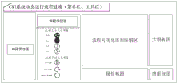
Fig. 2 is a schematic diagram of physical resource modeling in the CNI system modeling environment of fig. 1.
Fig. 3 is a schematic diagram of dynamic process modeling in the modeling environment of the CNI system of fig. 1.
Fig. 4 is a schematic diagram of modeling a dynamic operation flow of a system in the CNI system modeling environment of fig. 1.
Fig. 5 is a diagram illustrating an example of a dynamic operation flow model of the CNI system of the present invention.
Fig. 6 is a flow diagram of integrated data routing module processing in the CNI system modeling environment of fig. 1.
Fig. 7 is a schematic flow diagram of the operation of the CNI modeling system of the present invention.
Detailed Description
See fig. 1. In a preferred embodiment described below, a CNI modeling system includes at least one set of PC capable of running CNI system modeling environment software, an ethernet switch, a plurality of real physical modules, and CNI system modeling environment software formed by a physical resource modeling module, a dynamic processing modeling module, a model dynamic and static association module, a system dynamic running simulation module, and an integrated data routing module, where the CNI system modeling environment software is connected to real physical devices through ethernet, and uses UDP protocol to implement data communication with the real physical devices, the integrated data routing module implements data routing between the real physical devices and CNI system model nodes based on a hardware abstraction layer, and the real physical modules run CNI system control management software or waveform software. In the CNI system modeling environment software of a PC, a physical resource modeling module adopts a static resource model to describe physical nodes of a CNI system, connection relation physical resource model attribute information of a communication link and standardized description of the model, provides a resource model comprising a CNI system frame model, a physical module model, a calculation node model, a bus port model and a connection model, and supports physical environment static information modeling and standardized description of a CNI system real physical frame, a physical module, a chip, a port, a connection relation and CNI system resource attribute information; the dynamic processing modeling module generates a command processing action template code according to the action configuration information, and a user adds an action simulation analysis processing program for interface control document ICD information according to the CNI system design requirement to form a command processing action library; the model dynamic and static association module selects associated command processing actions from a command processing action library formed by the dynamic processing modeling module aiming at the nodes in the static physical resource model according to the action design requirements of the nodes in the CNI system, and determines the association relation of model dynamic and static processing information; the system dynamic operation simulation module provides a basic process modeling model on the basis of the physical resource modeling module and the dynamic processing modeling module, realizes the operation of the operation state and the associated action of the physical resource model, generates a configuration file according to the operation state change and the action operation process of the CNI system physical resource model set by a user, realizes the dynamic operation simulation of the CNI modeling system equipment by operating the physical resource model and driving and executing the dynamic operation simulation process by a process analysis engine, and realizes the CNI system integration test in a semi-physical environment on the basis of the data interaction between the CNI system physical model and real equipment.
The physical resource modeling module provides chip-level modeling capability and comprises four components of a physical node model of a CNI system, a communication link model of the CNI system, physical resource attribute information of the CNI system and description rules of the CNI system, wherein the physical node model of the CNI system comprises: the system comprises a rack model and a physical module model which are attached with corresponding static attribute information, a processing chip calculation node model which is divided into an ARM processor, a PPC processor, a digital signal processor DSP, a field programmable gate array FPGA and the like, a physical bus general port model which is divided into RapidIO, RS232, RS485, 1394, a controller area network CAN, an external memory interface EMIF and the like, and a unidirectional and bidirectional communication link connection general model. The static physical resource node model includes configuration information related to the basic physical attributes and the system of the nodes in the CNI system. For a generic model, the type attribute information may be further configured to clarify the type of the model. The universal bus port model comprises ports based on message or content mapping types, such as RapidIO, RS232, RS485, 1394, a controller area network CAN, an external memory interface EMIF and the like. When the CNI system dynamic processing model is modeled, the static physical resource modeling is the basis of the CNI system dynamic processing model modeling. The software modules in the CNI modeling system include: platform software, waveform software, system control management software and CNI system modeling environment software run in the real hardware module, and each software module takes interface control document ICD information interaction as a core element and realizes command control and response through ICD interaction.
The CNI system modeling environment software provides a visual interface, and an auxiliary dynamic processing modeling module generates a standardized command processing action template code and a management command processing action library. The CNI system modeling environment software generates a command processing action template code containing a specific command data entry function according to a specified command port number, and a CNI system software designer adds a response processing code aiming at a specific interface control document ICD in the template code, and the CNI system modeling environment software is mainly used for describing an action processing process of a node given by a CNI system at a software design level, namely how to respond when receiving a command. A plurality of ICD processing commands can be packaged in one command processing action template, and the command processing action template is internally distinguished through command port numbers so as to call corresponding ICD processing programs. Each command processing action template may receive data corresponding to a plurality of ports for which a template code needs to be specified when the template code is created, the template code being internally automatically registered with the attached physical model node. And finally, all command-related processing codes are brought into the command processing action library for unified management, so that the multiplexing in the system development process is facilitated, the modeling time is saved, and the command processing action codes can be conveniently changed in the joint test process so as to adapt to the change of the design requirements of the CNI system. CNI system software modeling personnel can add CNI control command ICD response processing actions related to specific models in command processing action template codes generated by CNI system modeling environment software, and can acquire and modify information of CNI system modeling environment software deployment physical nodes by calling the deployed node interfaces in the command processing action template codes to complete corresponding result packaging and sending and processing response flows, thereby realizing processing action execution.
The model dynamic and static association module establishes an association relation between a CNI system physical resource model node containing a receiving data inlet and a command processing action, each physical resource model node in the CNI system physical resource model not only comprises basic physical attributes of the nodes in the CNI system and configuration information related to the system, but also can associate the physical resource model node to the corresponding command processing action according to an interface Control document ICD (interface Control document) to which the physical resource model node needs to respond, thereby establishing a dynamic response processing function of the physical resource model node to the ICD model and increasing the dynamic command processing capability of the node. Each node can be associated with a plurality of dynamic command processing actions, and the command port values corresponding to the command processing action codes associated with the same physical resource model node are required to be different. Each physical resource model node comprises a received data inlet, and when data is received, a processing function in a corresponding command processing action code is triggered in the received data inlet to analyze and process the received data according to a port value registered by the command processing action. For each physical resource model node, through a visual interface, the associated command processing action code can be selected from a command processing action library, the association between the static physical resource model node and the command processing action is established, and the association relation between the physical resource model node and the command processing action code is stored in an XML description file of the physical resource model. After the dynamic and static association relation is established, the operation of the CNI system model can be started through a visual interface.
The system dynamic operation simulation module comprises an operation flow modeling and a flow analysis driving engine, wherein the operation flow modeling provides modeling, flow model description and analysis execution functions based on a basic flow element model and a flow step element model; when the CNI system dynamic operation flow modeling is carried out, the operation flow arrangement is carried out on the state change process and the processing action of the physical resource model node by means of the workflow technology, and the dynamic operation flow description and the flow storage are carried out by using XML. The workflow analysis driving engine executes the dynamic operation flow description file, so that serial, parallel, mixed, repeated and synchronous operation processing of node actions is realized, and normal operation of a CNI system and hardware state changes which are difficult to occur in a real environment are simulated. Different operation flow models are executed by means of workflow engine analysis driving, corresponding physical model states are called, modified and set according to flow design, simulation of a real operation scene of the system is completed, and integration testing of the CNI system in different operation states is achieved.
The integrated data routing module in the modeling environment comprises the mapping relation between the virtual node address and the real Ethernet IP address information, the address of each physical resource model node in the CNI modeling system and the IP position of real physical equipment are recorded, the connection between all model nodes in the CNI system modeling environment software and the real physical equipment is realized through the Ethernet, and the interaction between service and control data between the CNI system physical resource model and software in external real equipment is realized through a UDP protocol. All data sent to the outside by model nodes in a physical resource model of the CNI system are accessed into the integrated routing module, and the integrated data routing module judges whether to route the data to the model nodes or software in real physical equipment according to the virtual node address and the mapping relation between the virtual node address and the real physical address. The Ethernet carries the data packet which meets the format requirement of the hardware abstraction layer, and the packet head parts of all control and service data packets in the CNI modeling system contain the virtual node address, the port and the data length information. When a software program in the real equipment transmits data, an Ethernet UDP protocol is called through a hardware abstraction layer to transmit the data, and the interaction of the CNI system control data or the waveform service data between the real equipment and model nodes in the CNI system modeling environment software is driven.
The CNI system modeling environment software can realize modeling of real physical equipment, including module information, processing chip information, physical bus ports, connection relation information and node ICD message dynamic response processing, and simulation of real equipment operation flow and fault state. And establishing the incidence relation among the models layer by using an object-oriented mode in the CNI system modeling environment software, and storing the static physical resource model of the system, the dynamic and static incidence relation of the models and the dynamic operation flow by using an XML file. Visual modeling support is provided through project engineering management, a meta-model library and a graphical editing tool, and a user model is converted into a dynamic operation representation structure supported in a computer. The visual CNI system modeling environment software can realize the functions of physical resource modeling, action command processing template code generation, editing and unified management, the visual system running process modeling based on a basic process element model and a process step element model, the visual CNI system modeling and attribute configuration operation which are visual and easy to operate, and the dynamic running process simulation of the CNI system is driven by means of a workflow engine technology, so that the CNI system integration test in a semi-physical environment is supported on the basis. The static physical resource model, the dynamic command processing template and the dynamic operation flow can also form respective resource libraries for development and design personnel of different projects to reuse, and the overall modeling efficiency is improved.
See fig. 2. In the CNI system modeling environment software, a physical resource modeling perspective view mainly comprises a menu bar, a tool bar, a project management area, a resource model area, a model visualization graph editing area, an attribute view, an outline view and an eagle eye view part, wherein the resource model area provides a rack model, a physical module model, a computing node model, a bus port model and a connection model. During modeling, firstly, CNI system physical resource model items need to be established, each item corresponds to a system model in a default mode, and then the provided resource models can be directly dragged to a graphical editing area canvas to create a physical system model. After the CNI system physical platform finishes planning, the design of the module and the computing unit in the module can be finished by dragging the physical module model and designing the computing unit in the module model, which comprises an ARM processor, a PPC processor, a Digital Signal Processor (DSP) and a Field Programmable Gate Array (FPGA); the data bus transmission drive port contained on each computing unit is then programmed. And providing a general port type in a resource model of modeling environment software, and setting specific types of the port after dragging the port to a computing unit, wherein the specific types include RapidIO, RS232, RS485, 1394, a controller area network CAN, an external memory interface EMIF and the like. And then, according to system design, connecting data bus ports between different computing node models by using a connection model, wherein the connection model is in unidirectional and bidirectional connection. After the model is built, the attribute information of different units in the model can be configured in the attribute area, wherein the attribute information comprises a rack, a module, a computing node and a bus port model, and the rack attribute comprises the following steps: manufacturer, name. The module attributes include: manufacturer, name, physical address, plate number. The compute node attributes include: name, chip type, ID, physical address, manufacturer, model, electronic tag, fault status, virtual node address. Bus port attributes include: type, physical address. The modeling process must be performed in the order of system, rack, module, node, port, and connection, where the rack model can only be included in the system model, the module model can only be included in the rack model, the compute node model can only be included in the module model, and the port model can only be included in the compute node model. By means of the visual operation interface, the system model and the attribute information can be flexibly designed and adjusted. Standardized model elements can be added into the canvas in a dragging mode, and the modeling of a complex system is convenient to complete. In the CNI system modeling environment software, the models are stored according to an object-oriented method, each CNI system physical resource model is a class object which comprises a rack and a connection class object member designed during modeling, the rack class object comprises a physical module class object member designed during modeling, the physical module class object comprises a calculation node class object member designed during modeling, and the calculation node class object comprises a bus port class object member designed during modeling. Meanwhile, the CNI system modeling environment software uses XML to store the CNI system physical resource model externally.
See fig. 3. In the CNI system modeling environment software, a dynamic processing modeling perspective view mainly comprises a menu bar, a tool bar, a command processing action library management area, a code editing area and an attribute view part, and provides visual command processing action template code generation, editing and unified management functions. The command processing of each ICD in the CNI system is the inheritance of a command processing action template, corresponds to a standard Java class file, and needs to complete the realization of action processing functions specified in the class during modeling. When dynamic command modeling is carried out, firstly, a port number corresponding to a command processing action template is appointed, and then a command processing action template code is generated in a code editing area; next, the command processing code of a specific ICD is added within the command processing action template code by the CNI system software designer according to system design requirements. In the command processing action template, the node configuration information to which it is attached can be accessed and set through standard interface functions. The operation flow of the command processing action template code is as follows: firstly, completing command port registration corresponding to the ICD in a specified registration function; then the CNI system modeling environment software routes the data to the command processing action template example according to the port value; the command processing function is next called, within which the modeler-specified processing can be completed. And adding the command processing action code files completed by the modeler into a command processing action library for unified management.
And the model dynamic and static association module establishes the association relationship between the physical resource model nodes and the command processing action codes according to the modeling requirements. In the physical resource modeling perspective view of the CNI system modeling environment software, the command processing action code associated with the model node can be selected from the command processing action library through a visual operation mode. With the ClassLoader loader, only the Java code of the instance needs to be associated to the model node. When the model dynamically operates, the model node calls the Java class object processing function associated with the specified port registered in the node according to the port value after receiving the data. The association form is shown in the following example, wherein 23 ports correspond to the status detection command processing action stateCheck, and 24 ports correspond to the parameter obtaining command processing action parameter get.
<action-functions>
<function type="class">
<arg name="port">23</arg>
<arg name="class.name">
com.wisAvWorkbench.workflow.actions.stateCheck
</arg>
<arg name=“para1">1</arg>
</function>
<function type="class">
<arg name="port">24</arg>
<arg name="class.name">
com.wisAvWorkbench.workflow.actions.parameterGet
</arg>
<arg name=“para1">2</arg>
</function>
</action-functions>
According to the XML description, each node may be associated with multiple command processing action codes. When associating, each command processing action code is required to correspond to different port parameter values, otherwise, an error is reported when carrying out model checking. When the driving model runs, after each node receives data, the corresponding command processing function is called according to the port parameters to complete command processing.
See fig. 4. In the CNI system modeling environment software, a system dynamic operation process modeling perspective view mainly comprises a menu bar, a tool bar, a project management area, a process model area, a process visual graph editing area, an attribute view, an outline view and an eagle eye view part, wherein according to the operation characteristics and requirements of the CNI system, a process basic element model supported in the environment is divided into start, stop, combination and branch nodes, and a process step element model is divided into delay processing, circulation processing and general processing step nodes. The starting and stopping nodes represent the start and the end of the operation flow; a branch node refers to where a branch action sequence is triggered; the merging processing node waits for the completion of all the preorder branch tasks at the merging node according to the flow model, and then continues to execute the follow-up action after the completion of all the preorder branch tasks; the delay processing node means that the node executes delay processing action, and the delay time is a settable parameter; the loop processing refers to periodically executing an action sequence between a designated start node and an end node; the universal action node is used for adding actions specified by a user, wherein the actions refer to action processing commands of the nodes in the physical resource model of the CNI system, such as node state modification, module electronic tag acquisition and the like. In a visual modeling environment, the dynamic operation process of the CNI system can be flexibly and conveniently created by dragging, selecting, adding and deleting the process basic model. The CNI system operation flow is described through XML to form an operation flow template library, and a real physical system can be tested by combining different operation flows during testing. The driving execution of the process uses a workflow technology, and the workflow engine is used for realizing the analysis and execution of the XML file of the process model.
See fig. 5. The CNI system simulation operation process shown in fig. 5 can be established by the CNI system modeling environment software, and the start node S0 is started by the workflow engine execution process of the CNI system modeling environment software, and first, the action 1 is executed to perform the node action: modifying the SPM1 node to be in a fault state; then, executing a delay action D, and performing delay processing: delaying for 30 ms; then according to a branch processing command set by a user, executing a branch processing action S, and simultaneously triggering two branches; wherein branch 1 first performs action 2, performing a node action: the SPM2 node is powered down and then performs a delay action D, delay processing: delaying for 5ms, then executing action 3, and performing node action: the SPM2 node is powered on; branch 2 first performs action 4, performing the node action: modifying the SPM3 node to be in a fault state; then, executing a delay action D, and performing delay processing: delaying for 15ms, then executing action 5, and performing node action: the SPM4 node is powered up again; then executing the flow merging processing J, and executing a merging processing command set by a user; after the branch 1 and the branch 2 are both finished, continuing to execute the action 6, and performing a node action: and modifying the SPM1 node to be in a normal state, and finally reaching an end node S1 to finish the process simulation.
After the workflow engine starts the flow simulation operation, the operation state of the CNI system is controlled by two aspects:
(1) a command processing action code associated to a CNI system physical resource model node, the part completed by the node calling a registered command processing function when receiving data;
(2) and (3) operating a flow model, wherein the part mainly simulates the abnormal change of the state in the operation process of the system and is completed through flow modeling. After the operation simulation is started, the operation state simulation of the real CNI system is completed cooperatively by the two aspects.
When interactive test of real equipment and a virtual modeling environment is carried out, data routing and forwarding are realized based on a hardware abstraction layer technology. The virtual node address is used for marking a computing node, each computing node and real physical equipment in the system model have a virtual node address with a marked identity, and the port is used for marking a logical port used for processing data on the node. In the real equipment, CNI system control management software/waveform software calls a hardware abstraction layer interface to send data, judges whether to route the data to the current node or a model node established by CNI system modeling environment software by comparing virtual node address with local address, and uniformly delivers the data to an integrated data routing module in the CNI system modeling environment software if the data is routed to the model node. The integrated data routing module further completes data routing according to the virtual node address and the address mapping relation.
See fig. 6. In the CNI system modeling environment software, the data routing flow of the integrated data routing module is as follows: firstly, the integrated data routing module judges whether a data destination is a model node according to a virtual node address, if so, the integrated data routing module finds out a corresponding model node according to the virtual node address, calls a data receiving interface of the model node, and finds out a command processing action code to be executed in the model node according to a port number in a received data packet header; otherwise, the physical address of the real device mapped by the virtual node address is searched, and then the data is sent to the destination node through an Ethernet UDP protocol.
See fig. 7. The operation flow of the CNI modeling system based on the invention is as follows: firstly, according to the design requirements of a system, a CNI system hardware and software designer models CNI physical equipment; then according to the system design, generating a command processing action template, adding a specific action analysis code by a CNI system software designer, and forming a command processing action library; then establishing an association relation between the physical resources and the command processing action, and selecting a processing action code associated with the physical resource node from a command processing action library; then modeling the operation flow of the physical resources; then, connecting a router, a PC running CNI system modeling environment software and a real equipment module through Ethernet, configuring an integrated data routing module of the modeling environment and a routing table of the real equipment according to network information, directing a data address sent to a model node to the CNI system modeling environment software on the PC, and configuring a correct IP and a correct port; next, starting a physical model in CNI system modeling environment software as an operation state, and simultaneously starting a dynamic operation simulation flow to simulate the operation of real equipment; and finally, starting CNI system control management or waveform software in the real physical equipment, and then carrying out test and running state analysis. In the test, the CNI system control management software or waveform software runs in a real general physical device comprising an ARM processor, a PPC processor, a digital signal processor DSP and a field programmable gate array FPGA, and carries out software simulation of modeling, action and dynamic operation flow on required associated modules and processing actions through a CNI modeling system, so that system integration test in a semi-physical state is carried out. In the test, the monitoring of the running state of the system node, the observation of the data flow direction, the node attribute change and the command execution condition can be realized through the visual interface of the CNI system modeling environment software, and the working state of the system model can be controlled by setting and modifying the working parameters of the system model, so that the aim of testing the real equipment is fulfilled. The CNI system control management software and the waveform software which pass the integration test can be smoothly transplanted to a real system rack for joint test. Through multi-operation flow design and verification in a CNI system modeling environment, the system test coverage rate is improved, and the test pressure after the system is transplanted to real equipment is reduced.
Claims (10)
1. A CNI modeling system comprises at least one set of PC capable of running CNI system modeling environment software, an Ethernet switch, a plurality of real physical modules and CNI system modeling environment software consisting of a physical resource modeling module, a dynamic processing modeling module, a model dynamic and static association module, a system dynamic running simulation module and an integrated data routing module, wherein the CNI system modeling environment software is connected with real physical equipment through the Ethernet and realizes data communication with the real physical equipment by using a UDP (user datagram protocol) protocol; the integrated data routing module realizes data routing between the real physical equipment and the CNI system model node based on the hardware abstraction layer; the real physical module runs CNI system control management software or waveform software, and is characterized in that: in the CNI system modeling environment software of the PC, a physical resource modeling module adopts a static resource model to describe the physical nodes of the CNI system, the connection relation of communication links, physical resource model attribute information and the standardized description of the model; the dynamic processing modeling module generates a command processing action template code according to the action configuration information, and a user adds an action simulation analysis processing program for interface control document ICD information according to the CNI system design requirement to form a command processing action library; the model dynamic and static association module selects associated command processing actions from a command processing action library formed by the dynamic processing modeling module aiming at the nodes in the static physical resource model according to the action design requirements of the nodes in the CNI system, and determines the association relation of model dynamic and static processing information; the system dynamic operation simulation module provides a basic process modeling model on the basis of the physical resource modeling module and the dynamic processing modeling module, realizes the operation of the operation state and the associated action of the physical resource model, generates a configuration file according to the operation state change and the action operation process of the CNI system physical resource model set by a user, realizes the dynamic operation simulation of the CNI modeling system equipment by operating the physical model and driving and executing the dynamic operation simulation process by a process analysis engine, and realizes the CNI system integration test in a semi-physical environment on the basis of the data interaction between the CNI system physical model and real equipment.
2. The CNI modeling system of claim 1, wherein: the integrated data routing module realizes data routing between real physical equipment and physical resource model nodes of the CNI system based on a hardware abstraction layer; the real physical module runs CNI system control management software or waveform software.
3. The CNI modeling system of claim 1, wherein: the physical resource modeling module provides chip-level modeling and comprises four components of a physical node model of the CNI system, a communication link model of the CNI system, physical resource attribute information of the CNI system and description rules of the CNI system, wherein the physical node model, the general bus port and the general connection relation are modeled.
4. The CNI modeling system of claim 3, wherein: the CNI system physical node model comprises: the system comprises a rack model, a physical module model, a processing chip calculation node model, a physical bus general port model and a communication link connection general model, wherein the rack model and the physical module model are attached with corresponding static attribute information, the processing chip calculation node model is divided into an ARM processor, a PPC processor, a digital signal processor DSP and a field programmable gate array FPGA type, the physical bus general port model is divided into a RapidIO model, an RS232 model, an RS485 model, a 1394 model, a controller area network CAN model and an external memory interface EMIF type, and the communication link connection general model is divided into a single direction and a two-way; the attribute information of the static physical resource node model comprises the following steps: the basic physical attributes of the nodes in the CNI system are system-related configuration information.
5. The CNI modeling system of claim 1, wherein: the software modules in the CNI modeling system include: platform software, CNI system control management software and waveform software and CNI system modeling environment software run in the real hardware module, and each software module takes interface control document ICD information as a core interactive element and realizes command control and response through ICD interaction.
6. The CNI modeling system of claim 1, wherein: the CNI system modeling environment software provides a visual interface, an auxiliary dynamic processing modeling module generates a standardized command processing action template code and a management command processing action library, the generated command processing action template code comprises a command data entry function, a command port number corresponding to the command processing action template needs to be appointed when the template code is generated, a response processing code aiming at a specific interface control document ICD is added in the template code by a CNI system software designer, and the dynamic processing capability of a node responding to a received command is realized on a CNI system software design level.
7. The CNI modeling system of claim 1, wherein: the model dynamic and static association module establishes an association relation between a CNI system physical resource model node containing a data receiving inlet and command processing actions, each physical resource model node in the CNI system physical resource model comprises basic physical attributes of the node in the CNI system, system-related configuration information and interface control document ICD information needing to be responded according to the physical resource model node, and associates the physical resource model node with the corresponding command processing action so as to establish a dynamic response processing function of the node on the ICD information.
8. The CNI modeling system of claim 7, wherein: each physical resource model node comprises a data receiving inlet, and when data is received, a processing function in a corresponding command processing action code is triggered in the data receiving inlet to analyze and process the received data according to a port value registered by the command processing action; and for each physical resource model node, selecting the associated command processing action code from the command processing action library through a visual interface, establishing the association between the static physical resource model node and the command processing action, and storing the association relation between the physical resource model node and the command processing action code in an XML description file of the physical resource model.
9. The CNI modeling system of claim 1, wherein: the system dynamic operation simulation module comprises an operation process modeling and process analysis driving engine and provides modeling, process model description and analysis execution functions based on a basic process element model and a process step element model; when the CNI system dynamic operation flow modeling is carried out, the operation flow arrangement is carried out on the state change process and the processing action of the physical resource model node by means of a workflow technology, XML is used for carrying out dynamic operation flow description and flow storage, a dynamic operation flow description file is executed by a workflow analysis driving engine, the serial, parallel, mixed, repeated and synchronous operation processing of the node action is realized, and the CNI system normal operation and the hard hardware state change in a real environment are simulated; different operation flow models are executed by means of workflow engine analysis driving, corresponding physical model states are called, modified and set according to flow design, simulation of a real operation scene of the system is completed, and integration testing of the CNI system in different operation states is achieved.
10. The CNI modeling system of claim 1, wherein: the integrated data routing module comprises a mapping relation between a virtual node address and real Ethernet IP address information, and records the address of each physical resource model node in the CNI modeling system and the IP position of real physical equipment, realizes the connection between all the physical resource model nodes in the CNI system modeling environment software and the real physical equipment through the Ethernet, and realizes the interaction between service and control data between the CNI system physical resource model nodes and software in external real equipment through a UDP protocol; all model nodes in a physical resource model of the CNI system send data to the outside to access the integrated routing module, the integrated data routing module judges whether a data destination is a model node according to a virtual node address, if so, the integrated data routing module finds a corresponding model node according to the virtual node address, calls a data receiving interface of the model node, and finds a command processing action code to be executed in the model node according to a port number in a received data packet header; otherwise, the physical address of the real device mapped by the virtual node address is searched, and then the data is sent to the destination node through an Ethernet UDP protocol.
Priority Applications (1)
| Application Number | Priority Date | Filing Date | Title |
|---|---|---|---|
| CN201810143426.0A CN108460199B (en) | 2018-02-11 | 2018-02-11 | CNI modeling system |
Applications Claiming Priority (1)
| Application Number | Priority Date | Filing Date | Title |
|---|---|---|---|
| CN201810143426.0A CN108460199B (en) | 2018-02-11 | 2018-02-11 | CNI modeling system |
Publications (2)
| Publication Number | Publication Date |
|---|---|
| CN108460199A CN108460199A (en) | 2018-08-28 |
| CN108460199B true CN108460199B (en) | 2021-10-15 |
Family
ID=63216405
Family Applications (1)
| Application Number | Title | Priority Date | Filing Date |
|---|---|---|---|
| CN201810143426.0A Active CN108460199B (en) | 2018-02-11 | 2018-02-11 | CNI modeling system |
Country Status (1)
| Country | Link |
|---|---|
| CN (1) | CN108460199B (en) |
Families Citing this family (7)
| Publication number | Priority date | Publication date | Assignee | Title |
|---|---|---|---|---|
| CN109639774B (en) * | 2018-11-26 | 2021-02-05 | 西南电子技术研究所(中国电子科技集团公司第十研究所) | Dynamic change environment self-adaptive service interaction system |
| CN109947402B (en) * | 2019-03-27 | 2022-11-11 | 深兰科技(上海)有限公司 | Project development system |
| CN111274750B (en) * | 2020-03-05 | 2023-05-30 | 中国工程物理研究院计算机应用研究所 | FPGA simulation verification system and method based on visual modeling |
| CN113541823B (en) * | 2020-03-30 | 2023-04-14 | 西南电子技术研究所(中国电子科技集团公司第十研究所) | General hardware processing platform of CNI comprehensive detector |
| CN112260776B (en) * | 2020-10-12 | 2023-05-09 | 西南电子技术研究所(中国电子科技集团公司第十研究所) | Comprehensive combined test system for ground surface communication detection of airborne CNI performance |
| CN113064737B (en) * | 2021-03-26 | 2023-03-31 | 中国航空无线电电子研究所 | Method for enabling components of software communication architecture to run in parallel on multi-core processor |
| WO2023004805A1 (en) * | 2021-07-30 | 2023-02-02 | 西门子股份公司 | Workflow modeling implementation system and method, and storage medium |
Family Cites Families (8)
| Publication number | Priority date | Publication date | Assignee | Title |
|---|---|---|---|---|
| US5640694A (en) * | 1995-05-03 | 1997-06-17 | Northrop Grumman Corporation | Integrated RF system with segmented frequency conversion |
| US6675289B1 (en) * | 2000-06-30 | 2004-01-06 | Broadcom Corporation | System and method for executing hybridized code on a dynamically configurable hardware environment |
| US20110113082A1 (en) * | 2007-02-07 | 2011-05-12 | Amirhossein Alimohammad | Signal filtering and filter design techniques |
| CN102006658B (en) * | 2010-12-07 | 2013-04-17 | 中国人民解放军理工大学 | Chain game based synergetic transmission method in wireless sensor network |
| CN105390039B (en) * | 2015-10-12 | 2018-11-27 | 四川天中星航空科技有限公司 | The outfield CNI simulation system |
| CN105701605B (en) * | 2016-01-08 | 2019-11-01 | 中国航空无线电电子研究所 | A kind of waveform library management equipment applied in integrated communication Navigation Identification System |
| CN105844020A (en) * | 2016-03-23 | 2016-08-10 | 中国电子科技集团公司第十研究所 | Abstract integration design method of complex electronic system |
| CN106020936A (en) * | 2016-06-07 | 2016-10-12 | 深圳证券通信有限公司 | Virtual machine dispatching method and device for financial cloud platform on basis of operating loads |
-
2018
- 2018-02-11 CN CN201810143426.0A patent/CN108460199B/en active Active
Also Published As
| Publication number | Publication date |
|---|---|
| CN108460199A (en) | 2018-08-28 |
Similar Documents
| Publication | Publication Date | Title |
|---|---|---|
| CN108460199B (en) | CNI modeling system | |
| US20250377866A1 (en) | Software defined network controller | |
| CN107220064B (en) | An interface configuration development method of numerical control system | |
| CN111859834B (en) | A UVM-based verification platform development method, system, terminal and storage medium | |
| CN114036013B (en) | Multi-module synchronous verification platform and verification method for transponder chip based on UVM | |
| CN109739699A (en) | A SPI Verification Method Based on UVM Verification Methodology | |
| JP2008170998A (en) | System and method for turbine control simulation | |
| CN110071822B (en) | Testing device and testing method for 5G core network infrastructure | |
| CN106599398B (en) | Simulation method and device for integrated management system of space and earth | |
| JPH10232890A (en) | Embedded logic analyzer for programmable logic circuits | |
| CN116090376B (en) | Chip integrated verification component development method, device and computer equipment | |
| CN110048904A (en) | A kind of test macro and method for user-plane function network element in 5G core net | |
| CN102916848A (en) | Automatic test method of Ethernet interface equipment based on script technology | |
| CN114757135A (en) | Programmable logic device verification method and system based on demand-driven verification | |
| CN113467886A (en) | Pressure measurement engine cluster construction method based on containerized scheduling | |
| CN117852172A (en) | Real-time control system for ground closed-loop system | |
| CN103812905B (en) | An integrated generation system and method for Internet of Things terminal applications | |
| CN120492248A (en) | Method, device, equipment and medium for generating and testing register model and register transmission level | |
| CN118054933A (en) | UVM-based horizontal multiplexing platform and construction method thereof | |
| Hill et al. | Model-driven engineering for development-time QoS validation of component-based software systems | |
| EP4462299A1 (en) | Dynamic workflow implementation method and system, medium, and program product | |
| CN117787154A (en) | Simulation verification method, electronic device, and computer-readable medium | |
| CN117807924A (en) | Software framework and method for software and hardware co-simulation and business verification of network chip design | |
| CN114189534A (en) | A Design Method of Device Interaction Software Simulation Program in Internet of Things System | |
| CN111274750A (en) | FPGA simulation verification system and method based on visual modeling |
Legal Events
| Date | Code | Title | Description |
|---|---|---|---|
| PB01 | Publication | ||
| PB01 | Publication | ||
| SE01 | Entry into force of request for substantive examination | ||
| SE01 | Entry into force of request for substantive examination | ||
| GR01 | Patent grant | ||
| GR01 | Patent grant |