CN103630108A - Three-dimensional small-angle measuring device and method utilizing three-dimensional small-angle measuring device to dynamically measure three-dimensional angle variation - Google Patents
Three-dimensional small-angle measuring device and method utilizing three-dimensional small-angle measuring device to dynamically measure three-dimensional angle variation Download PDFInfo
- Publication number
- CN103630108A CN103630108A CN201310649534.2A CN201310649534A CN103630108A CN 103630108 A CN103630108 A CN 103630108A CN 201310649534 A CN201310649534 A CN 201310649534A CN 103630108 A CN103630108 A CN 103630108A
- Authority
- CN
- China
- Prior art keywords
- coordinate system
- dimensional
- measuring device
- cross
- angle
- Prior art date
- Legal status (The legal status is an assumption and is not a legal conclusion. Google has not performed a legal analysis and makes no representation as to the accuracy of the status listed.)
- Granted
Links
Images


Classifications
-
- G—PHYSICS
- G01—MEASURING; TESTING
- G01B—MEASURING LENGTH, THICKNESS OR SIMILAR LINEAR DIMENSIONS; MEASURING ANGLES; MEASURING AREAS; MEASURING IRREGULARITIES OF SURFACES OR CONTOURS
- G01B11/00—Measuring arrangements characterised by the use of optical techniques
- G01B11/26—Measuring arrangements characterised by the use of optical techniques for measuring angles or tapers; for testing the alignment of axes
-
- G—PHYSICS
- G01—MEASURING; TESTING
- G01C—MEASURING DISTANCES, LEVELS OR BEARINGS; SURVEYING; NAVIGATION; GYROSCOPIC INSTRUMENTS; PHOTOGRAMMETRY OR VIDEOGRAMMETRY
- G01C1/00—Measuring angles
Landscapes
- Physics & Mathematics (AREA)
- General Physics & Mathematics (AREA)
- Engineering & Computer Science (AREA)
- Radar, Positioning & Navigation (AREA)
- Remote Sensing (AREA)
- Length Measuring Devices By Optical Means (AREA)
Abstract
Description
技术领域 technical field
本发明属于光学精密测量领域,尤其涉及一种三维角度测量装置及其用于精确测量三维小角度变化量的方法。 The invention belongs to the field of optical precision measurement, and in particular relates to a three-dimensional angle measuring device and a method for accurately measuring three-dimensional small angle variation.
背景技术 Background technique
角度测量是工业生产、质量控制等环节中至关重要的一步,通常可以分为静态测量和动态测量两种。静态测量是指对加工或装配成的零组件角度以及仪器转动后恢复至静态等条件下的角位置的测量。动态角度测量是指对物体或系统在运动过程中,即设备在一定角速度和角加速度运动条件下的实时角度信号的测量,如卫星轨道对地球赤道面的夹角、精密设备主轴转动时的轴线角漂移。 Angle measurement is a crucial step in industrial production, quality control, etc. It can usually be divided into static measurement and dynamic measurement. Static measurement refers to the measurement of the angle of the processed or assembled components and the angular position of the instrument under the conditions of returning to static state after rotation. Dynamic angle measurement refers to the measurement of the real-time angle signal of the object or system during the motion process, that is, the equipment under the condition of certain angular velocity and angular acceleration, such as the angle between the satellite orbit and the earth's equatorial plane, the axis of the precision equipment when the main shaft rotates corner drift.
小角度测量一般指10o以下甚至几十角秒的角度测量,其特点是测量范围小、测量精度高,测量误差一般为1″~2″,甚至可达0.1″或更小。光学测量方法具有测量准确度高和非接触测量以及灵敏度高等特点,被广泛应用于小角度的测量,在某些场合下正在逐渐取代传统的机械式和电磁式测量方法。目前,常用的光学测角方法主要有光学分度头法、多面棱体法、光电编码法、自准直法、平行干涉图法、圆光栅法、光学内反射法、激光干涉法以及环形激光法等。其中,光学准直法(包括自准直法)是一种应用相对较多的高精度小角度的测量方法。其优点是,原理简单,应用较为方便,测量精度和测量灵敏度高。但是,上述的测角方法通常只适用于一维或二维角度测量,不能实现对滚转角的测量。 Small angle measurement generally refers to angle measurement below 10o or even tens of arc seconds. It is characterized by small measurement range and high measurement accuracy. The measurement error is generally 1″~2″, or even 0.1″or smaller. Optical measurement methods have With the characteristics of high measurement accuracy, non-contact measurement and high sensitivity, it is widely used in the measurement of small angles, and is gradually replacing traditional mechanical and electromagnetic measurement methods in some occasions. At present, the commonly used optical angle measurement methods are mainly Optical dividing head method, polyhedral prism method, photoelectric encoding method, self-collimation method, parallel interferogram method, circular grating method, optical internal reflection method, laser interference method and ring laser method, etc. Among them, the optical collimation method ( Including the autocollimation method) is a relatively high-precision small-angle measurement method. Its advantages are that the principle is simple, the application is more convenient, and the measurement accuracy and measurement sensitivity are high. However, the above-mentioned angle measurement method is usually only applicable In one-dimensional or two-dimensional angle measurement, the measurement of roll angle cannot be realized.
发明内容 Contents of the invention
本发明的目的在于提供一种非接触式的三维小角度测量装置及其用于精确测量三维小角度变化量的方法,以实现待测点与基准之间三维小角度变化量的高精度(角秒级)动态测量。 The object of the present invention is to provide a non-contact three-dimensional small-angle measuring device and its method for accurately measuring three-dimensional small-angle variation, so as to achieve high precision (angle seconds) dynamic measurement.
本发明的三维小角度测量装置,包括发射/接收装置、反射装置和数据处理计算机。发射/接收装置包括LED光源、十字型通光孔、分光棱镜A、测量镜头和光电探测器。LED光源发出的光,通过十字型通光、分光棱镜A后,再经测量镜头准直后入射至反射装置的反射面,然后反射回测量镜头,最后经分光棱镜A入射到光电探测器;数据处理计算机与光电探测器连通,实时采集图像数据并解算反射装置相对于发射/接收装置的三维角度变化量。 The three-dimensional small-angle measuring device of the present invention includes a transmitting/receiving device, a reflecting device and a data processing computer. The transmitting/receiving device includes an LED light source, a cross-shaped aperture, a spectroscopic prism A, a measuring lens and a photodetector. The light emitted by the LED light source passes through the cross-shaped light-passing and beam-splitting prism A, then is collimated by the measuring lens, and then enters the reflective surface of the reflection device, then reflects back to the measuring lens, and finally enters the photodetector through the beam-splitting prism A; the data The processing computer communicates with the photoelectric detector, collects image data in real time and calculates the three-dimensional angle variation of the reflecting device relative to the transmitting/receiving device.
所述的L ED光源中心波长为632.8nm; The central wavelength of the LED light source is 632.8nm;
所述的十字型通光孔位于测量镜头与分光棱镜A组合而成的光具组的焦点位置; The cross-shaped aperture is located at the focal position of the optical train composed of the measuring lens and the beam splitting prism A;
所述的分光棱镜A边长为20mm,玻璃材料为BK7,与测量镜头同轴安装,与测量镜头最后一个光学面相距35.5mm; The side length of the beam splitting prism A is 20mm, the glass material is BK7, installed coaxially with the measuring lens, and the distance from the last optical surface of the measuring lens is 35.5mm;
所述的测量镜头包含6个普通球面镜透镜,所述6个球面镜透镜的球面形状、厚度、材料参数为: Described measuring lens comprises 6 common spherical mirror lenses, and the spherical shape, thickness, material parameter of described 6 spherical mirror lenses are:
曲面1:曲率半径167.731mm,厚度20.468mm,口径100mm,玻璃折射率1.43,玻璃阿贝系数95.0; Surface 1: radius of curvature 167.731mm, thickness 20.468mm, aperture 100mm, glass refractive index 1.43, glass Abbe coefficient 95.0;
曲面2:曲率半径-286.907mm,口径100mm; Surface 2: radius of curvature -286.907mm, caliber 100mm;
间隔1:17.482mm; Interval 1: 17.482mm;
曲面3:曲率半径-247.520mm,厚度8.344mm,口径100mm,玻璃折射率1.80,玻璃阿贝系数42.4; Surface 3: radius of curvature -247.520mm, thickness 8.344mm, aperture 100mm, glass refractive index 1.80, glass Abbe coefficient 42.4;
曲面4:曲率半径1255.162mm,口径100mm; Surface 4: radius of curvature 1255.162mm, caliber 100mm;
间隔2:11.083mm Interval 2: 11.083mm
曲面5:曲率半径137.666mm,厚度13.163mm,口径85mm,玻璃折射率1.49,玻璃阿贝系数70.4; Surface 5: radius of curvature 137.666mm, thickness 13.163mm, aperture 85mm, glass refractive index 1.49, glass Abbe coefficient 70.4;
曲面6:曲率半径1571.168mm,口径85mm; Surface 6: radius of curvature 1571.168mm, caliber 85mm;
间隔3:144.138mm; Interval 3: 144.138mm;
曲面7:曲率半径-94.840mm,厚度4.504mm,口径40mm,玻璃折射率1.52,玻璃阿贝系数64.1; Surface 7: radius of curvature -94.840mm, thickness 4.504mm, aperture 40mm, glass refractive index 1.52, glass Abbe number 64.1;
曲面8:曲率半径-135.891mm,口径40mm; Surface 8: radius of curvature -135.891mm, caliber 40mm;
间隔4:48.151mm; Interval 4: 48.151mm;
曲面9:曲率半径-69.725,厚度4.914mm,口径40mm,玻璃折射率1.71,玻璃阿贝系数53.8; Surface 9: radius of curvature -69.725, thickness 4.914mm, aperture 40mm, glass refractive index 1.71, glass Abbe coefficient 53.8;
曲面10:曲率半径126.670,口径40mm; Surface 10: radius of curvature 126.670, caliber 40mm;
间隔5:3.589mm Interval 5: 3.589mm
曲面11:曲率半径109.210,厚度18.861mm,口径40mm,玻璃折射率1.59,玻璃阿贝系数35.5; Curved surface 11: radius of curvature 109.210, thickness 18.861mm, aperture 40mm, glass refractive index 1.59, glass Abbe coefficient 35.5;
曲面12:曲率半径-123.015,口径40mm; Surface 12: radius of curvature -123.015, caliber 40mm;
所述的光电探测器的光敏面位于测量镜头与分光棱镜A组合而成的光具组的离焦面上,所述的离焦面在不同视场位置的弥散斑90%能量集中于5×5探测器像元的内,且不同视场位置点列图均方根半径值的差值小于1μm; The photosensitive surface of the photodetector is located on the defocused plane of the optical train composed of the measuring lens and the dichroic prism A, and 90% of the energy of the defocused spot at different positions of the field of view on the defocused plane is concentrated at 5× Within 5 detector pixels, and the difference between the root mean square radius values of the spot diagrams of different field of view positions is less than 1 μm;
所述反射装置,包括四个平面反射镜和一个分光棱镜B,四个平面反射镜两个为一组,组成夹角为180°-2φ的组合反射镜A和组合反射镜B,分布于分光棱镜B的相邻两则;发射/接收装置发出的平行光经分光棱镜B后分成两束,分别入射至组合反射镜A和组合反射镜B,反射光再次经分光棱镜B后返回,返回发射/接收装置。 The reflection device includes four plane reflectors and a dichroic prism B, two of the four plane reflectors form a group, forming a combined reflector A and a combined reflector B with an included angle of 180°-2 φ , distributed in There are two adjacent beam-splitting prisms; the parallel light emitted by the transmitting/receiving device is divided into two beams after passing through the beam-splitting prism B, and they are respectively incident on the combined reflector A and combined reflector B, and the reflected light returns after passing through the beam-splitting prism B again. Transmitter/receiver device.
用本发明的装置动态测量三维小角度变化量的方法,其特征在于,包括以下步骤: The method for dynamically measuring three-dimensional small angle variation with the device of the present invention is characterized in that it comprises the following steps:
(1)建立坐标系: (1) Establish a coordinate system:
建立基准坐标系F、光电探测器成像面坐标系 
成像面坐标系


基准坐标系F记为XYZ,Z轴为此时的测量镜头光轴方向,Y轴垂直于探测器成像面背向分光棱镜A,X轴由左手定规确定; The reference coordinate system F is marked as XYZ, the Z axis is the optical axis direction of the measurement lens at this time, the Y axis is perpendicular to the imaging surface of the detector and faces away from the beam splitter prism A, and the X axis is determined by the left-hand rule;
组合反射镜A对应的坐标系FA记为XaYaZa,Ya轴沿组合反射镜A两平面反射镜的交线,Za轴背向分光棱镜B, YaZa平面平分两平面反射镜的夹角,且Xa轴由左手定规确定,因此,组合反射镜A的两个反射面


类似FA,建立组合反射镜B对应的坐标系FB,并记为XbYbZb,则组合反射镜B的两个反射面


(2)标定坐标系FA与坐标系FB的关系: (2) Calibrate the relationship between the coordinate system FA and the coordinate system FB:
2.1 图像采集 2.1 Image acquisition
静态条件下,采集经反射装置反射回的十字光斑图像k 0幅,k 0取值为10~100; Under static conditions, collect k 0 images of the cross spot reflected by the reflection device, and the value of k 0 is 10 to 100;
2.2 十字光斑定位 2.2 Cross spot positioning
根据文献《根据边缘梯度方向的十字丝目标快速自动检测》(2004年发表于《光学技术》第30卷第3期)提出的十字丝目标快速识别算法,提取十字光斑在光电探测器成像面坐标系中的位置;并将k 0幅图像十字光斑的位置的均值作为最终十字光斑位置,记为


2.3 计算坐标系FA在坐标系F中的姿态矩阵
入射方向向量为


式(1)中,


在坐标系F中,


式(3)中, 表示测量镜头主点坐标;
将式(2)和式(3)代入式(1),得出反射面

取


式(5)中,


2.4 计算坐标系FB在坐标系F中的姿态矩阵
步骤2.3可知,取


根据式(6),利用Q-法确定姿态矩阵
2.5 计算坐标系FB在坐标系FA中的姿态矩阵

(3)动态测量三维角度变化量: (3) Dynamic measurement of three-dimensional angle variation:
3.1 动态条件下,实时采集经反射装置反射回的十字光斑图像; 3.1 Under dynamic conditions, real-time acquisition of the cross spot image reflected by the reflection device;
3.2 十字光斑定位,方法如步骤2.2所述; 3.2 Cross spot positioning, the method is as described in step 2.2;
3.3 计算反射装置姿态相对变化量,方法如下: 3.3 Calculate the relative change in attitude of the reflector, the method is as follows:
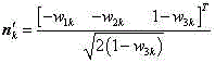
取
![]()

![]()

根据式(8),利用Q-法确定![]()

![]()


![]()
![]()
3.4 计算反射装置三维角度变化量 3.4 Calculate the three-dimensional angle change of the reflector
根据姿态相对变化量
本发明的优点:本发明提出的组合反射镜自准直系统的测量原理与传统的自准直系统的主要区别是它能分辨滚动角的微小变动量,在原理上实现了对空间三维小角度的测量;准直光发射和接收共用一个测量镜头,光学结构相对简单紧凑,有利于系统的小型化;利用多矢量姿态估计的算法计算姿态矩阵,获得三维角度的实时变化量,具有计算量小精度高的特点;此外,在测量之初标定和组合发射镜的安装关系,也有利于提高系统测量精度。 Advantages of the present invention: The main difference between the measurement principle of the self-collimation system of combined mirrors proposed by the present invention and the traditional self-collimation system is that it can distinguish the small variation of the rolling angle, and realizes the measurement of three-dimensional small angles in space in principle. measurement; the collimated light emission and reception share a measurement lens, the optical structure is relatively simple and compact, which is conducive to the miniaturization of the system; the multi-vector attitude estimation algorithm is used to calculate the attitude matrix, and the real-time change of the three-dimensional angle is obtained, which has a small amount of calculation The characteristics of high precision; in addition, at the beginning of the measurement, the calibration and the installation relationship of the combined reflector are also conducive to improving the measurement accuracy of the system.
附图说明 Description of drawings
图1是三维小角度测量装置结构示意图, Fig. 1 is a structural schematic diagram of a three-dimensional small-angle measuring device,
图2是发射/接收装置测量镜头结构示意图。 Fig. 2 is a schematic structural diagram of the measuring lens of the transmitting/receiving device.
具体实施方式 Detailed ways
实施例: Example:
本发明的三维小角度测量装置,包括发射/接收装置1、反射装置2和数据处理计算机11,其中,发射/接收装置和反射装置分别固联安装于测量基准与待测点。发射/接收装置包括LED光源3、十字型通光孔4、分光棱镜A 5、测量镜头6和光电探测器7。LED光源3发出的光,通过十字型通光孔4、分光棱镜A 5后,再经测量镜头6准直后入射至反射装置2的反射面,然后反射回测量镜头6,最后经分光棱镜A 5入射到光电探测器7;数据处理计算机11与光电探测器7连接,实时采集图像数据并解算反射装置2相对发射/接收装置1的三维角度变化量。
The three-dimensional small-angle measuring device of the present invention includes a transmitting/receiving device 1, a reflecting device 2 and a data processing computer 11, wherein the transmitting/receiving device and the reflecting device are respectively fixedly connected to the measurement reference and the point to be measured. The transmitting/receiving device includes an LED light source 3, a cross-shaped light hole 4, a beam splitting prism A 5, a measuring lens 6 and a
所述的L ED光源3中心波长为632.8nm; The central wavelength of the LED light source 3 is 632.8nm;
所述的十字型通光孔4位于测量镜头6与分光棱镜A 5组合而成的光具组的焦点位置; Described cross-shaped aperture 4 is positioned at the focal position of the optical train that measuring lens 6 and spectroscopic prism A 5 are combined;
所述的分光棱镜A 5边长为20mm,玻璃材料为BK7,与测量镜头6同轴安装,与测量镜头6最后一个光学面相距35.5mm; The side length of described beam splitting prism A 5 is 20mm, and the glass material is BK7, which is coaxially installed with measuring lens 6, and is 35.5mm apart from the last optical surface of measuring lens 6;
所述的测量镜头6包含6个普通球面镜透镜,所述透镜的球面形状、厚度、材料参数为: Described measuring lens 6 comprises 6 common spherical mirror lenses, and the spherical shape of described lens, thickness, material parameter are:
曲面S1:曲率半径167.731mm,厚度20.468mm,口径100mm,玻璃折射率1.43,玻璃阿贝系数95.0; Surface S1: radius of curvature 167.731mm, thickness 20.468mm, aperture 100mm, glass refractive index 1.43, glass Abbe coefficient 95.0;
曲面S2:曲率半径-286.907mm,口径100mm; Surface S2: radius of curvature -286.907mm, caliber 100mm;
间隔d1:17.482mm; Interval d1: 17.482mm;
曲面S3:曲率半径-247.520mm,厚度8.344mm,口径100mm,玻璃折射率1.80,玻璃阿贝系数42.4; Surface S3: radius of curvature -247.520mm, thickness 8.344mm, aperture 100mm, glass refractive index 1.80, glass Abbe coefficient 42.4;
曲面S4:曲率半径1255.162mm,口径100mm; Surface S4: radius of curvature 1255.162mm, caliber 100mm;
间隔d2:11.083mm Interval d2: 11.083mm
曲面S5:曲率半径137.666mm,厚度13.163mm,口径85mm,玻璃折射率1.49,玻璃阿贝系数70.4; Surface S5: radius of curvature 137.666mm, thickness 13.163mm, aperture 85mm, glass refractive index 1.49, glass Abbe coefficient 70.4;
曲面S6:曲率半径1571.168mm,口径85mm; Surface S6: radius of curvature 1571.168mm, caliber 85mm;
间隔d3:144.138mm; Interval d3: 144.138mm;
曲面S7:曲率半径-94.840mm,厚度4.504mm,口径40mm,玻璃折射率1.52,玻璃阿贝系数64.1; Surface S7: radius of curvature -94.840mm, thickness 4.504mm, aperture 40mm, glass refractive index 1.52, glass Abbe number 64.1;
曲面S8:曲率半径-135.891mm,口径40mm; Surface S8: radius of curvature -135.891mm, caliber 40mm;
间隔d4:48.151mm; Interval d4: 48.151mm;
曲面S9:曲率半径-69.725,厚度4.914mm,口径40mm,玻璃折射率1.71,玻璃阿贝系数53.8; Surface S9: radius of curvature -69.725, thickness 4.914mm, aperture 40mm, glass refractive index 1.71, glass Abbe coefficient 53.8;
曲面S10:曲率半径126.670,口径40mm; Surface S10: radius of curvature 126.670, caliber 40mm;
间隔d5:3.589mm Interval d5: 3.589mm
曲面S11:曲率半径109.210,厚度18.861mm,口径40mm,玻璃折射率1.59,玻璃阿贝系数35.5; Surface S11: radius of curvature 109.210, thickness 18.861mm, aperture 40mm, glass refractive index 1.59, glass Abbe coefficient 35.5;
曲面S12:曲率半径-123.015,口径40mm Surface S12: radius of curvature -123.015, diameter 40mm
所述的光电探测器7的像元数为1024×1024,像元尺寸5.45μm×5.45μm;光电探测器7的光敏面位于测量镜头6与分光棱镜A 5组合而成的光具组的离焦面上,所述的离焦面在不同视场位置的弥散斑90%能量集中于5×5探测器像元的内,且不同视场位置点列图均方根半径值的差值小于1μm;
The pixel number of described
所述反射装置2,包括四个平面反射镜和一个分光棱镜B 8,四个平面反射镜两个为一组组成夹角为179.9°的组合反射镜A9和组合反射镜B10,分布于分光棱镜B8的相邻两则;发射/接收装置发出的平行光经分光棱镜B8后分成两束,分别入射至组合反射镜A9和B10,反射光再次经分光棱镜B8后返回,返回发射/接收装置1。 Described reflector 2 comprises four plane reflectors and a dichroic prism B8, two of four plane reflectors are a group of composite reflector A9 and composite reflector B10 that form an included angle of 179.9 °, are distributed in dichroic prism The two adjacent to B8; the parallel light emitted by the transmitting/receiving device is divided into two beams after passing through the beam splitting prism B8, which are respectively incident on the combined mirrors A9 and B10, and the reflected light returns through the beam splitting prism B8 again and returns to the transmitting/receiving device 1 .
用本发明的装置动态测量三维小角度变化量的方法,其特征在于,包括以下步骤: The method for dynamically measuring three-dimensional small angle variation with the device of the present invention is characterized in that it comprises the following steps:
(1)建立坐标系: (1) Establish a coordinate system:
(2)标定坐标系FA与坐标系FB的关系: (2) Calibrate the relationship between the coordinate system FA and the coordinate system FB:
2.1 静态条件下,采集经反射装置反射回的十字光斑图像50幅; 2.1 Under static conditions, collect 50 cross spot images reflected by the reflection device;
2.2 十字光斑定位 2.2 Cross spot positioning
2.3 计算坐标系FA在坐标系F中的姿态矩阵
2.4 计算坐标系FB在坐标系F中的姿态矩阵
2.5 计算坐标系FB在坐标系FA中的姿态矩阵
(3)动态测量三维角度变化量: (3) Dynamic measurement of three-dimensional angle variation:
3.1 动态条件下,实时采集经反射装置反射回的十字光斑图像; 3.1 Under dynamic conditions, real-time acquisition of the cross spot image reflected by the reflection device;
3.2 十字光斑定位 3.2 Cross spot positioning
3.3 计算发射装置姿态相对变化量 3.3 Calculation of the relative change in attitude of the launching device
3.4 计算发射装置三维角度变化量。 3.4 Calculate the three-dimensional angle change of the launch device.
Claims (7)


Priority Applications (1)
| Application Number | Priority Date | Filing Date | Title |
|---|---|---|---|
| CN201310649534.2A CN103630108B (en) | 2013-12-06 | 2013-12-06 | A kind of three-dimensional small-angle and the method for dynamic measurement three-dimensional perspective variable quantity thereof |
Applications Claiming Priority (1)
| Application Number | Priority Date | Filing Date | Title |
|---|---|---|---|
| CN201310649534.2A CN103630108B (en) | 2013-12-06 | 2013-12-06 | A kind of three-dimensional small-angle and the method for dynamic measurement three-dimensional perspective variable quantity thereof |
Publications (2)
| Publication Number | Publication Date |
|---|---|
| CN103630108A true CN103630108A (en) | 2014-03-12 |
| CN103630108B CN103630108B (en) | 2016-06-01 |
Family
ID=50211399
Family Applications (1)
| Application Number | Title | Priority Date | Filing Date |
|---|---|---|---|
| CN201310649534.2A Active CN103630108B (en) | 2013-12-06 | 2013-12-06 | A kind of three-dimensional small-angle and the method for dynamic measurement three-dimensional perspective variable quantity thereof |
Country Status (1)
| Country | Link |
|---|---|
| CN (1) | CN103630108B (en) |
Cited By (11)
| Publication number | Priority date | Publication date | Assignee | Title |
|---|---|---|---|---|
| CN104880200A (en) * | 2014-05-13 | 2015-09-02 | 北京航天计量测试技术研究所 | Composite guidance system initial attitude on-site calibration system and method |
| CN108398104A (en) * | 2018-02-01 | 2018-08-14 | 中国科学院国家天文台南京天文光学技术研究所 | The photoelectricity dynamic angle measuring devices and its method of random error can be reduced |
| CN108458692A (en) * | 2018-02-02 | 2018-08-28 | 中国科学院西安光学精密机械研究所 | Close-range three-dimensional attitude measurement device and measurement method |
| CN109341600A (en) * | 2018-09-18 | 2019-02-15 | 重庆邮电大学 | A three-axis photoelectric autocollimator |
| CN109556566A (en) * | 2018-12-06 | 2019-04-02 | 中国科学院长春光学精密机械与物理研究所 | Relative dimensional attitude angle system and method between three pedestals of one kind |
| CN109579782A (en) * | 2019-01-11 | 2019-04-05 | 哈尔滨工业大学 | A kind of big working distance auto-collimation three-dimensional perspective measuring device of high-precision and method |
| CN109579781A (en) * | 2019-01-11 | 2019-04-05 | 哈尔滨工业大学 | A kind of big working distance auto-collimation three-dimensional measurement of absolute angle apparatus and method of high-precision |
| CN109631827A (en) * | 2019-01-11 | 2019-04-16 | 哈尔滨工业大学 | The anti-interference big working distance autocollimation of double light sources high-precision and method based on measurement of absolute angle |
| CN109708559A (en) * | 2018-12-20 | 2019-05-03 | 重庆邮电大学 | A method of measuring angle of photoelectric autocollimator based on corner mirror |
| CN112083578A (en) * | 2020-08-26 | 2020-12-15 | 中国科学院西安光学精密机械研究所 | Target simulator for image surface docking of photoelectric equipment, debugging system and method |
| CN114509026A (en) * | 2022-04-19 | 2022-05-17 | 中国科学院西安光学精密机械研究所 | Sub-arcsecond angle measurement system, method and relative deformation angle measurement method |
Citations (4)
| Publication number | Priority date | Publication date | Assignee | Title |
|---|---|---|---|---|
| JP2008249349A (en) * | 2007-03-29 | 2008-10-16 | Fujinon Corp | Posture change measuring method and apparatus |
| CN101598540A (en) * | 2009-06-24 | 2009-12-09 | 广东威创视讯科技股份有限公司 | 3-D positioning method and 3 D positioning system |
| CN101691998A (en) * | 2009-10-16 | 2010-04-07 | 中国科学院上海光学精密机械研究所 | Two-dimensional laser autocollimator |
| CN102176086A (en) * | 2011-01-19 | 2011-09-07 | 哈尔滨工业大学 | Two-dimensional photoelectric auto-collimation method and device of polarized light plane mirror reference common-path compensation |
-
2013
- 2013-12-06 CN CN201310649534.2A patent/CN103630108B/en active Active
Patent Citations (4)
| Publication number | Priority date | Publication date | Assignee | Title |
|---|---|---|---|---|
| JP2008249349A (en) * | 2007-03-29 | 2008-10-16 | Fujinon Corp | Posture change measuring method and apparatus |
| CN101598540A (en) * | 2009-06-24 | 2009-12-09 | 广东威创视讯科技股份有限公司 | 3-D positioning method and 3 D positioning system |
| CN101691998A (en) * | 2009-10-16 | 2010-04-07 | 中国科学院上海光学精密机械研究所 | Two-dimensional laser autocollimator |
| CN102176086A (en) * | 2011-01-19 | 2011-09-07 | 哈尔滨工业大学 | Two-dimensional photoelectric auto-collimation method and device of polarized light plane mirror reference common-path compensation |
Non-Patent Citations (1)
| Title |
|---|
| 张之江 等: "三维小角度测量系统建模", 《计量学报》 * |
Cited By (15)
| Publication number | Priority date | Publication date | Assignee | Title |
|---|---|---|---|---|
| CN104880200A (en) * | 2014-05-13 | 2015-09-02 | 北京航天计量测试技术研究所 | Composite guidance system initial attitude on-site calibration system and method |
| CN104880200B (en) * | 2014-05-13 | 2017-12-22 | 北京航天计量测试技术研究所 | Combined guidance system initial attitude field calibration system and method |
| CN108398104A (en) * | 2018-02-01 | 2018-08-14 | 中国科学院国家天文台南京天文光学技术研究所 | The photoelectricity dynamic angle measuring devices and its method of random error can be reduced |
| CN108458692A (en) * | 2018-02-02 | 2018-08-28 | 中国科学院西安光学精密机械研究所 | Close-range three-dimensional attitude measurement device and measurement method |
| CN108458692B (en) * | 2018-02-02 | 2020-04-03 | 中国科学院西安光学精密机械研究所 | A short-range three-dimensional attitude measurement method |
| CN109341600A (en) * | 2018-09-18 | 2019-02-15 | 重庆邮电大学 | A three-axis photoelectric autocollimator |
| CN109556566A (en) * | 2018-12-06 | 2019-04-02 | 中国科学院长春光学精密机械与物理研究所 | Relative dimensional attitude angle system and method between three pedestals of one kind |
| CN109708559A (en) * | 2018-12-20 | 2019-05-03 | 重庆邮电大学 | A method of measuring angle of photoelectric autocollimator based on corner mirror |
| CN109631827A (en) * | 2019-01-11 | 2019-04-16 | 哈尔滨工业大学 | The anti-interference big working distance autocollimation of double light sources high-precision and method based on measurement of absolute angle |
| CN109579781A (en) * | 2019-01-11 | 2019-04-05 | 哈尔滨工业大学 | A kind of big working distance auto-collimation three-dimensional measurement of absolute angle apparatus and method of high-precision |
| CN109579782A (en) * | 2019-01-11 | 2019-04-05 | 哈尔滨工业大学 | A kind of big working distance auto-collimation three-dimensional perspective measuring device of high-precision and method |
| CN109579781B (en) * | 2019-01-11 | 2021-01-12 | 哈尔滨工业大学 | A high-precision large working distance self-collimating three-dimensional absolute angle measurement device and method |
| CN112083578A (en) * | 2020-08-26 | 2020-12-15 | 中国科学院西安光学精密机械研究所 | Target simulator for image surface docking of photoelectric equipment, debugging system and method |
| CN112083578B (en) * | 2020-08-26 | 2021-06-22 | 中国科学院西安光学精密机械研究所 | Target simulator, debugging system and method for image-to-surface interface of optoelectronic equipment |
| CN114509026A (en) * | 2022-04-19 | 2022-05-17 | 中国科学院西安光学精密机械研究所 | Sub-arcsecond angle measurement system, method and relative deformation angle measurement method |
Also Published As
| Publication number | Publication date |
|---|---|
| CN103630108B (en) | 2016-06-01 |
Similar Documents
| Publication | Publication Date | Title |
|---|---|---|
| CN103630108B (en) | A kind of three-dimensional small-angle and the method for dynamic measurement three-dimensional perspective variable quantity thereof | |
| US10082521B2 (en) | System for measuring six degrees of freedom | |
| TWI649578B (en) | Medium range optical systems for remote sensing receivers | |
| CN106443643B (en) | Optical axis monitoring method and device for high-precision active and passive detection systems | |
| CN104613900A (en) | Full optical path drift compensation high-precision roll angle measuring method and device | |
| CN107478195A (en) | One kind is based on optical space object status measurement apparatus and its measuring method | |
| CN102252651B (en) | Laser electronic target based on non-diffraction light | |
| CN103925890B (en) | Three-dimensional angle measuring system based on beam aberration | |
| CN100485313C (en) | Photo-electric autocollimation microscopic measuring instrument for three-dimensional detection and position of space object | |
| CN103630118B (en) | A kind of three-dimensional Hyperspectral imaging devices | |
| CN109708559A (en) | A method of measuring angle of photoelectric autocollimator based on corner mirror | |
| CN116840854A (en) | Single-photon laser radar optical system for aerosol detection | |
| CN106225727A (en) | Array zeroing laser big working distance autocollimation and method | |
| US8598559B2 (en) | Systems and methods for beam splitting for imaging | |
| CN106017364B (en) | A kind of big working distance autocollimation of high-precision laser and method | |
| CN106840403B (en) | More slit polarization imaging spectrometers based on Amici prismatic decompositions | |
| JPH09133873A (en) | Optical apparatus for determination of direction of solid object | |
| RU2471148C1 (en) | Device for controlling rotation of object | |
| CN114526693B (en) | A roll angle measurement method based on non-standard cylindrical corner cone mirrors | |
| CN106247992A (en) | A kind of high accuracy, wide scope and big working distance autocollimation and method | |
| Korotaev et al. | The choice of marks for systems with noncontact position control | |
| CN109341600A (en) | A three-axis photoelectric autocollimator | |
| RU2644994C1 (en) | Angular-motion transducer | |
| CN106052659B (en) | A kind of big working distance autocollimation of portable laser and method | |
| CN103345040A (en) | Cube-corner prism vertical optical axis fixing system and method |
Legal Events
| Date | Code | Title | Description |
|---|---|---|---|
| PB01 | Publication | ||
| PB01 | Publication | ||
| C10 | Entry into substantive examination | ||
| SE01 | Entry into force of request for substantive examination | ||
| C14 | Grant of patent or utility model | ||
| GR01 | Patent grant |