CN102890823A - Motion object outline extraction and left ventricular image segmentation method and device - Google Patents
Motion object outline extraction and left ventricular image segmentation method and device Download PDFInfo
- Publication number
- CN102890823A CN102890823A CN2011102098674A CN201110209867A CN102890823A CN 102890823 A CN102890823 A CN 102890823A CN 2011102098674 A CN2011102098674 A CN 2011102098674A CN 201110209867 A CN201110209867 A CN 201110209867A CN 102890823 A CN102890823 A CN 102890823A
- Authority
- CN
- China
- Prior art keywords
- image sheet
- time series
- left ventricle
- image
- profile
- Prior art date
- Legal status (The legal status is an assumption and is not a legal conclusion. Google has not performed a legal analysis and makes no representation as to the accuracy of the status listed.)
- Granted
Links
Images


Classifications
-
- A—HUMAN NECESSITIES
- A61—MEDICAL OR VETERINARY SCIENCE; HYGIENE
- A61B—DIAGNOSIS; SURGERY; IDENTIFICATION
- A61B5/00—Measuring for diagnostic purposes; Identification of persons
- A61B5/0059—Measuring for diagnostic purposes; Identification of persons using light, e.g. diagnosis by transillumination, diascopy, fluorescence
- A61B5/0073—Measuring for diagnostic purposes; Identification of persons using light, e.g. diagnosis by transillumination, diascopy, fluorescence by tomography, i.e. reconstruction of 3D images from 2D projections
-
- G—PHYSICS
- G06—COMPUTING OR CALCULATING; COUNTING
- G06T—IMAGE DATA PROCESSING OR GENERATION, IN GENERAL
- G06T7/00—Image analysis
- G06T7/10—Segmentation; Edge detection
- G06T7/12—Edge-based segmentation
-
- A—HUMAN NECESSITIES
- A61—MEDICAL OR VETERINARY SCIENCE; HYGIENE
- A61B—DIAGNOSIS; SURGERY; IDENTIFICATION
- A61B5/00—Measuring for diagnostic purposes; Identification of persons
- A61B5/0033—Features or image-related aspects of imaging apparatus, e.g. for MRI, optical tomography or impedance tomography apparatus; Arrangements of imaging apparatus in a room
- A61B5/004—Features or image-related aspects of imaging apparatus, e.g. for MRI, optical tomography or impedance tomography apparatus; Arrangements of imaging apparatus in a room adapted for image acquisition of a particular organ or body part
- A61B5/0044—Features or image-related aspects of imaging apparatus, e.g. for MRI, optical tomography or impedance tomography apparatus; Arrangements of imaging apparatus in a room adapted for image acquisition of a particular organ or body part for the heart
-
- A—HUMAN NECESSITIES
- A61—MEDICAL OR VETERINARY SCIENCE; HYGIENE
- A61B—DIAGNOSIS; SURGERY; IDENTIFICATION
- A61B5/00—Measuring for diagnostic purposes; Identification of persons
- A61B5/05—Detecting, measuring or recording for diagnosis by means of electric currents or magnetic fields; Measuring using microwaves or radio waves
- A61B5/055—Detecting, measuring or recording for diagnosis by means of electric currents or magnetic fields; Measuring using microwaves or radio waves involving electronic [EMR] or nuclear [NMR] magnetic resonance, e.g. magnetic resonance imaging
-
- A—HUMAN NECESSITIES
- A61—MEDICAL OR VETERINARY SCIENCE; HYGIENE
- A61B—DIAGNOSIS; SURGERY; IDENTIFICATION
- A61B6/00—Apparatus or devices for radiation diagnosis; Apparatus or devices for radiation diagnosis combined with radiation therapy equipment
- A61B6/02—Arrangements for diagnosis sequentially in different planes; Stereoscopic radiation diagnosis
- A61B6/03—Computed tomography [CT]
- A61B6/032—Transmission computed tomography [CT]
-
- A—HUMAN NECESSITIES
- A61—MEDICAL OR VETERINARY SCIENCE; HYGIENE
- A61B—DIAGNOSIS; SURGERY; IDENTIFICATION
- A61B6/00—Apparatus or devices for radiation diagnosis; Apparatus or devices for radiation diagnosis combined with radiation therapy equipment
- A61B6/02—Arrangements for diagnosis sequentially in different planes; Stereoscopic radiation diagnosis
- A61B6/03—Computed tomography [CT]
- A61B6/037—Emission tomography
-
- A—HUMAN NECESSITIES
- A61—MEDICAL OR VETERINARY SCIENCE; HYGIENE
- A61B—DIAGNOSIS; SURGERY; IDENTIFICATION
- A61B6/00—Apparatus or devices for radiation diagnosis; Apparatus or devices for radiation diagnosis combined with radiation therapy equipment
- A61B6/50—Apparatus or devices for radiation diagnosis; Apparatus or devices for radiation diagnosis combined with radiation therapy equipment specially adapted for specific body parts; specially adapted for specific clinical applications
- A61B6/503—Apparatus or devices for radiation diagnosis; Apparatus or devices for radiation diagnosis combined with radiation therapy equipment specially adapted for specific body parts; specially adapted for specific clinical applications for diagnosis of the heart
-
- A—HUMAN NECESSITIES
- A61—MEDICAL OR VETERINARY SCIENCE; HYGIENE
- A61B—DIAGNOSIS; SURGERY; IDENTIFICATION
- A61B8/00—Diagnosis using ultrasonic, sonic or infrasonic waves
- A61B8/08—Clinical applications
- A61B8/0883—Clinical applications for diagnosis of the heart
-
- A—HUMAN NECESSITIES
- A61—MEDICAL OR VETERINARY SCIENCE; HYGIENE
- A61B—DIAGNOSIS; SURGERY; IDENTIFICATION
- A61B8/00—Diagnosis using ultrasonic, sonic or infrasonic waves
- A61B8/13—Tomography
-
- G—PHYSICS
- G06—COMPUTING OR CALCULATING; COUNTING
- G06T—IMAGE DATA PROCESSING OR GENERATION, IN GENERAL
- G06T7/00—Image analysis
- G06T7/20—Analysis of motion
- G06T7/246—Analysis of motion using feature-based methods, e.g. the tracking of corners or segments
-
- G—PHYSICS
- G06—COMPUTING OR CALCULATING; COUNTING
- G06T—IMAGE DATA PROCESSING OR GENERATION, IN GENERAL
- G06T7/00—Image analysis
- G06T7/60—Analysis of geometric attributes
- G06T7/62—Analysis of geometric attributes of area, perimeter, diameter or volume
-
- G—PHYSICS
- G06—COMPUTING OR CALCULATING; COUNTING
- G06T—IMAGE DATA PROCESSING OR GENERATION, IN GENERAL
- G06T2207/00—Indexing scheme for image analysis or image enhancement
- G06T2207/30—Subject of image; Context of image processing
- G06T2207/30004—Biomedical image processing
- G06T2207/30048—Heart; Cardiac
Landscapes
- Health & Medical Sciences (AREA)
- Life Sciences & Earth Sciences (AREA)
- Engineering & Computer Science (AREA)
- Physics & Mathematics (AREA)
- Medical Informatics (AREA)
- Nuclear Medicine, Radiotherapy & Molecular Imaging (AREA)
- Radiology & Medical Imaging (AREA)
- Public Health (AREA)
- Veterinary Medicine (AREA)
- Biomedical Technology (AREA)
- Heart & Thoracic Surgery (AREA)
- Biophysics (AREA)
- Molecular Biology (AREA)
- Surgery (AREA)
- Animal Behavior & Ethology (AREA)
- General Health & Medical Sciences (AREA)
- Pathology (AREA)
- Theoretical Computer Science (AREA)
- General Physics & Mathematics (AREA)
- High Energy & Nuclear Physics (AREA)
- Computer Vision & Pattern Recognition (AREA)
- Optics & Photonics (AREA)
- Cardiology (AREA)
- Geometry (AREA)
- Multimedia (AREA)
- Pulmonology (AREA)
- Dentistry (AREA)
- Oral & Maxillofacial Surgery (AREA)
- Magnetic Resonance Imaging Apparatus (AREA)
- Image Analysis (AREA)
- Ultra Sonic Daignosis Equipment (AREA)
- Apparatus For Radiation Diagnosis (AREA)
- Image Processing (AREA)
Abstract
本发明公开一种运动对象轮廓提取及左心室图像分割方法和装置。所述运动对象轮廓提取装置用于从三维图像时间序列提取作变形运动的运动对象的轮廓。所述三维图像时间序列包括分别在多个时刻获得的多个三维图像。每个三维图像由平行的多个二维图像片构成。在所述多个三维图像中同一位置的多个二维图像片构成一个图像片时间序列。所述运动对象轮廓提取装置包括:轮廓获取单元,用于获取运动对象在每个图像片中的轮廓;以及轮廓校正单元,用于基于运动对象在各个图像片时间序列中的运动趋势信息来校正运动对象在至少一个图像片时间序列中的图像片中的轮廓。

The invention discloses a method and a device for extracting the outline of a moving object and segmenting a left ventricle image. The moving object contour extracting device is used for extracting the contour of the moving object performing deformation motion from the three-dimensional image time series. The time series of three-dimensional images includes multiple three-dimensional images respectively obtained at multiple moments. Each 3D image is composed of multiple parallel 2D image slices. Multiple 2D image slices at the same position in the multiple 3D images constitute a time sequence of image slices. The moving object contour extraction device includes: a contour acquisition unit, used to obtain the contour of the moving object in each image slice; and a contour correction unit, used to correct the movement trend information based on the moving object in each image slice The outline of the moving object in at least one image slice in the time sequence of image slices.
Description
技术领域 technical field
本发明涉及计算机视觉领域,更具体而言,涉及一种运动对象轮廓提取方法和装置,以及一种左心室图像分割方法和装置。The present invention relates to the field of computer vision, and more specifically, to a method and device for extracting contours of moving objects, and a method and device for segmenting left ventricle images.
背景技术 Background technique
运动对象,尤其是作变形运动的运动对象的轮廓提取是计算机视觉领域的一项具有挑战性的任务。在实际应用中,例如,在医学领域,从利用计算机断层扫描(Computed Tomography,CT)设备、核磁共振成像(Magnetic Resonance Imaging,MRI)设备、超声波(Ultrasound,UL)诊断装置等医疗设备获取的三维图像时间序列中提取出生物器官或生物器官的一部分的轮廓,有利于后续对生物器官的各项参数的测量。然而,由于对象的变形运动,使得对象在图像时间序列中的方向、尺寸、形状都有很大变化,并且图像强度也有很大变化,因此难以准确地提取对象在不同运动阶段在各个图像中的轮廓。The contour extraction of moving objects, especially the moving objects with deformation motion, is a challenging task in the field of computer vision. In practical applications, for example, in the medical field, three-dimensional images obtained from medical equipment such as computer tomography (Computed Tomography, CT) equipment, magnetic resonance imaging (Magnetic Resonance Imaging, MRI) equipment, ultrasonic (Ultrasound, UL) diagnostic equipment, etc. The outline of a biological organ or a part of a biological organ is extracted from the image time series, which is beneficial to the subsequent measurement of various parameters of the biological organ. However, due to the deformation and motion of the object, the direction, size, and shape of the object in the image time series vary greatly, and the image intensity also varies greatly, so it is difficult to accurately extract the object in each image at different motion stages. contour.
另外,在心脏病学领域,通常利用核磁共振成像技术来提供心脏的三维图像时间序列(3D+T)。医生们对识别心室、心内膜和心外膜很感兴趣。根据识别出的心室、心内膜和心外膜的轮廓可以用于测量心动周期不同阶段的心室血容量(射血分数(ejection fraction))、心室壁运动和壁厚特性等。其中左心室(LV)特别重要,因为它将含氧血从心脏泵浦到整个身体的各个组织。In addition, in the field of cardiology, magnetic resonance imaging technology is usually used to provide a time series of three-dimensional images of the heart (3D+T). Physicians are interested in identifying the ventricles, endocardium, and epicardium. The identified contours of the ventricle, endocardium, and epicardium can be used to measure ventricular blood volume (ejection fraction), ventricular wall motion, and wall thickness properties at different stages of the cardiac cycle. The left ventricle (LV) is particularly important because it pumps oxygenated blood from the heart to tissues throughout the body.
在现有技术中,一些研究者已构造了模型来辅助左心室分割,比如四维(4D)心脏概率图和三维(3D)LV表面模型。还有其他方法,按灰度、强度和形状特征来使用有效形状来分割LV。当然,有更多利用用户交互的半自动LV分割方法。近些年,越来越多的研究者开始开发完全自动的方法来分割LV,并取得一些成绩,比如Marie-Pierre Jolly和Ying Sun提出的关于完全自动分割LV的一些方法(见美国专利申请US2009/0232371和US2009/0290777)。In the prior art, some researchers have constructed models to aid in left ventricle segmentation, such as four-dimensional (4D) cardiac probability maps and three-dimensional (3D) LV surface models. There are other methods that use effective shapes to segment LVs by grayscale, intensity, and shape features. Of course, there are more semi-automatic LV segmentation methods that utilize user interaction. In recent years, more and more researchers have begun to develop fully automatic methods to segment LV, and have achieved some results, such as some methods for fully automatic LV segmentation proposed by Marie-Pierre Jolly and Ying Sun (see US patent application US2009 /0232371 and US2009/0290777).
现有技术中的基于模型的方法在捕获它们的训练集之外的变化性方面存在困难。常用的基于snake(动态轮廓模型)算法的方法对噪声和LV的物理乳头肌十分敏感,有时还对初始条件敏感。大多数半自动方法需要用户的交互,这是主观的,且耗费医生的时间。一些自动方法在形状和像素亮度等方面对心脏有太多假设,在健壮性方面需要改进。State-of-the-art model-based methods have difficulty capturing variability outside their training set. Commonly used methods based on the snake (dynamic contour model) algorithm are very sensitive to noise and the physical papillary muscles of the LV, and sometimes to initial conditions. Most semi-automatic methods require user interaction, which is subjective and consumes the physician's time. Some automatic methods make too many assumptions about the heart in terms of shape and pixel brightness, etc., and need to be improved in terms of robustness.
发明内容 Contents of the invention
在下文中给出了关于本发明的简要概述,以便提供关于本发明的某些方面的基本理解。应当理解,这个概述并不是关于本发明的穷举性概述。它并不是意图确定本发明的关键或重要部分,也不是意图限定本发明的范围。其目的仅仅是以简化的形式给出某些概念,以此作为稍后论述的更详细描述的前序。A brief overview of the invention is given below in order to provide a basic understanding of some aspects of the invention. It should be understood that this summary is not an exhaustive overview of the invention. It is not intended to identify key or critical parts of the invention nor to delineate the scope of the invention. Its purpose is merely to present some concepts in a simplified form as a prelude to the more detailed description that is discussed later.
本发明的一个目的是提供一种运动对象轮廓提取方法和装置,以准确地获得运动对象在不同运动阶段在各个图像中的轮廓。本发明的另一个目的是提供一种左心室图像分割方法和装置,以准确、健壮地从图像中分割出左心室。An object of the present invention is to provide a method and device for extracting the outline of a moving object, so as to accurately obtain the outline of the moving object in each image at different moving stages. Another object of the present invention is to provide a left ventricle image segmentation method and device to accurately and robustly segment the left ventricle from the image.
根据本发明的一个方面,一种运动对象轮廓提取方法,用于从三维图像时间序列中提取作变形运动的运动对象的轮廓,所述三维图像时间序列包括分别在多个时刻获得的多个三维图像,每个三维图像由平行的多个二维图像片构成,且在所述多个三维图像中同一位置的多个二维图像片构成一个图像片时间序列。所述运动对象轮廓提取方法包括:获取所述运动对象在每个图像片中的轮廓;以及基于所述运动对象在各个图像片时间序列中的运动趋势信息来校正所述运动对象在至少一个图像片时间序列中的图像片中的所述轮廓。According to one aspect of the present invention, a method for extracting the outline of a moving object is used for extracting the outline of a moving object performing deformation motion from a time series of three-dimensional images, the time series of three-dimensional images including multiple three-dimensional images obtained at multiple times Each three-dimensional image is composed of multiple parallel two-dimensional image slices, and the multiple two-dimensional image slices at the same position in the multiple three-dimensional images form a time sequence of image slices. The method for extracting the contour of the moving object includes: acquiring the contour of the moving object in each image slice; and correcting the moving object in at least one image based on the movement trend information of the moving object in each image slice The contours in the image slices in the slice time series.
根据本发明的另一方面,一种运动对象轮廓提取装置,用于从三维图像时间序列提取作变形运动的运动对象的轮廓,所述三维图像时间序列包括分别在多个时刻获得的多个三维图像,每个三维图像由平行的多个二维图像片构成,且在所述多个三维图像中同一位置的多个二维图像片构成一个图像片时间序列。所述运动对象轮廓提取装置包括:轮廓获取单元,用于获取所述运动对象在每个图像片中的轮廓;以及轮廓校正单元,用于基于所述运动对象在各个图像片时间序列中的运动趋势信息来校正所述运动对象在至少一个图像片时间序列中的图像片中的所述轮廓。According to another aspect of the present invention, a device for extracting the contour of a moving object is used for extracting the contour of a moving object performing deformation motion from a three-dimensional image time series, the three-dimensional image time series including multiple three-dimensional Each three-dimensional image is composed of multiple parallel two-dimensional image slices, and the multiple two-dimensional image slices at the same position in the multiple three-dimensional images form a time sequence of image slices. The moving object contour extraction device includes: a contour acquisition unit, configured to obtain the contour of the moving object in each image slice; and a contour correction unit, configured based on the motion of the moving object in each image slice time series Trend information is used to correct the contour of the moving object in at least one image slice in the time sequence of image slices.
根据本发明的另一方面,一种左心室图像分割方法,用于从三维医学图像时间序列中获取左心室的轮廓,所述三维医学图像时间序列包括分别在包括至少一个心动周期的时间段中的多个时刻获得的多个三维图像,每个三维图像由与所述左心室的长轴相交的多个平行二维图像片构成,且在所述多个三维图像中同一位置的多个二维图像片构成一个图像片时间序列。所述左心室图像分割方法包括:获取每个图像片中用于极坐标变换的极点;基于每个图像片中的所述极点将所述图像片变换到极坐标系中;在所述极坐标系中获取所述左心室在每个图像片中的心内膜轮廓,作为所述左心室在所述图像片中的轮廓;以及将在所述极坐标系中获取的所述左心室的轮廓映射到相应的原始图像片中。According to another aspect of the present invention, a left ventricle image segmentation method is used for obtaining the outline of the left ventricle from a time series of three-dimensional medical images, the time series of three-dimensional medical images are respectively included in a time period including at least one cardiac cycle Multiple three-dimensional images obtained at multiple times, each three-dimensional image is composed of multiple parallel two-dimensional image slices intersecting with the long axis of the left ventricle, and multiple two-dimensional images at the same position in the multiple three-dimensional images Dimensional image pictures constitute a time series of image slices. The left ventricle image segmentation method includes: obtaining pole points for polar coordinate transformation in each image slice; transforming the image slices into a polar coordinate system based on the pole points in each image slice; Acquire the endocardial contour of the left ventricle in each image slice in the system as the contour of the left ventricle in the image slice; and the contour of the left ventricle to be acquired in the polar coordinate system mapped to the corresponding original image slice.
根据本发明的另一方面,一种左心室图像分割装置,用于从三维医学图像时间序列获取左心室的轮廓,所述三维医学图像时间序列包括分别在至少包括一个心动周期的时间段中的多个时刻获得的多个三维图像,每个三维图像由与所述左心室的长轴相交的多个平行二维图像片构成,且在所述多个三维图像中同一位置的多个二维图像片构成一个图像片时间序列。所述左心室图像分割装置包括:极点获取单元,用于获取每个图像片中用于极坐标变换的极点;坐标变换单元,用于基于每个图像片中的所述极点将所述图像片变换到极坐标系中,以及将心内膜轮廓获取单元获取的所述左心室的轮廓映射到相应的原始图像片中;以及所述心内膜轮廓获取单元,用于在所述极坐标系中获取所述左心室在每个图像片中的心内膜轮廓,作为所述左心室在所述图像片中的轮廓。According to another aspect of the present invention, an apparatus for segmenting left ventricle images is used to obtain the outline of the left ventricle from a time series of three-dimensional medical images, the time series of three-dimensional medical images includes A plurality of three-dimensional images obtained at multiple times, each three-dimensional image is composed of a plurality of parallel two-dimensional image slices intersecting the long axis of the left ventricle, and a plurality of two-dimensional Image slices constitute a time sequence of image slices. The left ventricle image segmentation device includes: a pole acquisition unit, used to acquire a pole used for polar coordinate transformation in each image slice; a coordinate transformation unit, used to convert the image slice to Transform into a polar coordinate system, and map the contour of the left ventricle acquired by the endocardial contour acquisition unit into a corresponding original image slice; and the endocardial contour acquisition unit is configured to Obtain the endocardial contour of the left ventricle in each image slice as the contour of the left ventricle in the image slice.
另外,本发明的另一方面还提供了用于实现上述方法的计算机程序。In addition, another aspect of the present invention also provides a computer program for realizing the above method.
此外,本发明的另一方面还提供了至少计算机可读介质形式的计算机程序产品,其上记录有用于实现上述方法的计算机程序代码。In addition, another aspect of the present invention also provides at least a computer program product in the form of a computer-readable medium, on which is recorded computer program code for realizing the above method.
附图说明 Description of drawings
本发明可以通过参考下文中结合附图所给出的描述而得到更好的理解,其中在所有附图中使用了相同或相似的附图标记来表示相同或者相似的部件。所述附图连同下面的详细说明一起包含在本说明书中并且形成本说明书的一部分,而且用来进一步举例说明本发明的优选实施例和解释本发明的原理和优点。在附图中:The present invention can be better understood by referring to the following description given in conjunction with the accompanying drawings, wherein the same or similar reference numerals are used throughout to designate the same or similar parts. The accompanying drawings, together with the following detailed description, are incorporated in and form a part of this specification, and serve to further illustrate preferred embodiments of the invention and explain the principles and advantages of the invention. In the attached picture:
图1示出根据本发明的一个实施例的运动对象轮廓提取方法的示意性流程图;Fig. 1 shows a schematic flow chart of a method for extracting the contour of a moving object according to an embodiment of the present invention;
图2示出根据本发明的一个实施例的获取运动对象在每个图像片中的轮廓的示意性流程图;Fig. 2 shows a schematic flowchart of obtaining the outline of a moving object in each image slice according to an embodiment of the present invention;
图3示出以预定图像片时间序列的运动区域为基准来调整其他图像片时间序列的运动区域的一个示例;FIG. 3 shows an example of adjusting the motion area of other image slice time series based on the motion area of a predetermined image slice time series;
图4a-4b示出从图像片时间序列的运动区域中识别出运动对象的候选区域的一个示例;Figures 4a-4b show an example of identifying a candidate region of a moving object from a moving region in a time series of image slices;
图5示出根据本发明的一个实施例的基于运动对象的运动趋势信息来校正运动对象的轮廓的示意性流程图;FIG. 5 shows a schematic flowchart of correcting the contour of a moving object based on the moving trend information of the moving object according to an embodiment of the present invention;
图6示出运动对象在多个图像片时间序列中的运动趋势及与基准运动趋势的相似度的一个示例;Fig. 6 shows an example of the motion trend of a moving object in multiple image slice time series and the similarity with the reference motion trend;
图7示出校正运动对象在一个图像片时间序列中的轮廓的一个示例;Fig. 7 shows an example of correcting the contour of a moving object in a time series of image slices;
图8示出根据本发明的一个实施例的左心室图像分割方法的示意性流程图;Fig. 8 shows a schematic flowchart of a method for segmenting a left ventricle image according to an embodiment of the present invention;
图9示出欧几里德坐标系与极坐标系的变换关系的示意图;Fig. 9 shows a schematic diagram of the transformation relationship between the Euclidean coordinate system and the polar coordinate system;
图10a和10b示出左心室的初始轮廓变换到极坐标系中的示意图;Figures 10a and 10b show schematic diagrams of the transformation of the initial contour of the left ventricle into a polar coordinate system;
图11示出极坐标系中的图像片的灰度图像的水平投影的示意图;Fig. 11 shows a schematic diagram of the horizontal projection of the grayscale image of the image slice in the polar coordinate system;
图12a示出极坐标系中的图像片的边缘图像的示意图;Fig. 12a shows a schematic diagram of an edge image of an image slice in a polar coordinate system;
图12b示出图12a中的边缘图像的水平投影的示意图;Figure 12b shows a schematic diagram of the horizontal projection of the edge image in Figure 12a;
图13a示出在极坐标系中获得的心内膜轮廓和心外膜轮廓的示意图;Figure 13a shows a schematic representation of endocardial and epicardial contours obtained in polar coordinates;
图13b示出图13a中获得的心内膜轮廓和心外膜轮廓变换到原始图像片中的示意图;Fig. 13b shows a schematic diagram of transforming the endocardial contour and epicardial contour obtained in Fig. 13a into the original image slice;
图14示出根据本发明的一个实施例的运动对象轮廓提取装置的示意性框图;Fig. 14 shows a schematic block diagram of a moving object contour extraction device according to an embodiment of the present invention;
图15示出根据本发明的一个实施例的轮廓获取单元的示意性框图;Fig. 15 shows a schematic block diagram of a contour acquisition unit according to an embodiment of the present invention;
图16示出根据本发明的另一个实施例的轮廓获取单元的示意性框图;Fig. 16 shows a schematic block diagram of a contour acquisition unit according to another embodiment of the present invention;
图17示出根据本发明的一个实施例的轮廓校正单元的示意性框图;Fig. 17 shows a schematic block diagram of a contour correction unit according to an embodiment of the present invention;
图18示出根据本发明的一个实施例的左心室图像分割装置的示意性框图;Fig. 18 shows a schematic block diagram of a left ventricular image segmentation device according to an embodiment of the present invention;
图19示出根据本发明的一个实施例的极点获取单元的示意性框图;Fig. 19 shows a schematic block diagram of a pole acquisition unit according to an embodiment of the present invention;
图20示出根据本发明的另一个实施例的左心室图像分割装置的示意性框图;Fig. 20 shows a schematic block diagram of a left ventricular image segmentation device according to another embodiment of the present invention;
图21示出根据本发明的又一个实施例的左心室图像分割装置的示意性框图;以及Fig. 21 shows a schematic block diagram of a left ventricular image segmentation device according to yet another embodiment of the present invention; and
图22示出可以实现本公开的实施例/示例的计算机的结构的示例性框图。FIG. 22 shows an exemplary block diagram of the structure of a computer that can realize the embodiment/example of the present disclosure.
具体实施方式 Detailed ways
下面将参照附图来说明本发明的实施例。在本发明的一个附图或一种实施方式中描述的元素和特征可以与一个或更多个其它附图或实施方式中示出的元素和特征相结合。应当注意,为了清楚的目的,附图和说明中省略了与本发明无关的、本领域普通技术人员已知的部件和处理的表示和描述。Embodiments of the present invention will be described below with reference to the drawings. Elements and features described in one drawing or one embodiment of the present invention may be combined with elements and features shown in one or more other drawings or embodiments. It should be noted that representation and description of components and processes that are not related to the present invention and known to those of ordinary skill in the art are omitted from the drawings and descriptions for the purpose of clarity.
以下,将以下面的顺序来描述示例性实施例。Hereinafter, exemplary embodiments will be described in the following order.
1.运动对象轮廓提取方法1. Moving object contour extraction method
2.左心室图像分割方法2. Left ventricular image segmentation method
3.运动对象轮廓提取装置3. Moving object outline extraction device
4.左心室图像分割装置4. Left ventricular image segmentation device
5.可实施本公开的方法/装置的计算机结构5. The computer structure that can implement the method/apparatus of the present disclosure
<1.运动对象轮廓提取方法><1. Moving object contour extraction method>
首先,根据图1-7来描述根据本发明实施例的运动对象轮廓提取方法。根据本发明实施例的运动对象轮廓提取方法用于从三维图像时间序列提取作变形运动的运动对象的轮廓。所述三维图像时间序列包括分别在多个时刻获得的多个三维图像,每个三维图像由平行的多个二维图像片构成,且在所述多个三维图像中同一位置的多个二维图像片构成一个图像片时间序列。应理解,根据本发明实施例的运动对象轮廓提取方法可以用于从各种类型的三维图像时间序列中提取运动对象的轮廓。作为示例而不是限制,所述三维图像时间序列可以是根据通过医疗诊断装置获得的被检测者的数据而形成的医学图像序列。这里所述的医疗诊断装置包括但不限于:X射线成像诊断装置、超声波(UL)诊断成像装置、计算机断层扫描(CT)装置、磁共振成像(MRI)诊断成像装置、正电子发射断层扫描(PositronEmission Tomography,PET)装置等。First, the method for extracting the contour of a moving object according to an embodiment of the present invention is described according to FIGS. 1-7 . The method for extracting the contour of a moving object according to an embodiment of the present invention is used to extract the contour of a moving object performing deformation motion from a time series of three-dimensional images. The time series of three-dimensional images includes multiple three-dimensional images obtained at multiple times, each three-dimensional image is composed of multiple parallel two-dimensional image slices, and multiple two-dimensional images at the same position in the multiple three-dimensional images Image slices constitute a time sequence of image slices. It should be understood that the method for extracting the contour of a moving object according to the embodiment of the present invention may be used to extract the contour of a moving object from various types of three-dimensional image time series. As an example and not a limitation, the time series of three-dimensional images may be a medical image series formed according to the data of the subject obtained through a medical diagnosis device. Medical diagnostic devices described herein include, but are not limited to: X-ray imaging diagnostic devices, ultrasonic (UL) diagnostic imaging devices, computed tomography (CT) devices, magnetic resonance imaging (MRI) diagnostic imaging devices, positron emission tomography ( PositronEmission Tomography, PET) device, etc.
图1示出根据本发明的一个实施例的运动对象轮廓提取方法的示意性流程图。在本实施例中,将运动对象的变形转变为有利因素,利用运动对象的运动趋势来校正运动对象的轮廓。Fig. 1 shows a schematic flowchart of a method for extracting contours of moving objects according to an embodiment of the present invention. In this embodiment, the deformation of the moving object is converted into a favorable factor, and the movement tendency of the moving object is used to correct the outline of the moving object.
如图1所示,在步骤S110中,获取运动对象在每个图像片中的轮廓。这里,可以使用各种已有方法来获取运动对象的轮廓。例如,可以通过手工标注。再例如,可以利用已有的对象检测方法从每个图像片中检测出运动对象的候选区域,取运动对象的候选区域的轮廓作为运动对象的轮廓。作为本申请提出的一种优选方式,将在随后结合图2-4说明根据本发明的一个实施例的获取运动对象的轮廓的方法。As shown in FIG. 1, in step S110, the contour of the moving object in each image slice is acquired. Here, various existing methods can be used to obtain the contour of the moving object. For example, it can be marked manually. For another example, an existing object detection method may be used to detect a candidate area of a moving object from each image slice, and the outline of the candidate area of the moving object may be taken as the outline of the moving object. As a preferred manner proposed in this application, a method for acquiring a contour of a moving object according to an embodiment of the present invention will be described later with reference to FIGS. 2-4 .
在获取了运动对象的轮廓之后,在步骤S120中,基于运动对象的运动趋势信息来校正运动对象的轮廓。运动对象是一个整体,其各个部分的变形运动通常是统一的,变形运动的趋势具有一致性。从运动对象的各个平行的截面看,运动对象的各个截面的运动应该是相互关联的。因此,在各个图像片时间序列中,运动对象的运动趋势应该是一致的。相应地,在各个图像片时间序列中,运动对象的轮廓的变化趋势应当是一致的。当运动对象在一个图像片时间序列中的运动趋势与运动对象在多数图像片时间序列中的运动趋势或者与基准运动趋势不一致时,可以判断该图像片时间序列中获取的轮廓可能有误,需要进行校正,以使得运动对象在校正后的该图像片时间序列中的运动趋势与运动对象在多数图像片时间序列中的运动趋势或者与基准运动趋势一致。本领域技术人员在上述说明的指引下可以用各种不同的手段来实施所述校正。作为本申请提出的一种优选方式,将在随后结合图5-7来说明根据本发明的一个实施例的校正运动对象的轮廓的方法。After the contour of the moving object is acquired, in step S120, the contour of the moving object is corrected based on the motion trend information of the moving object. The moving object is a whole, and the deformation motion of its various parts is usually unified, and the trend of deformation motion is consistent. From the perspective of each parallel section of the moving object, the motion of each section of the moving object should be interrelated. Therefore, in each image slice time series, the motion trend of the moving object should be consistent. Correspondingly, in each image slice time series, the changing trend of the contour of the moving object should be consistent. When the motion trend of the moving object in a time series of image slices is inconsistent with the motion trend of the moving object in the time series of most image slices or with the reference motion trend, it can be judged that the contour acquired in the time series of image slices may be wrong, and it is necessary to Correction is performed so that the movement trend of the moving object in the corrected time series of image slices is consistent with the movement trend of the moving object in most of the time series of image slices or the reference movement trend. Those skilled in the art can use various means to implement the correction under the guidance of the above description. As a preferred manner proposed in this application, a method for correcting the contour of a moving object according to an embodiment of the present invention will be described later with reference to FIGS. 5-7 .
图2示出根据本发明的一个实施例的获取运动对象在每个图像片中的轮廓的示意性流程图。Fig. 2 shows a schematic flowchart of acquiring the contour of a moving object in each image slice according to an embodiment of the present invention.
在步骤S210中,基于每个图像片时间序列中像素的值随时间的变化来检测所述图像片时间序列的运动区域。对于一个图像片时间序列而言,运动区域中每个像素的值随时间显著变化。现有技术中有很多实现该步骤的方法,例如时域方差法、帧差法等,这里不具体描述。In step S210, the motion region of the time series of image slices is detected based on the change of the value of the pixels in the time series of each image slice with time. For a patch time series, the value of each pixel in the motion region changes significantly over time. There are many methods for implementing this step in the prior art, such as time-domain variance method, frame difference method, etc., which will not be described in detail here.
在步骤S220中,以三维图像时间序列中预定图像片时间序列的运动区域为基准来调整三维图像时间序列中其他图像片时间序列的运动区域。在实际应用中,通常可以采用运动对象受干扰最小的一个图像片时间序列作为上述预定图像片时间序列,例如可以由人工指定这样的序列,或者根据经验预先确定某个位置处的序列。In step S220, the motion area of other time series of image slices in the time series of three-dimensional images is adjusted based on the motion area of the time series of predetermined image slices in the time series of three-dimensional images. In practical applications, a time sequence of image slices that is least disturbed by the moving object can be used as the predetermined time sequence of image slices. For example, such a sequence can be manually specified, or a sequence at a certain position can be predetermined based on experience.
为了方便理解,图3示出以预定图像片时间序列的运动区域为基准来调整其他图像片时间序列的运动区域的一个示例。该示例示出的是MRI设备在心脏短轴方向(即垂直于心脏长轴方向,一般而言,可以是与心脏长轴相交的方向)上获得的三维图形时间序列的示意图。根据步骤S210的运动区域检测过程可知,通常一个图像片时间序列对应于一个运动区域,即同一个图像片时间序列中各个图像片的运动区域相同。为简洁起见,图3中示出的每个图像片是一个图像片时间序列中的任一图像片的示意图。作为示例,图3中示出的运动对象是心脏的左心室,并且所示出的图像片是每个图像片时间序列中在心脏舒张阶段获取的图像片的示意图。在图3中,最上端是心基(Base)部分的图像片,最下端是心尖(Apex)部分的图像片,中间是依次排列的从心基到心尖之间的部分的图像片。需要注意的是,在本说明书中描述运动对象轮廓提取方法和装置时,以心脏图像作为示例,但这并不构成对本发明的限制。相反,本发明可以应用于任何包含运动对象的图像。For the convenience of understanding, FIG. 3 shows an example of adjusting the motion area of other image slice time series based on the motion area of a predetermined image slice time series. This example shows a schematic diagram of a time series of three-dimensional graphics obtained by the MRI device in the direction of the short axis of the heart (ie, the direction perpendicular to the long axis of the heart, generally speaking, the direction intersecting the long axis of the heart). According to the motion area detection process in step S210, it can be seen that generally one image slice time sequence corresponds to one motion area, that is, the motion areas of each image slice in the same image slice time sequence are the same. For the sake of brevity, each image slice shown in FIG. 3 is a schematic diagram of any image slice in a time sequence of image slices. As an example, the moving object shown in FIG. 3 is the left ventricle of the heart, and the shown image slices are schematic diagrams of image slices acquired in diastolic phase in each image slice time series. In Fig. 3, the uppermost part is the image slice of the base of the heart (Base), the lowermost end is the image slice of the apex (Apex), and the middle is the image slice of the part between the heart base and the apex arranged in sequence. It should be noted that when describing the method and device for extracting the contour of a moving object in this specification, a heart image is used as an example, but this does not constitute a limitation to the present invention. On the contrary, the present invention can be applied to any image containing moving objects.
在图3的示例中,以最上端的心基部分的图像片时间序列的运动区域为基准,来调整余下图像片时间序列的运动区域。余下图像片时间序列中的实线框表示调整后的运动区域。最下端的心尖部分的图像片中的虚线框示出了调整前的运动区域(其余图像片中未示出)。In the example of FIG. 3 , the time-series motion areas of the remaining image slices are adjusted based on the motion area of the time-series image slices of the uppermost cardiac base part. The solid-line boxes in the time series of the remaining image patches indicate the adjusted motion regions. The dotted frame in the lowermost slice of the apical portion shows the motion area before adjustment (not shown in the rest of the slices).
对于心脏短轴图像片中的左心室而言,心脏周围的大血管是主要干扰源。大血管的形状与左心室的形状类似,并且也是运动的。由于心尖运动量较小等原因,心尖部位更容易受大血管运动的影响。因此,在图3的示例中,以受干扰最小的心基部分的图像片时间序列为所述预定时间序列,基于心基部分的图像片时间序列的运动区域来调整其他图像片时间序列的运动区域,可以消除其他图像片时间序列中大血管的干扰。For the left ventricle in cardiac short-axis images, the great vessels around the heart are the main source of interference. The shape of the great vessels is similar to that of the left ventricle and is also in motion. The apex of the heart is more likely to be affected by the movement of the great vessels due to the smaller amount of movement at the apex. Therefore, in the example of FIG. 3 , the time series of image slices of the base part of the heart with the least interference is used as the predetermined time series, and the motion of other time series of image slices is adjusted based on the motion area of the time series of image slices of the base part of the heart. region, which can eliminate the interference of large blood vessels in the time series of other image slices.
返回到图2,在步骤S230中,从每个图像片时间序列的运动区域中识别出运动对象的候选区域,以运动对象的候选区域的轮廓作为运动对象的轮廓。可以使用任意合适的现有对象检测方法,例如多特征识别等,从图像片时间序列的运动区域中检测出运动对象在每个图像片中的候选区域。Returning to FIG. 2 , in step S230 , the candidate region of the moving object is identified from the moving region of each image slice time series, and the contour of the candidate region of the moving object is used as the contour of the moving object. Any suitable existing object detection method, such as multi-feature recognition, can be used to detect the candidate area of the moving object in each image slice from the moving areas in the time series of image slices.
为了方便理解,图4a-4b示出从图像片时间序列的运动区域中识别运动对象的候选区域的一个示例。图4a是MRI设备在心脏短轴方向上获得的三维图形时间序列中的图像片经过二值化并标记了连通区域的运动区域部分。从图4a中可以看到,两个较大的连通区域分别是左心室和右心室的候选区域。图4b是识别出左心室的运动区域的二值化图像,其中的连通区域即是识别出的左心室的候选区域。图4b中识别出的左心室的候选区域的轮廓可以作为左心室的轮廓。For ease of understanding, Figs. 4a-4b show an example of identifying candidate regions of a moving object from moving regions in a time series of image slices. Fig. 4a is the image slice in the time series of three-dimensional graphics obtained by the MRI equipment in the direction of the short axis of the heart after binarization and marking of the motion region part of the connected region. It can be seen from Figure 4a that the two larger connected regions are candidates for the left ventricle and the right ventricle, respectively. Fig. 4b is a binarized image of the identified motion region of the left ventricle, where the connected regions are the identified candidate regions of the left ventricle. The outline of the candidate region of the left ventricle identified in Fig. 4b can be used as the outline of the left ventricle.
此外,根据本发明的一个实施例,可以利用从每个图像片时间序列的运动区域提取的特征来确定上述预定图像片时间序列。作为示例而不是限制,所述特征可以是下述特征中的至少一个:像素均值,运动区域的二值化图像中的白连通域比率,图像片索引,运动区域的二值化图像中的多个子区域的白连通域比率。In addition, according to an embodiment of the present invention, the feature extracted from the motion region of each image slice time sequence can be used to determine the predetermined image slice time sequence. As an example and not a limitation, the feature may be at least one of the following features: pixel mean value, ratio of white connected domains in the binarized image of the moving region, slice index, multiplicity in the binarized image of the moving region The white-connected domain ratio of subregions.
作为一种具体实施方式,可以使用机器学习方法来确定上述预定图像片时间序列。例如,使用支持向量机(SVM)分类器来确定上述预定图像片时间序列。当然,也可以使用其他适合的分类器。在一个实施例中,使用从三维图像时间序列中的每个图像片时间序列的运动区域中提取的上述特征组成的样本集来训练分类器。利用经训练的分类器来确定三维图像时间序列中的预定图像片时间序列。利用采用上述特征的分类方法,能够方便准确地找到三维图像时间序列中的预定图像片时间序列。As a specific implementation manner, a machine learning method may be used to determine the time sequence of the predetermined image slices. For example, a support vector machine (SVM) classifier is used to determine the above predetermined time series of image slices. Of course, other suitable classifiers can also be used. In one embodiment, a classifier is trained using a sample set composed of the above-mentioned features extracted from the motion region of each image slice time series in the three-dimensional image time series. A predetermined time series of image slices in the time series of three-dimensional images is determined using a trained classifier. By using the classification method using the above features, the time series of predetermined image slices in the time series of three-dimensional images can be found conveniently and accurately.
在一个三维图像时间序列中,可能会有一些图像片时间序列是在运动对象的真实范围之外。从这些图像片时间序列中提取出的运动对象轮廓是不真实的,并且如果被采用,则会影响后续利用运动对象轮廓来计算运动对象的一些参数的准确性。In a time series of 3D images, there may be some time series of image slices that are outside the true range of the moving object. The contours of moving objects extracted from these time series of image slices are unreal, and if adopted, it will affect the accuracy of subsequent calculation of some parameters of moving objects using the contours of moving objects.
在本发明的一个实施例中,在获取运动对象的轮廓之前,找到这样的图像片时间序列,不对它们获取运动对象的轮廓或者直接删除它们,以避免影响后续参数计算的准确性。根据该实施例,在检测出每个图像片时间序列的运动区域之后,并且在以预定图像片时间序列的运动区域为基准来调整三维图像时间序列中其他图像片时间序列的运动区域之前,利用从每个图像片时间序列的运动区域提取的下述特征中的至少一个来确定分别与运动对象的两个端部对应的两个图像片时间序列:像素均值,运动区域的二值化图像中的白连通域比率,图像片索引,运动区域的二值化图像中的多个子区域的白连通域比率。In one embodiment of the present invention, before obtaining the contour of the moving object, such time series of image slices are found, and the contour of the moving object is not obtained for them or directly deleted to avoid affecting the accuracy of subsequent parameter calculations. According to this embodiment, after detecting the motion area of each image slice time series, and before adjusting the motion area of other image slice time series in the three-dimensional image time series based on the motion area of a predetermined image slice time series, using At least one of the following features extracted from the motion area of each image slice time series is used to determine two image slice time series corresponding to the two ends of the moving object respectively: pixel mean value, binarized image of the motion area The white-connected domain ratio of the image slice index, the white-connected domain ratio of multiple sub-regions in the binarized image of the motion region.
找到与运动对象的两个端部对应的两个图像片时间序列之后,在后续获取运动对象在每个图像片中的轮廓时,仅获取运动对象在位于这两个图像片时间序列之间的图像片时间序列中的图像片中的轮廓。可以从三维图像时间序列中直接去除这两个图像片时间序列及位于这两个图像片时间序列之外的图像片时间序列。After finding the time series of two image slices corresponding to the two ends of the moving object, when the contour of the moving object in each image slice is subsequently acquired, only the time series of the moving object between the two image slice time series are obtained. Contours in image tiles in an image tile time series. The two image slice time series and the image slice time series outside the two image slice time series can be directly removed from the three-dimensional image time series.
类似地,可以使用机器学习方法来确定与运动对象的两个端部对应的两个图像片时间序列。例如,使用支持向量机(SVM)分类器或其他适合的分类器。在一个实施例中,使用从三维图像时间序列中的每个图像片时间序列的运动区域中提取的上述特征组成的样本集来训练分别用于运动对象的两个端部的分类器。利用经训练的两个分类器来分别确定三维图像时间序列中的与运动对象的两个端部对应的两个图像片时间序列。Similarly, a machine learning method may be used to determine two image slice time sequences corresponding to the two ends of the moving object. For example, using a Support Vector Machine (SVM) classifier or other suitable classifier. In one embodiment, a sample set composed of the above-mentioned features extracted from the motion region of each image slice time series in the three-dimensional image time series is used to train classifiers for the two ends of the moving object respectively. The two trained classifiers are used to respectively determine two image slice time series corresponding to the two ends of the moving object in the three-dimensional image time series.
对于利用MRI设备在心脏短轴方向上获得的三维图形时间序列而言,在以左心室为运动对象时,上述与运动对象的两个端部对应的两个图像片时间序列分别是心基部分的图像片时间序列和心尖部分的图像片时间序列。For the time series of three-dimensional graphics obtained by MRI equipment in the direction of the short axis of the heart, when the left ventricle is used as the moving object, the above two image slice time series corresponding to the two ends of the moving object are respectively the base part of the heart The time series of image slices and the time series of image slices of the apex.
图5示出根据本发明的一个实施例的基于运动对象的运动趋势信息来校正运动对象的轮廓的示意性流程图。Fig. 5 shows a schematic flowchart of correcting the contour of a moving object based on the moving trend information of the moving object according to an embodiment of the present invention.
在步骤S510中,确定运动对象在各个图像片时间序列中的运动趋势信息。可以理解,可以使用运动对象的轮廓的变化趋势来表示运动对象的运动趋势。例如,可以使用运动对象的轮廓的半径、周长或者面积等特征的变化趋势中的至少一种来表示运动对象的运动趋势。In step S510, the motion trend information of the moving object in each image slice time sequence is determined. It can be understood that the variation trend of the contour of the moving object can be used to represent the moving trend of the moving object. For example, at least one of variation trends of features such as radius, perimeter, or area of the outline of the moving object may be used to represent the moving trend of the moving object.
在步骤S520中,计算运动对象在每个图像片时间序列中的运动趋势信息与运动对象的基准运动趋势信息的相似度。这里,运动对象的基准运动趋势信息可以是预先确定的。作为示例而不是限制,运动对象的基准运动趋势信息可以是运动对象在各个图像片时间序列中的平均运动趋势信息,或者是运动对象在预先被确定为模板的图像片时间序列中的运动趋势信息。In step S520, the similarity between the motion trend information of the moving object in each image slice time series and the reference motion trend information of the moving object is calculated. Here, the reference motion trend information of the moving object may be predetermined. As an example and not a limitation, the reference motion trend information of the moving object may be the average motion trend information of the moving object in each image slice time series, or the motion trend information of the moving object in the image slice time series determined in advance as a template .
可以使用现有的各种适合的相似度计算方法来计算相似度。作为示例而不是限制,可以使用归一化互相关(Normalized Cross Correlation,NCC)算法来计算相似度。为了方便理解,以下给出NCC算法的公式(显然,可以对该公式进行各种数学变换):Various existing suitable similarity calculation methods can be used to calculate the similarity. By way of example and not limitation, a Normalized Cross Correlation (NCC) algorithm may be used to calculate the similarity. For the convenience of understanding, the formula of the NCC algorithm is given below (obviously, various mathematical transformations can be performed on the formula):
其中,i表示要计算的图像片时间序列在三维图像时间序列中的索引;t表示预先被确定为模板的图像片时间序列在三维图像时间序列中的索引;N是一个图像片时间序列中的相位数目(即一个图像片时间序列中图像片所对应的获取时刻的数目,其与该图像片时间序列中图像片的数目相等);Ii,n是运动对象在第i个图像片时间序列中的第n个相位对应的图像片中的面积(或者周长、半径等其他特征);表示运动对象在第i个图像片时间序列中的所有图像片中的面积(或者周长、半径等其他特征)的平均值;ρ(i,t)是运动对象在图像片时间序列i中的运动趋势信息与运动对象在预先被确定为模板的图像片时间序列t中的运动趋势信息(基准运动趋势信息)的相似度。Among them, i represents the index of the image slice time series to be calculated in the three-dimensional image time series; t represents the index of the image slice time series determined in advance as a template in the three-dimensional image time series; N is an image slice time series in The number of phases (that is, the number of acquisition moments corresponding to the image slices in the image slice time series, which is equal to the number of image slices in the image slice time series); I i, n is the moving object in the ith image slice time series The area in the image slice corresponding to the nth phase in (or other features such as perimeter and radius); Indicates the average value of the area (or other features such as perimeter, radius, etc.) of the moving object in all image slices in the i-th image slice time series; ρ(i, t) is the area of the moving object in the image slice time series i The similarity between the motion trend information and the motion trend information (reference motion trend information) of the moving object in the image slice time sequence t predetermined as a template.
在运动对象的基准运动趋势信息是运动对象在预先被确定为模板的图像片时间序列中的运动趋势信息的情况下,It,n是运动对象在预先被确定为模板的图像片时间序列中的第n个相位对应的图像片中的面积(或者周长、半径等其他特征);
在运动对象的基准运动趋势信息是运动对象在各个图像片时间序列中的平均运动趋势信息的情况下,It,n是运动对象在各个图像片时间序列中的第n个相位对应的图像片中的面积(或者周长、半径等其他特征)的平均值;
另外,优选地,在运动对象的基准运动趋势信息是运动对象在各个图像片时间序列中的平均运动趋势信息的情况下,也可以先在每个图像片时间序列中将运动对象在该序列中的多个图像片中的特征值(面积、周长或半径等)归一化,然后再利用上述描述来计算It,n和
在步骤S530中,判断运动对象在图像片时间序列i中的运动趋势信息与基准运动趋势信息的相似度是否低于预定阈值。如果是,表明该图像片时间序列中获取的轮廓可能有误,需要校正,转到步骤S540。如果否,则直接转到步骤S550。In step S530, it is determined whether the similarity between the motion trend information of the moving object in the image slice time sequence i and the reference motion trend information is lower than a predetermined threshold. If so, it indicates that the contour acquired in the image slice time series may be wrong and needs to be corrected, and go to step S540. If not, go directly to step S550.
在步骤S540中,校正运动对象在图像片时间序列i中的图像片中的轮廓。根据本发明的一个实施例,可以利用运动对象在与图像片时间序列i相邻的图像片时间序列中的图像片中的轮廓来校正运动对象在图像片时间序列i中的图像片中的轮廓。In step S540, the contour of the moving object in the image slice in the image slice time sequence i is corrected. According to an embodiment of the present invention, the contour of the moving object in the image slice of the image slice time sequence i adjacent to the image slice time sequence can be corrected by using the contour of the moving object in the image slice of the image slice time sequence i .
此外,如果经过校正后运动对象在图像片时间序列i中的运动趋势信息与基准运动趋势信息的相似度仍低于预定阈值,表明经过校正后图像片时间序列i中的轮廓仍然有误,则可以从三维图像时间序列中去除图像片时间序列i,以避免对后续处理的不良影响。In addition, if the similarity between the motion trend information of the moving object in the image slice time series i and the reference motion trend information is still lower than the predetermined threshold after correction, it indicates that the contour in the image slice time series i is still wrong after correction, then The image slice time series i can be removed from the three-dimensional image time series to avoid adverse effects on subsequent processing.
在步骤S550中,判断是否已对所有图像片时间序列进行了上述处理。如果是,则过程结束。如果否,则过程返回到步骤S520,继续对三维图像时间序列中的下一个图像片时间序列计算相似度。In step S550, it is judged whether the above processing has been performed on all time series of image slices. If yes, the process ends. If not, the process returns to step S520, and continues to calculate the similarity for the next image slice time series in the three-dimensional image time series.
为了方便理解,图6示出运动对象在多个图像片时间序列中的运动趋势及与基准运动趋势的相似度的一个示例。在该示例中,以运动对象的轮廓的面积的变化趋势作为运动对象的运动趋势。横坐标中的S0、S1、……、S8分别是图像片时间序列在空间位置上的标号。纵坐标表示运动对象的轮廓的面积。在一个图像片时间序列标号处的多个竖线分别表示运动对象在该图像片时间序列中的多个图像片中的轮廓的面积。这些竖线的变化趋势即可以表现出运动对象在该图像片时间序列中的运动趋势。在该示例中,以运动对象在图像片时间序列S5中的运动趋势作为基准运动趋势。另外,在横坐标下面一行,是利用NCC方法计算出的运动对象在每个图像片时间序列中的运动趋势相对于基准运动趋势的相似度。从图6中可以看到,运动对象在图像片时间序列S7和S8中的运动趋势明显与基准运动趋势不同。相应地,针对S7和S8所计算出的相似度也偏低。For ease of understanding, FIG. 6 shows an example of a motion trend of a moving object in a time series of image slices and a similarity with a reference motion trend. In this example, the change trend of the area of the outline of the moving object is used as the moving trend of the moving object. S0, S1, . . . , S8 in the abscissa are the labels of the time series of image slices in space respectively. The ordinate represents the area of the outline of the moving object. Multiple vertical lines at labels of a time sequence of image slices represent areas of contours of moving objects in multiple image slices in the time sequence of image slices respectively. The changing trend of these vertical lines can represent the moving trend of the moving object in the time series of the image slice. In this example, the motion trend of the moving object in the image slice time sequence S5 is used as the reference motion trend. In addition, the line below the abscissa is the similarity of the motion trend of the moving object in each image slice time series relative to the reference motion trend calculated by using the NCC method. It can be seen from FIG. 6 that the motion trend of the moving object in the image slice time series S7 and S8 is obviously different from the reference motion trend. Correspondingly, the similarity calculated for S7 and S8 is also low.
为了方便理解,图7示出校正运动对象在一个图像片时间序列中的轮廓的一个示例。其中,图像片时间序列S7是利用MRI设备在心脏短轴方向上获得的三维图形时间序列中的一个图像片时间序列的示意图。在图7的示例中,以左心室为运动对象。图7中第2行的二值图像示出左心室在图像片时间序列S7中的校正前的轮廓。可以看出,在校正前,在序列S7中的一些图像片中,左心室的轮廓与真实轮廓差异较大。通过以上的相似度计算可以确定需要对序列S7中的轮廓进行校正。图7中第3行的二值图像示出左心室在图像片时间序列S6中的校正前的轮廓。图像片时间序列S6是与图像片时间序列S7相邻的图像片时间序列。利用序列S6中的轮廓对序列S7中的轮廓进行校正,得到校正后的序列S7中的轮廓,如图7中第4行的二值图像所示。经过校正,左心室在序列S7中的轮廓基本接近于真实轮廓。For ease of understanding, FIG. 7 shows an example of correcting the contour of a moving object in a time sequence of image slices. Wherein, the time series of image slices S7 is a schematic diagram of a time series of image slices in the time series of three-dimensional graphics obtained by using the MRI equipment in the direction of the short axis of the heart. In the example in FIG. 7 , the left ventricle is taken as the moving object. The binary image in row 2 in FIG. 7 shows the contour of the left ventricle before correction in the image slice time series S7. It can be seen that before correction, in some image slices in the sequence S7, the contour of the left ventricle is quite different from the real contour. Through the above similarity calculation, it can be determined that the contour in the sequence S7 needs to be corrected. The binary image in row 3 in FIG. 7 shows the contour of the left ventricle before correction in the image slice time series S6. The slice time series S6 is a slice time series adjacent to the slice time series S7. The contour in sequence S7 is corrected by using the contour in sequence S6 to obtain the corrected contour in sequence S7, as shown in the binary image in
<2.左心室图像分割方法><2. Left ventricular image segmentation method>
下面,根据图8-13来描述根据本发明实施例的左心室图像分割方法。根据本发明实施例的左心室图像分割方法用于从三维医学图像时间序列中获取左心室的轮廓。通常,左心室的轮廓指的是左心室的心内膜轮廓。优选地,根据本发明实施例的左心室图像分割方法还可以提取出左心室的心外膜轮廓,以便与心内膜轮廓相结合来确定心肌层。所述三维医学图像时间序列包括分别在包括至少一个心动周期的时间段中的多个时刻获得的多个三维图像。每个三维图像由与左心室的长轴相交的多个平行二维图像片构成,且在所述多个三维图像中同一位置的多个二维图像片构成一个图像片时间序列。Next, a method for segmenting a left ventricle image according to an embodiment of the present invention will be described according to FIGS. 8-13 . The left ventricle image segmentation method according to the embodiment of the present invention is used to obtain the outline of the left ventricle from the time series of three-dimensional medical images. In general, the contour of the left ventricle refers to the endocardial contour of the left ventricle. Preferably, the left ventricle image segmentation method according to the embodiment of the present invention can also extract the epicardial contour of the left ventricle, so as to combine with the endocardial contour to determine the myocardium. The three-dimensional medical image time series includes a plurality of three-dimensional images respectively obtained at a plurality of moments in a time period including at least one cardiac cycle. Each three-dimensional image is composed of multiple parallel two-dimensional image slices intersecting the long axis of the left ventricle, and multiple two-dimensional image slices at the same position in the multiple three-dimensional images form a time sequence of image slices.
图8示出根据本发明的一个实施例的左心室图像分割方法的示意性流程图。在该实施例中,考虑到左心室的心内膜轮廓和心外膜轮廓都是曲线,并且心内膜轮廓容易受乳头肌的影响,心外膜的轮廓比较模糊,因此将原始图像片转换到极坐标系中,以便更准确地从图像片中提取出心内膜和心外膜的轮廓。Fig. 8 shows a schematic flowchart of a method for segmenting a left ventricle image according to an embodiment of the present invention. In this embodiment, considering that the endocardial contour and epicardial contour of the left ventricle are curves, and the endocardial contour is easily affected by the papillary muscle, the epicardial contour is relatively blurred, so the original image slice is transformed into into polar coordinates for more accurate extraction of endocardial and epicardial contours from image slices.
为了方便理解,图9示出欧几里德坐标系与极坐标系的变换关系的示意图。在该图中,欧几里德坐标系中的原点对应于极坐标系的极点。极坐标系中的横坐标表示欧几里德坐标系中的点与原点的连线相对于横轴正方向的角度,极坐标系中的纵坐标表示欧几里德坐标系中的点与原点的距离。欧几里德坐标系中的半径不同的多个圆转换到极坐标系中后,呈现为不同高度的直线。另一方面,极坐标系中的高度不同的多条直线转换到欧几里德坐标系中后,呈现为半径不同的多个圆。For the convenience of understanding, FIG. 9 shows a schematic diagram of the transformation relationship between the Euclidean coordinate system and the polar coordinate system. In this figure, the origin in the Euclidean coordinate system corresponds to the poles of the polar coordinate system. The abscissa in the polar coordinate system represents the angle between the point in the Euclidean coordinate system and the origin relative to the positive direction of the horizontal axis, and the ordinate in the polar coordinate system represents the point in the Euclidean coordinate system and the origin distance. After converting multiple circles with different radii in the Euclidean coordinate system to the polar coordinate system, they appear as straight lines with different heights. On the other hand, after the multiple straight lines with different heights in the polar coordinate system are transformed into the Euclidean coordinate system, they appear as multiple circles with different radii.
返回到图8,在步骤S810中,获取每个图像片中用于极坐标变换的极点。该极点通常是左心室在图像片中的轮廓的中心。所述极点可以人工标注,也可以通过现有技术中适合的方法确定。根据本发明的一个实施例,以左心室作为运动对象,利用根据本发明的上述实施例的运动对象轮廓提取方法来从三维医学图像时间序列中提取左心室的轮廓,作为所述左心室的初始轮廓;确定左心室在图像片中的初始轮廓的中心,作为图像片中的极点。Returning to FIG. 8, in step S810, the poles used for polar coordinate transformation in each image slice are obtained. This pole is usually the center of the outline of the left ventricle in the image slice. The extreme points can be marked manually, or can be determined by a suitable method in the prior art. According to an embodiment of the present invention, the left ventricle is used as the moving object, and the outline of the left ventricle is extracted from the three-dimensional medical image time series by using the contour extraction method of the moving object according to the above-mentioned embodiment of the present invention, as the initial shape of the left ventricle Contour; determines the center of the initial contour of the left ventricle in the slice as the pole in the slice.
在步骤S820中,基于每个图像片中的极点将该图像片变换到极坐标系中。在实际应用中,为了减少运算量,也可以仅将图像片中的运动区域部分而不是整个图像片变换到极坐标系中。In step S820, each image slice is transformed into a polar coordinate system based on the pole points in the image slice. In practical applications, in order to reduce the amount of computation, it is also possible to transform only the moving region part of the image slice instead of the entire image slice into the polar coordinate system.
在步骤S830中,在极坐标系中获取左心室在每个图像片中的心内膜轮廓,作为左心室在图像片中的轮廓。到极坐标系的变换使得心内膜轮廓和心外膜轮廓的检测变得容易和准确。在极坐标系中,心内膜的轮廓近似于直线,心外膜的轮廓的提取也变得容易。另外,在极坐标系中,可以使用投影在水平方向(横轴方向)上的很多信息比如亮度(通常由像素值表示)和边缘等,这将在以下描述。In step S830, the endocardial contour of the left ventricle in each image slice is obtained in the polar coordinate system as the contour of the left ventricle in the image slice. Transformation to polar coordinates allows easy and accurate detection of endocardial and epicardial contours. In the polar coordinate system, the contour of the endocardium approximates a straight line, and extraction of the contour of the epicardium also becomes easy. In addition, in the polar coordinate system, a lot of information projected in the horizontal direction (horizontal axis direction) such as luminance (usually represented by pixel values) and edges, etc. can be used, which will be described below.
在步骤S840中,将在极坐标系中获取的左心室的轮廓映射到相应的原始图像片中。在左心室中,由于乳头肌的影响,利用一些常用方法得到的心内膜的轮廓线会偏小。因此,获取左心室的心内膜轮廓中的一个重要任务是消除乳头肌的影响,将乳头肌包含在心内膜的轮廓线限定的范围内,以得到较大的、较为准确的心内膜轮廓。In step S840, the contour of the left ventricle acquired in the polar coordinate system is mapped to the corresponding original image slice. In the left ventricle, due to the influence of the papillary muscle, the contour line of the endocardium obtained by some common methods will be smaller. Therefore, an important task in obtaining the endocardial contour of the left ventricle is to eliminate the influence of the papillary muscle and include the papillary muscle within the range defined by the contour line of the endocardium to obtain a larger and more accurate endocardial contour .
可以利用现有的任意合适方法来在极坐标系中获取左心室在每个图像片中的心内膜轮廓。以下描述根据本发明实施例的在极坐标系中获取左心室在每个图像片中的心内膜轮廓的方法。Any existing suitable method can be used to obtain the endocardial contour of the left ventricle in each image slice in the polar coordinate system. The following describes a method for acquiring the endocardial contour of the left ventricle in each image slice in the polar coordinate system according to an embodiment of the present invention.
根据本发明的一个实施例,在如上所述利用根据本发明的上述实施例的运动对象轮廓提取方法来从三维医学图像时间序列中提取左心室的轮廓作为所述左心室的初始轮廓,并确定左心室在图像片中的初始轮廓的中心作为图像片中的极点的情况下,可以进一步利用左心室在每个图像片中的初始轮廓来获取左心室在图像片中的心内膜轮廓。具体而言,可以基于每个图像片中的极点将左心室在每个图像片中的初始轮廓变换到极坐标系中,然后在极坐标系中对每个图像片中的初始轮廓进行平滑以得到所述图像片中的心内膜轮廓。According to an embodiment of the present invention, as described above, the contour extraction method of the moving object according to the above embodiment of the present invention is used to extract the contour of the left ventricle from the time series of three-dimensional medical images as the initial contour of the left ventricle, and determine When the center of the initial contour of the left ventricle in the image slice is used as the extreme point in the image slice, the initial contour of the left ventricle in each image slice can be further used to obtain the endocardial contour of the left ventricle in the image slice. Specifically, the initial contour of the left ventricle in each image slice can be transformed into a polar coordinate system based on the pole points in each image slice, and then the initial contour in each image slice can be smoothed in the polar coordinate system to obtain The endocardial outline in the image slice is obtained.
为了方便理解,图10a和10b示出左心室的初始轮廓变换到极坐标系中的示意图。图10a是示意性的原始图像片,其中近似矩形的实线框表示运动区域,近似于圆形的实线示意性地示出左心室的初始轮廓。图10b是以图10a中的图像片中的初始轮廓的中心点为极点将原始图像片变换到极坐标系中而得到的图像的示意图。在图10a中近似圆形的左心室初始轮廓在极坐标系中呈现为近似于直线的轮廓。轮廓线中凸起的部分是乳头肌所在的部分。在该实施例中,可以利用各种适合的方法在极坐标系中对图像片中的初始轮廓进行平滑,以消除乳头肌的影响,得到近似于直线的心内膜轮廓。For ease of understanding, Figures 10a and 10b show schematic diagrams of transforming the initial contour of the left ventricle into a polar coordinate system. Fig. 10a is a schematic original image slice, in which the approximately rectangular solid line frame represents the motion area, and the approximately circular solid line schematically shows the initial outline of the left ventricle. Fig. 10b is a schematic diagram of an image obtained by transforming the original image slice into a polar coordinate system with the center point of the initial contour in the image slice in Fig. 10a as the pole. The approximately circular initial contour of the left ventricle in Fig. 10a appears as an approximately rectilinear contour in the polar coordinate system. The raised part in the outline is where the papillary muscles are located. In this embodiment, various suitable methods can be used to smooth the initial contour in the image slice in the polar coordinate system, so as to eliminate the influence of the papillary muscle and obtain an endocardial contour close to a straight line.
根据本发明的另一实施例,利用图像片的水平投影来确定心内膜轮廓在极坐标系中的大致位置,然后用直线检测方法从图像片的边缘图像中获得心内膜轮廓。具体而言,可以检测每个图像片中的边缘;在极坐标系中利用每个图像片的灰度图像的水平投影来获取左心室在每个图像片中的心内膜轮廓的半径;以及在极坐标系中利用直线检测方法从位于左心室的心内膜轮廓的半径附近的边缘获得左心室的心内膜轮廓。从左心室的原始图像片可以看到,左心室的心肌的灰度要比左心室内部的灰度小。据此,可以取图像片的灰度图像的水平投影中像素值陡降的位置作为心内膜轮廓的半径位置。According to another embodiment of the present invention, the approximate position of the endocardial contour in the polar coordinate system is determined by using the horizontal projection of the image slice, and then the endocardial contour is obtained from the edge image of the image slice by a straight line detection method. Specifically, the edge in each image slice can be detected; the radius of the endocardial contour of the left ventricle in each image slice is obtained by using the horizontal projection of the grayscale image of each image slice in the polar coordinate system; and The endocardial contour of the left ventricle is obtained from edges located near the radius of the endocardial contour of the left ventricle using a straight line detection method in a polar coordinate system. From the original image of the left ventricle, it can be seen that the gray scale of the myocardium of the left ventricle is smaller than that of the inside of the left ventricle. Accordingly, the position where the pixel value drops sharply in the horizontal projection of the grayscale image of the image slice can be taken as the radial position of the endocardial contour.
为了方便理解,图11示出极坐标系中的图像片的灰度图像的水平投影的示意图。图11中,横坐标是图像片的灰度图像中的行,纵坐标是行中的像素值之和或者均值。根据精度要求不同,可以以一个或多个像素为单位来在图像片中划分行。如图11所示,确定像素值之和或者均值陡降的行的位置为心内膜轮廓的半径Rendo所在的位置。For easy understanding, FIG. 11 shows a schematic diagram of the horizontal projection of the grayscale image of the image slice in the polar coordinate system. In FIG. 11 , the abscissa is the row in the grayscale image of the image slice, and the ordinate is the sum or mean value of the pixel values in the row. According to different precision requirements, one or more pixels can be used as a unit to divide rows in the image slice. As shown in FIG. 11 , the position of the row where the sum of pixel values or the mean value drops sharply is determined to be the position where the radius Rendo of the endocardial contour is located.
根据本发明的另一实施例,还可以将上述两种获取心内膜轮廓的方法相结合。具体而言,在该实施例中,检测每个图像片中的边缘;在极坐标系中利用每个图像片的灰度图像的水平投影来获取左心室在每个图像片中的心内膜轮廓的第一半径;基于左心室在每个图像片中的初始轮廓来获取左心室在每个图像片中的心内膜轮廓的第二半径;以及,在极坐标系中利用直线检测方法从位于左心室的心内膜轮廓的第一半径与第二半径的平均位置附近的边缘获得左心室的心内膜轮廓。应当理解,也可以根据应用要求,将第一半径和第二半径做加权平均。According to another embodiment of the present invention, the above two methods for obtaining the endocardial contour can also be combined. Specifically, in this embodiment, the edge in each image slice is detected; the horizontal projection of the grayscale image of each image slice is used in the polar coordinate system to obtain the endocardium of the left ventricle in each image slice The first radius of the contour; the second radius of the endocardial contour of the left ventricle in each image slice is obtained based on the initial contour of the left ventricle in each image slice; and, using the straight line detection method in the polar coordinate system from The edge located near the average position of the first radius and the second radius of the endocardial contour of the left ventricle obtains the endocardial contour of the left ventricle. It should be understood that the weighted average of the first radius and the second radius may also be performed according to application requirements.
在以上所述的获取心内膜轮廓的实施例中,所述直线检测方法可以是Hough变换方法。另外,在以上所述的对初始轮廓进行平滑的过程中,也可以使用Hough变换方法在极坐标系中对图像片中的初始轮廓进行拟合,以得到乳头肌包含在其范围内的心内膜轮廓。与其他方法相比较,使用Hough变换方法来拟合边缘像素(也称边缘点)能够得到包含绝大多数边缘点的轮廓,克服乳头肌及噪声等边缘点的影响。因为在其他方法中,通常半径较小的边缘像素也会被考虑在内,因此容易受到乳头肌的影响。In the above-mentioned embodiment of acquiring the endocardial contour, the straight line detection method may be a Hough transform method. In addition, in the above-mentioned process of smoothing the initial contour, the Hough transform method can also be used to fit the initial contour in the image slice in the polar coordinate system, so as to obtain the inner heart with the papillary muscle within its range. membrane profile. Compared with other methods, using the Hough transform method to fit edge pixels (also known as edge points) can obtain a contour containing most of the edge points, and overcome the influence of edge points such as papillary muscles and noise. Because in other methods, usually edge pixels with smaller radius are also taken into account and thus are easily affected by papillary muscles.
除了获取左心室的心内膜轮廓之外,在根据本发明实施例的左心室图像分割方法中,还可以获取左心室的心外膜轮廓。根据左心室的心内膜轮廓和心外膜轮廓,可以确定心肌的厚度。In addition to obtaining the endocardial contour of the left ventricle, in the left ventricle image segmentation method according to the embodiment of the present invention, the epicardial contour of the left ventricle may also be obtained. From the endocardial and epicardial contours of the left ventricle, the thickness of the myocardium can be determined.
根据本发明的一个实施例,可以利用图像片的水平投影来找到心内膜轮廓的边缘像素以及心肌的厚度,从而确定心外膜轮廓在极坐标系中的大致位置,然后用曲线拟合方法从图像片的边缘图像中获得心外膜轮廓。具体而言,可以检测每个图像片中的边缘;在极坐标系中利用每个图像片的灰度图像的水平投影来获取左心室在每个图像片中的心内膜轮廓的半径;在极坐标系中利用每个图像片的边缘图像的水平投影和左心室在该图像片中的心内膜轮廓的半径来确定左心室的心肌厚度,从而获取左心室在每个图像片中的心外膜轮廓的半径;在极坐标系中利用曲线拟合方法从位于左心室的心外膜轮廓的半径附近的边缘获得左心室的心外膜轮廓;以及将左心室的心外膜轮廓映射到相应的原始图像片中。According to an embodiment of the present invention, the horizontal projection of the image slice can be used to find the edge pixels of the endocardial contour and the thickness of the myocardium, so as to determine the approximate position of the epicardial contour in the polar coordinate system, and then use the curve fitting method Epicardial contours were obtained from the edge images of the image slices. Specifically, the edge in each image slice can be detected; the horizontal projection of the grayscale image of each image slice is used in the polar coordinate system to obtain the radius of the endocardial contour of the left ventricle in each image slice; In the polar coordinate system, the horizontal projection of the edge image of each image slice and the radius of the endocardial contour of the left ventricle in the image slice are used to determine the myocardial thickness of the left ventricle, so as to obtain the center of the left ventricle in each image slice. the radius of the epicardial contour; obtain the epicardial contour of the left ventricle from the edge located near the radius of the epicardial contour of the left ventricle using a curve fitting method in a polar coordinate system; and map the epicardial contour of the left ventricle to corresponding original image in the slice.
为了方便理解,图12a示出极坐标系中的图像片的边缘图像的示意图,图12b示出图12a中的边缘图像的水平投影的示意图。图12b中,横坐标是图像片的边缘图像中的行,纵坐标是行中的像素值之和或者均值。根据精度要求不同,可以以一个或多个像素为单位来在图像片中划分行。如图12b所示,确定像素值之和或者均值陡降的行的位置为心内膜轮廓的半径Rendo所在的位置。在边缘图像中,心内膜轮廓与心外膜轮廓之间的心肌部分基本上不包含边缘,因此在水平投影上心内膜轮廓与心外膜轮廓之间将有一个空隙。由此,如图12b所示,紧接着心内膜轮廓的半径Rendo所在位置的空隙被确定为心内膜轮廓与心外膜轮廓之间的心肌的厚度,而该空隙之后的位置即为心外膜轮廓的半径Repi所在的位置。For ease of understanding, FIG. 12a shows a schematic diagram of an edge image of an image slice in a polar coordinate system, and FIG. 12b shows a schematic diagram of a horizontal projection of the edge image in FIG. 12a. In Fig. 12b, the abscissa is the row in the edge image of the image slice, and the ordinate is the sum or mean value of the pixel values in the row. According to different precision requirements, one or more pixels can be used as a unit to divide rows in the image slice. As shown in Fig. 12b, the position of the row where the sum of pixel values or the mean value drops sharply is determined to be the position where the radius Rendo of the endocardial contour is located. In the fringe image, the portion of the myocardium between the endocardial and epicardial contours essentially does not contain the fringe, so there will be a gap between the endocardial and epicardial contours on the horizontal projection. Thus, as shown in Figure 12b, the gap next to the position where the radius Rendo of the endocardial contour is located is determined as the thickness of the myocardium between the endocardial contour and the epicardial contour, and the position behind the gap is Where the radius Repi of the epicardial contour lies.
为了方便理解,图13a示出根据上述实施例在极坐标系中获得的心内膜轮廓和心外膜轮廓的示意图。图13a中上部的轮廓线表示心内膜轮廓,下部的轮廓线表示心外膜轮廓。图13b示出图13a中获得的心内膜轮廓和心外膜轮廓变换到示意性的原始图像片中的示意图。图13b中的心内膜轮廓(由空心圆点连成的线表示)比较圆滑,不包含凸起,即消除了乳头肌的影响。For ease of understanding, Fig. 13a shows a schematic diagram of the endocardial contour and epicardial contour obtained in the polar coordinate system according to the above-mentioned embodiment. The upper contour line in Fig. 13a represents the endocardial contour, and the lower contour line represents the epicardial contour. Fig. 13b shows a schematic diagram of the transformation of the endocardial contour and epicardial contour obtained in Fig. 13a into a schematic original image slice. The outline of the endocardium in Fig. 13b (represented by the line connected by the hollow circles) is relatively smooth and does not contain protrusions, that is, the influence of the papillary muscle is eliminated.
另外,根据本发明的一个实施例,在如上所述利用根据本发明的上述实施例的运动对象轮廓提取方法来从三维医学图像时间序列中提取左心室的轮廓作为所述左心室的初始轮廓,并确定左心室在图像片中的初始轮廓的中心作为图像片中的极点的情况下,当从每个图像片时间序列的运动区域中识别运动对象的候选区域时,可以根据每个图像片时间序列的运动区域的多个图形特征以及左心室的估计中心位置来从图像片时间序列的运动区域中识别出左心室的候选区域。其中,作为示例,运动区域的多个图像特征可以是二值化后的运动区域中的连通区域的多个图像特征。In addition, according to an embodiment of the present invention, the contour of the left ventricle is extracted from the time series of three-dimensional medical images as the initial contour of the left ventricle by using the contour extraction method of the moving object according to the above embodiment of the present invention as described above, And determine the center of the initial contour of the left ventricle in the image slice as the extreme point in the image slice, when identifying the candidate area of the moving object from the motion area of each image slice time series, it can be based on each image slice time A candidate area of the left ventricle is identified from the motion area of the time series of image slices by using multiple graphical features of the motion area of the sequence and the estimated center position of the left ventricle. Wherein, as an example, the multiple image features of the moving region may be multiple image features of connected regions in the binarized moving region.
在左心室(LV)的候选区域的自动识别过程中,由于图像片二值化并标记连通区域后,所有连通区域有各种形状和尺寸,尤其是对心尖和心基而言,因此识别左心室的候选区域存在一定困难。在心尖部分,LV区域很小,在不能获得其他相邻信息的情况下看上去象噪声。在心基部分,LV区域总是与右心室(RV)相连。鉴于此,在所述实施例中,可以使用运动区域中连通区域的多种图形特征来识别LV候选区域。这些特征例如包括以下特征中的部分或全部:面积、圆度比(circularity ratio)、紧实度(compactness)、矩形度(rectangularity)、偏心度(eccentricity)、质心距方差(centroid distance variance)。这里,圆度比指示连通区域的形状接近圆形的程度。紧实度指示连通区域的面积与连通区域的最小边界框的比率。矩形度指示连通区域的宽与高的比率或者高与宽的比率。偏心度指示连通区域的主轴长度与次轴长度的比率。质心距方差指示连通区域的边缘点到质心的距离的方差。In the process of automatic identification of candidate regions of the left ventricle (LV), since all connected regions have various shapes and sizes after image slices are binarized and marked with connected regions, especially for the apex and base of the heart, it is difficult to identify the left ventricle (LV). Candidate regions of the ventricles are somewhat difficult. In the apical portion, the LV region is small and looks like noise in the absence of other adjacent information. At the base of the heart, the LV region is always connected to the right ventricle (RV). In view of this, in the embodiment, various graphic features of connected regions in the motion region can be used to identify LV candidate regions. These features include, for example, some or all of the following features: area, circularity ratio, compactness, rectangularity, eccentricity, centroid distance variance. Here, the circularity ratio indicates how close the shape of the connected region is to a circle. Compactness indicates the ratio of the area of a connected region to the smallest bounding box of the connected region. Squareness indicates the ratio of width to height or height to width of a connected region. Eccentricity indicates the ratio of the major axis length to the minor axis length of a connected region. The centroid distance variance indicates the variance of the distances from the edge points of the connected region to the centroid.
除了连通区域的图形特征之外,还使用LV的位置,以便使LV的识别更加准确。这里,可以使用人工标记的LV中心位置,也可以使用估计出的LV中心位置。作为具体实施例,可以通过选择预先被确定为模板的图像片时间序列、并利用左心室在该图像片时间序列中的初始轮廓来估计LV的中心位置。模板图像片时间序列通常是所有图像片时间序列中处于中间位置的图像片时间序列。这样的图像片时间序列中,LV的形状更加正常。另外,3D空间中LV的中心线可以被拟合以辅助识别。可以利用连通区域的图形特征识别出模板图像片时间序列中的LV候选区域,计算LV候选区域的中心,作为LV的估计中心。In addition to the graphical features of connected regions, the location of LVs is also used in order to make the identification of LVs more accurate. Here, the manually marked LV center position may be used, or the estimated LV center position may be used. As a specific embodiment, the central position of the LV may be estimated by selecting a time series of image slices determined in advance as a template, and using the initial contour of the left ventricle in the time series of image slices. The template image slice time series is usually the image slice time series in the middle position among all the image slice time series. In such a slice time series, the shape of the LV is more normal. Additionally, the centerline of the LV in 3D space can be fitted to aid in identification. The LV candidate area in the template image slice time series can be identified by using the graphic features of the connected area, and the center of the LV candidate area can be calculated as the estimated center of the LV.
考虑到LV的估计中心位置是比较可靠的特征,在一个实施例中,在左心室的候选区域的识别中,对左心室的估计中心位置赋予比上述多个图形特征更大的权重。Considering that the estimated central position of the LV is a relatively reliable feature, in one embodiment, in the identification of the candidate region of the left ventricle, the estimated central position of the left ventricle is assigned a greater weight than the above-mentioned multiple graphical features.
<3.运动对象轮廓提取装置><3. Moving object outline extraction device>
以下结合图14-17来描述根据本发明实施例的运动对象轮廓提取装置。所述运动对象轮廓提取装置用于从三维图像时间序列提取作变形运动的运动对象的轮廓,所述三维图像时间序列包括分别在多个时刻获得的多个三维图像,每个三维图像由平行的多个二维图像片构成,且在所述多个三维图像中同一位置的多个二维图像片构成一个图像片时间序列。应理解,根据本发明实施例的运动对象轮廓提取装置可以用于从各种类型的三维图像时间序列中提取运动对象的轮廓。作为示例而不是限制,所述三维图像时间序列可以是根据通过医疗诊断装置获得的被检测者的数据而形成的医学图像序列。The apparatus for extracting the outline of a moving object according to an embodiment of the present invention will be described below with reference to FIGS. 14-17 . The moving object contour extracting device is used to extract the contour of the moving object performing deformation motion from the time series of three-dimensional images, the time series of three-dimensional images includes a plurality of three-dimensional images respectively obtained at multiple times, and each three-dimensional image is composed of parallel Multiple 2D image slices are formed, and the multiple 2D image slices at the same position in the multiple 3D images form a time sequence of image slices. It should be understood that the apparatus for extracting the contour of a moving object according to the embodiment of the present invention may be used to extract the contour of a moving object from various types of three-dimensional image time series. As an example and not a limitation, the time series of three-dimensional images may be a medical image series formed according to the data of the subject obtained through a medical diagnosis device.
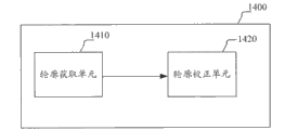
图14示出根据本发明的一个实施例的运动对象轮廓提取装置的示意性框图。如图14所示,运动对象轮廓提取装置1400包括轮廓获取单元1410和轮廓校正单元1420。轮廓获取单元1410用于获取运动对象在每个图像片中的轮廓。轮廓校正单元1420用于基于运动对象在各个图像片时间序列中的运动趋势信息来校正运动对象在至少一个图像片时间序列中的图像片中的轮廓。Fig. 14 shows a schematic block diagram of an apparatus for extracting contours of moving objects according to an embodiment of the present invention. As shown in FIG. 14 , the moving object
这里,可以使用各种已有方法来获取运动对象的轮廓。作为示例,图15示出根据本发明的一个实施例的轮廓获取单元的示意性框图。如图15所示,轮廓获取单元1500包括运动区域检测单元1510、运动区域调整单元1520和运动对象识别单元1530。运动区域检测单元1510用于基于每个图像片时间序列中像素的值随时间的变化来检测图像片时间序列的运动区域。运动区域调整单元1520用于以三维图像时间序列中预定图像片时间序列的运动区域为基准来调整三维图像时间序列中其他图像片时间序列的运动区域。具体地,运动区域调整单元1520可以使用关于图2中的步骤S220所描述的方法来调整运动区域。运动对象识别单元1530从每个图像片时间序列的运动区域中识别出运动对象的候选区域,以运动对象的候选区域的轮廓作为运动对象的轮廓。Here, various existing methods can be used to obtain the contour of the moving object. As an example, Fig. 15 shows a schematic block diagram of a contour acquisition unit according to an embodiment of the present invention. As shown in FIG. 15 , the
根据本发明的一个实施例,可以利用从每个图像片时间序列的运动区域提取的特征来确定上述将在运动区域调整单元1620中使用的预定图像片时间序列。图16示出根据本发明的该实施例的轮廓获取单元的示意性框图。如图16所示,轮廓获取单元1600包括运动区域检测单元1610、运动区域调整单元1620、运动对象识别单元1630和分类单元1640。According to an embodiment of the present invention, the feature extracted from the motion area of each image slice time series can be used to determine the predetermined image slice time series to be used in the motion
运动区域检测单元1610、运动区域调整单元1620和运动对象识别单元1630基本上与图15中所示的轮廓获取单元1500中包括的运动区域检测单元1510、运动区域调整单元1520和运动对象识别单元1530相同,这里不再赘述。The motion
分类单元1640用于利用从每个图像片时间序列的运动区域提取的下述特征中的至少一个来确定将在运动区域调整单元1620中使用的预定图像片时间序列:像素均值,运动区域的二值化图像中的白连通域比率,图像片索引,运动区域的二值化图像中的多个子区域的白连通域比率。作为一种具体实施方式,分类单元1640可以利用在以上的运动对象轮廓提取方法的实施例中描述的机器学习方法来确定上述预定图像片时间序列。The
根据本发明的另一个实施例,轮廓获取单元具有与图16所示的轮廓获取单元1600基本相同的结构,只是分类单元可以用于利用从每个图像片时间序列的运动区域提取的下述特征中的至少一个来确定分别与运动对象的两个端部对应的两个图像片时间序列:像素均值,运动区域的二值化图像中的白连通域比率,图像片索引,运动区域的二值化图像中的多个子区域的白连通域比率。在该实施例中,轮廓获取单元可以获取运动对象在位于两个图像片时间序列之间的图像片时间序列中的图像片中的轮廓,而不是针对所有图像片时间序列获取运动对象的轮廓。According to another embodiment of the present invention, the contour acquisition unit has basically the same structure as the
在获取了运动对象的轮廓之后,基于运动对象的运动趋势信息来校正运动对象的轮廓。图17示出根据本发明的一个实施例的轮廓校正单元的示意性框图。如图17所示,轮廓校正单元1700包括运动趋势确定单元1710、相似度计算单元1720和校正执行单元1730。After the contour of the moving object is acquired, the contour of the moving object is corrected based on the motion trend information of the moving object. Fig. 17 shows a schematic block diagram of a contour correction unit according to an embodiment of the present invention. As shown in FIG. 17 , the
运动趋势确定单元1710用于确定运动对象在各个图像片时间序列中的运动趋势信息。The motion
相似度计算单元1720用于计算运动对象在每个图像片时间序列中的运动趋势信息与运动对象的基准运动趋势信息的相似度。根据本发明的一个实施例,相似度计算单元1720被配置为计算运动对象在各个图像片时间序列中的平均运动趋势信息作为运动对象的基准运动趋势信息,或者将运动对象在预先被确定为模板的图像片时间序列中的运动趋势信息作为运动对象的基准运动趋势信息。另外,相似度计算单元1720可以使用以上在图5中的步骤S520中描述的相似度计算方法例如归一化互相关算法来计算相似度。The
校正执行单元1730用于:如果运动对象在特定图像片时间序列中的运动趋势信息与基准运动趋势信息的相似度低于预定阈值,则校正运动对象在所述特定图像片时间序列中的图像片中的轮廓。根据本发明的一个实施例,可以利用运动对象在与所述特定图像片时间序列相邻的图像片时间序列中的图像片中的轮廓来校正运动对象在所述特定图像片时间序列中的图像片中的轮廓。根据本发明的另一个实施例,如果经过校正后运动对象在特定图像片时间序列中的运动趋势信息与基准运动趋势信息的相似度仍低于预定阈值,则校正执行单元1730从三维图像时间序列中去除所述特定图像片时间序列。The
关于运动对象轮廓提取装置中每个部件的更多详细操作,可以参考以上对根据本发明实施例的运动对象轮廓提取方法的描述,这里不再重复。For more detailed operations of each component in the moving object contour extraction device, reference may be made to the above description of the moving object contour extraction method according to the embodiment of the present invention, which will not be repeated here.
在根据本发明实施例的运动对象轮廓提取装置中,利用运动对象的运动趋势来校正运动对象的轮廓,使得运动对象的变形转变为有利因素,帮助发现并去除可能有误的轮廓。另外,通过以受干扰最小的预定图像片时间序列的运动区域为基准来调整其他图像片时间序列的运动区域,可以消除奇特图像片时间序列中的干扰的影响。此外,通过确定三维图像时间序列中对应于运动对象的两端的图像片时间序列,可以不对位于运动对象两端之外的图像片时间序列进行轮廓提取,以减小计算量,并避免对这些图像片时间序列的提取结果对后续处理产生不良影响。另外,基于运动区域的至少一个特征,利用机器学习方法如SVM分类器等能够较为准确地确定三维图像时间序列中对应于运动对象的两端的图像片时间序列。In the apparatus for extracting the contour of a moving object according to an embodiment of the present invention, the movement tendency of the moving object is used to correct the contour of the moving object, so that the deformation of the moving object becomes an advantageous factor, helping to find and remove possible erroneous contours. In addition, by adjusting the motion areas of other image slice time series based on the motion area of the predetermined image slice time series with the least interference, the influence of interference in the strange image slice time series can be eliminated. In addition, by determining the time series of image slices corresponding to the two ends of the moving object in the three-dimensional image time series, it is possible not to perform contour extraction on the time series of image slices located outside the two ends of the moving object, so as to reduce the amount of calculation and avoid The extraction results of slice time series have adverse effects on subsequent processing. In addition, based on at least one feature of the moving region, a machine learning method such as an SVM classifier can be used to more accurately determine the time series of image slices corresponding to both ends of the moving object in the time series of three-dimensional images.
<4.左心室图像分割装置><4. Left ventricular image segmentation device>
以下结合图18-21来描述根据本发明实施例的左心室图像分割装置。所述左心室图像分割装置用于从三维医学图像时间序列获取左心室的轮廓,所述三维医学图像时间序列包括分别在至少包括一个心动周期的时间段中的多个时刻获得的多个三维图像,每个三维图像由与所述左心室的长轴相交的多个平行二维图像片构成,且在所述多个三维图像中同一位置的多个二维图像片构成一个图像片时间序列。The left ventricle image segmentation device according to the embodiment of the present invention will be described below with reference to FIGS. 18-21 . The left ventricle image segmentation device is used to obtain the outline of the left ventricle from a time series of three-dimensional medical images, the time series of three-dimensional medical images includes a plurality of three-dimensional images respectively obtained at a plurality of moments in a time period including at least one cardiac cycle Each three-dimensional image is composed of multiple parallel two-dimensional image slices intersecting the long axis of the left ventricle, and multiple two-dimensional image slices at the same position in the multiple three-dimensional images form a time sequence of image slices.
图18示出根据本发明的一个实施例的左心室图像分割装置的示意性框图。如图18所示,左心室图像分割装置1800包括极点获取单元1810、坐标变换单元1820和心内膜轮廓获取单元1830。极点获取单元1810用于获取每个图像片中用于极坐标变换的极点。坐标变换单元1820用于基于每个图像片中的极点将图像片变换到极坐标系中,以及将心内膜轮廓获取单元1830获取的左心室的轮廓映射到相应的原始图像片中。心内膜轮廓获取单元1830用于在极坐标系中获取左心室在每个图像片中的心内膜轮廓,作为左心室在所述图像片中的轮廓。Fig. 18 shows a schematic block diagram of a left ventricle image segmentation device according to an embodiment of the present invention. As shown in FIG. 18 , the left ventricular
极点可以人工标注,也可以通过现有技术中适合的方法确定。图19示出根据本发明的一个实施例的极点获取单元的示意性框图。其中,极点获取单元1900包括运动对象轮廓提取单元1910和极点确定单元1920。运动对象提取单元1910用于从三维医学图像时间序列中提取左心室的轮廓作为左心室的初始轮廓。可以以左心室作为运动对象,使用根据本发明实施例的运动对象轮廓提取装置来实施运动对象轮廓提取单元1910。极点确定单元1920被配置为确定左心室在每个图像片中的初始轮廓的中心,作为所述图像片中的极点。The poles can be marked manually, or can be determined by a suitable method in the prior art. Fig. 19 shows a schematic block diagram of a pole acquisition unit according to an embodiment of the present invention. Wherein, the
心内膜轮廓获取单元1830可以利用现有的任意合适方法来在极坐标系中获取左心室在每个图像片中的心内膜轮廓。The endocardial
根据本发明的一个实施例,坐标变换单元1820还被配置为基于每个图像片中的极点将极点获取单元1900中的运动对象轮廓提取单元1910获得的左心室在每个图像片中的初始轮廓变换到极坐标系中;心内膜轮廓获取单元1830还被配置为在极坐标系中对每个图像片中的初始轮廓进行平滑以得到图像片中的心内膜轮廓。例如,心内膜轮廓获取单元1830可以利用Hough变换方法来平滑左心室在每个图像片中的初始轮廓。这样,可以基于运动对象轮廓提取单元1910获得的左心室的初始轮廓来得到最终的心内膜轮廓。According to an embodiment of the present invention, the coordinate
根据本发明的另一实施例,心内膜轮廓获取单元1830可以利用图像片的水平投影来确定心内膜轮廓在极坐标系中的大致位置,然后用直线检测方法从图像片的边缘图像中获得心内膜轮廓。图20示出根据本发明的另一个实施例的左心室图像分割装置的示意性框图。在图20中,左心室图像分割装置2000包括极点获取单元2010、坐标变换单元2020、心内膜轮廓获取单元2030和边缘检测单元2040。其中,极坐标获取单元2010和坐标变换单元2020与图18中所示的极坐标获取单元1810和坐标变换单元1820基本上相同。边缘检测单元2040用于检测每个图像片中的边缘。应当理解,边缘检测单元2040可以在极坐标系中检测每个图像片的边缘,也可以在欧几里德坐标系中检测每个图像片的边缘,然后将边缘图像变换到极坐标系中。心内膜轮廓获取单元2030在图18所示的心内膜轮廓获取单元1830的基础上被进一步配置为:在极坐标系中利用每个图像片的灰度图像的水平投影来获取左心室在每个图像片中的心内膜轮廓的半径;以及在极坐标系中利用直线检测方法从位于左心室的心内膜轮廓的半径附近的边缘获得左心室的心内膜轮廓。According to another embodiment of the present invention, the endocardial
根据本发明的另一实施例,在使用根据本发明实施例的运动对象轮廓提取装置来实施运动对象轮廓提取单元1910的情况下,心内膜轮廓获取单元2030还可以通过以下方式来获得心内膜轮廓:在极坐标系中利用每个图像片的灰度图像的水平投影来获取左心室在每个图像片中的心内膜轮廓的第一半径;基于左心室在每个图像片中的初始轮廓来获取左心室在每个图像片中的心内膜轮廓的第二半径;以及在极坐标系中利用直线检测方法从位于左心室的心内膜轮廓的第一半径与第二半径的平均位置附近的边缘获得左心室的心内膜轮廓。According to another embodiment of the present invention, when the moving object
在上述实施例中,心内膜轮廓提取装置使用的直线检测方法可以是Hough变换方法。In the above embodiments, the straight line detection method used by the endocardial contour extraction device may be a Hough transform method.
为了进一步获取左心室的心外膜的轮廓,根据本发明实施例的左心室图像分割装置还可以包括心外膜轮廓获取单元。图21示出根据本发明的又一个实施例的左心室图像分割装置的示意性框图。如图21所示,左心室图像分割装置2100包括极点获取单元2110、坐标变换单元2120、心内膜轮廓获取单元2130、边缘检测单元2140和心外膜轮廓获取单元2150。其中,极点获取单元2110、坐标变换单元2120、心内膜轮廓获取单元2130与图18中所示的极点获取单元1810、坐标变换单元1820和心内膜轮廓获取单元2130基本上相同。边缘检测单元2140用于检测每个图像片中的边缘。心外膜轮廓获取单元2150用于获取左心室的心外膜的轮廓。具体而言,心内膜轮廓获取单元2130还被配置用于在极坐标系中利用每个图像片的灰度图像的水平投影来获取左心室在每个图像片中的心内膜轮廓的半径。心外膜轮廓获取单元2150被配置用于:在极坐标系中利用每个图像片的边缘图像的水平投影和左心室在该图像片中的心内膜轮廓的半径来获取左心室在每个图像片中的心外膜轮廓的半径;以及在极坐标系中利用曲线拟合方法从位于左心室的心外膜轮廓的半径附近的边缘获得左心室的心外膜轮廓。另外,为了将得到的心外膜轮廓形象地呈现给用户,坐标变换单元2120还被配置为将左心室的心外膜轮廓映射到相应的原始图像片中。In order to further obtain the contour of the epicardium of the left ventricle, the left ventricle image segmentation apparatus according to the embodiment of the present invention may further include an epicardial contour obtaining unit. Fig. 21 shows a schematic block diagram of a left ventricle image segmentation device according to yet another embodiment of the present invention. As shown in FIG. 21 , the left ventricular
此外,根据本发明的一个实施例,当利用根据本发明实施例的运动对象轮廓提取装置来左心室图像分割装置中的极点获取单元中的运动对象轮廓提取单元时,运动对象轮廓提取装置中的运动对象识别单元根据每个图像片时间序列的运动区域的多个图形特征以及左心室的估计中心位置来从图像片时间序列的运动区域中识别出左心室的候选区域。对左心室的估计中心位置可以具有比所述多个图形特征更大的权重。In addition, according to an embodiment of the present invention, when using the moving object contour extraction device according to the embodiment of the present invention to extract the moving object contour extraction unit in the pole acquisition unit in the left ventricle image segmentation device, the moving object contour extraction unit in the moving object contour extraction device The moving object recognition unit identifies a candidate region of the left ventricle from the moving regions of the time series of image slices according to multiple graphic features of the moving regions of each image slice time series and the estimated central position of the left ventricle. The estimated central location of the left ventricle may have greater weight than the plurality of graphical features.
关于左心室图像分割装置中每个部件的更多详细操作,可以参考以上对根据本发明实施例的左心室图像分割方法的描述和对运动对象轮廓提取方法中的相关描述,这里不再重复。For more detailed operations of each component in the left ventricle image segmentation device, reference can be made to the above description of the left ventricle image segmentation method according to the embodiment of the present invention and the related description of the moving object contour extraction method, which will not be repeated here.
在根据本发明实施例的左心室图像分割装置中,将原始图像片转换到极坐标系中,使得原本是曲线的心内膜轮廓呈现为近似直线,原本模糊的心外膜轮廓相对清楚,从而能够更准确地从图像片中分割出左心室。另外,在极坐标系中使用Hough变换等对心内膜的初始轮廓进行平滑或者使用例如Hough变换等直线检测方法从心内膜的边缘像素点拟合出心内膜轮廓,能够消除乳头肌的影响。此外,利用图像片在水平方向上的投影,能够准确地确定出心内膜轮廓和心外膜轮廓所在的大致位置。In the left ventricular image segmentation device according to the embodiment of the present invention, the original image slice is converted into the polar coordinate system, so that the originally curved endocardial contour appears as an approximate straight line, and the originally fuzzy epicardial contour is relatively clear, so that The left ventricle can be more accurately segmented from the image slice. In addition, in the polar coordinate system, use Hough transform to smooth the initial contour of the endocardium, or use a straight line detection method such as Hough transform to fit the endocardial contour from the edge pixels of the endocardium, which can eliminate the loss of papillary muscle. Influence. In addition, by using the projection of the image slices in the horizontal direction, the approximate positions of the endocardial contour and the epicardial contour can be accurately determined.
<5.可实施本公开的方法/装置的计算机结构><5. Computer structure capable of implementing the method/apparatus of the present disclosure>
作为一个示例,上述运动对象轮廓提取方法的各个步骤以及上述运动对象轮廓提取装置的各个组成模块和/或单元可以实施为医疗诊断装置(如X射线诊断装置、UL诊断装置、CT装置、MRI诊断装置或PET装置等)中的软件、固件、硬件或其组合,并作为该医疗诊断装置中的一部分。作为一个示例,上述左心室图像分割方法的各个步骤以及上述左心室图像分割装置的各个组成模块和/或单元可以实施为医疗诊断装置(如MRI诊断装置等)中的软件、固件、硬件或其组合,并作为该医疗诊断装置中的一部分。作为一个示例,可以在已有医疗诊断装置中实施根据本公开的上述方法和/或设备,其中对已有医疗诊断装置的各组成部分作一定修改即可。作为另一示例,上述方法的各个步骤以及上述设备的各个组成模块和/或单元可以实施为独立于所述医疗诊断装置的装置。上述设备中各个组成模块、单元通过软件、固件、硬件或其组合的方式进行配置时可使用的具体手段或方式为本领域技术人员所熟知,在此不再赘述。As an example, each step of the above-mentioned moving object contour extraction method and each component module and/or unit of the above-mentioned moving object contour extraction device can be implemented as a medical diagnostic device (such as an X-ray diagnostic device, a UL diagnostic device, a CT device, an MRI diagnostic device, etc.) device or PET device, etc.) as part of the medical diagnostic device. As an example, each step of the above left ventricular image segmentation method and each component module and/or unit of the above left ventricular image segmentation device can be implemented as software, firmware, hardware or other components in a medical diagnostic device (such as MRI diagnostic device, etc.). Combination, and as a part of the medical diagnostic device. As an example, the above-mentioned method and/or device according to the present disclosure can be implemented in an existing medical diagnostic device, where certain modifications to the components of the existing medical diagnostic device are sufficient. As another example, each step of the above-mentioned method and each component module and/or unit of the above-mentioned device may be implemented as a device independent of the medical diagnostic device. The specific means or methods that can be used when each component module and unit in the above-mentioned device are configured by means of software, firmware, hardware or a combination thereof are well known to those skilled in the art, and will not be repeated here.
作为一个示例,上述方法的各个步骤以及上述设备的各个组成模块和/或单元可以实施为软件、固件、硬件或其组合。在通过软件或固件实现的情况下,可以从存储介质或网络向具有专用硬件结构的计算机(例如图22所示的通用计算机2200)安装构成用于实施上述方法的软件的程序,该计算机在安装有各种程序时,能够执行各种功能等。As an example, each step of the above method and each component module and/or unit of the above device may be implemented as software, firmware, hardware or a combination thereof. In the case of realizing by software or firmware, a computer having a dedicated hardware structure (such as a general-
在图22中,运算处理单元(即CPU)2201根据只读存储器(ROM)2202中存储的程序或从存储部分2208加载到随机存取存储器(RAM)2203的程序执行各种处理。在RAM 2203中,也根据需要存储当CPU 2201执行各种处理等等时所需的数据。CPU 2201、ROM 2202和RAM 2203经由总线2204彼此链路。输入/输出接口2205也链路到总线2204。In FIG. 22 , an arithmetic processing unit (ie, CPU) 2201 executes various processes according to programs stored in a read only memory (ROM) 2202 or loaded from a
下述部件链路到输入/输出接口2205:输入部分2206(包括键盘、鼠标等等)、输出部分2207(包括显示器,比如阴极射线管(CRT)、液晶显示器(LCD)等,和扬声器等)、存储部分2208(包括硬盘等)、通信部分2209(包括网络接口卡比如LAN卡、调制解调器等)。通信部分2209经由网络比如因特网执行通信处理。根据需要,驱动器2210也可链路到输入/输出接口2205。可拆卸介质2211比如磁盘、光盘、磁光盘、半导体存储器等等根据需要被安装在驱动器2210上,使得从中读出的计算机程序根据需要被安装到存储部分2208中。The following components are linked to the input/output interface 2205: an input section 2206 (including a keyboard, a mouse, etc.), an output section 2207 (including a display, such as a cathode ray tube (CRT), a liquid crystal display (LCD), etc., and a speaker, etc.) , a storage part 2208 (including a hard disk, etc.), a communication part 2209 (including a network interface card such as a LAN card, a modem, etc.). The
在通过软件实现上述系列处理的情况下,从网络比如因特网或存储介质比如可拆卸介质2211安装构成软件的程序。In the case of realizing the above-described series of processing by software, the programs constituting the software are installed from a network such as the Internet or a storage medium such as the
本领域的技术人员应当理解,这种存储介质不局限于图22所示的其中存储有程序、与设备相分离地分发以向用户提供程序的可拆卸介质2211。可拆卸介质2211的例子包含磁盘(包含软盘(注册商标))、光盘(包含光盘只读存储器(CD-ROM)和数字通用盘(DVD))、磁光盘(包含迷你盘(MD)(注册商标))和半导体存储器。或者,存储介质可以是ROM 2202、存储部分2208中包含的硬盘等等,其中存有程序,并且与包含它们的设备一起被分发给用户。Those skilled in the art should understand that such a storage medium is not limited to the removable medium 2211 shown in FIG. 22 in which the program is stored and distributed separately from the device to provide the program to the user. Examples of the
本公开还提出一种存储有机器可读取的指令代码的程序产品。所述指令代码由机器读取并执行时,可执行上述根据本公开实施例的方法。The present disclosure also proposes a program product storing machine-readable instruction codes. When the instruction code is read and executed by a machine, the above-mentioned method according to the embodiments of the present disclosure can be executed.
相应地,用于承载上述存储有机器可读取的指令代码的程序产品的存储介质也包括在本公开的公开中。所述存储介质包括但不限于软盘、光盘、磁光盘、存储卡、存储棒等等。Correspondingly, a storage medium for carrying the program product storing the above-mentioned machine-readable instruction codes is also included in the disclosure of the present disclosure. The storage medium includes, but is not limited to, a floppy disk, an optical disk, a magneto-optical disk, a memory card, a memory stick, and the like.
在上面对本公开具体实施例的描述中,针对一种实施方式描述和/或示出的特征可以用相同或类似的方式在一个或更多个其它实施方式中使用,与其它实施方式中的特征相组合,或替代其它实施方式中的特征。In the above description of specific embodiments of the present disclosure, features described and/or illustrated for one embodiment can be used in one or more other embodiments in the same or similar manner, and features in other embodiments Combination or replacement of features in other embodiments.
应该强调,术语“包括/包含”在本文使用时指特征、要素、步骤或组件的存在,但并不排除一个或更多个其它特征、要素、步骤或组件的存在或附加。It should be emphasized that the term "comprising/comprising" when used herein refers to the presence of a feature, element, step or component, but does not exclude the presence or addition of one or more other features, elements, steps or components.
在上述实施例和示例中,采用了数字组成的附图标记来表示各个步骤和/或单元。本领域的普通技术人员应理解,这些附图标记只是为了便于叙述和绘图,而并非表示其顺序或任何其他限定。In the above embodiments and examples, reference numerals composed of numbers are used to represent various steps and/or units. Those skilled in the art should understand that these reference numerals are only for convenience of description and drawing, and do not represent their order or any other limitation.
此外,本公开的方法不限于按照说明书中描述的时间顺序来执行,也可以按照其他的时间顺序地、并行地或独立地执行。因此,本说明书中描述的方法的执行顺序不对本公开的技术范围构成限制。In addition, the methods of the present disclosure are not limited to being performed in the chronological order described in the specification, and may also be performed in other chronological order, in parallel or independently. Therefore, the execution order of the methods described in this specification does not limit the technical scope of the present disclosure.
尽管上面已经通过对本公开的具体实施例的描述对本公开进行了披露,但是,应该理解,上述的所有实施例和示例均是示例性的,而非限制性的。本领域的技术人员可在所附权利要求的精神和范围内设计对本公开的各种修改、改进或者等同物。这些修改、改进或者等同物也应当被认为包括在本公开的保护范围内。Although the present disclosure has been disclosed above by describing specific embodiments of the present disclosure, it should be understood that all the above-mentioned embodiments and examples are illustrative rather than restrictive. Various modifications, improvements, or equivalents to the present disclosure may be devised by those skilled in the art within the spirit and scope of the appended claims. These modifications, improvements or equivalents should also be considered to be included in the protection scope of the present disclosure.
Claims (39)
Priority Applications (4)
| Application Number | Priority Date | Filing Date | Title |
|---|---|---|---|
| CN201110209867.4A CN102890823B (en) | 2011-07-19 | 2011-07-19 | Motion object outline is extracted and left ventricle image partition method and device |
| JP2012159856A JP2013022463A (en) | 2011-07-19 | 2012-07-18 | Moving object contour extraction apparatus, left ventricle image separation apparatus, moving object contour extraction method and left ventricle image separation method |
| US13/553,022 US9314161B2 (en) | 2011-07-19 | 2012-07-19 | Moving object contour extraction apparatus, left ventricle image segmentation apparatus, moving object contour extraction method and left ventricle image segmentation method |
| EP12177159.6A EP2549437B1 (en) | 2011-07-19 | 2012-07-19 | Moving object contour extraction apparatus, left ventricle image segmentation apparatus, moving object contour extraction method and left ventricle image segmentation |
Applications Claiming Priority (1)
| Application Number | Priority Date | Filing Date | Title |
|---|---|---|---|
| CN201110209867.4A CN102890823B (en) | 2011-07-19 | 2011-07-19 | Motion object outline is extracted and left ventricle image partition method and device |
Publications (2)
| Publication Number | Publication Date |
|---|---|
| CN102890823A true CN102890823A (en) | 2013-01-23 |
| CN102890823B CN102890823B (en) | 2016-04-27 |
Family
ID=46578880
Family Applications (1)
| Application Number | Title | Priority Date | Filing Date |
|---|---|---|---|
| CN201110209867.4A Expired - Fee Related CN102890823B (en) | 2011-07-19 | 2011-07-19 | Motion object outline is extracted and left ventricle image partition method and device |
Country Status (4)
| Country | Link |
|---|---|
| US (1) | US9314161B2 (en) |
| EP (1) | EP2549437B1 (en) |
| JP (1) | JP2013022463A (en) |
| CN (1) | CN102890823B (en) |
Cited By (14)
| Publication number | Priority date | Publication date | Assignee | Title |
|---|---|---|---|---|
| CN105260997A (en) * | 2015-09-22 | 2016-01-20 | 北京好运到信息科技有限公司 | Method for automatically obtaining target image |
| CN105705098A (en) * | 2013-09-20 | 2016-06-22 | 透壁生物技术公司 | Image analysis techniques for diagnosing diseases |
| CN107616803A (en) * | 2016-07-13 | 2018-01-23 | 西门子保健有限责任公司 | Pass through the magnetic resonance of combination and the method for X-ray device collection and processing measurement data |
| CN108352067A (en) * | 2015-11-19 | 2018-07-31 | 皇家飞利浦有限公司 | User's interaction in Optimized Segmentation |
| EP3245615A4 (en) * | 2014-11-18 | 2018-10-17 | Padubrin, Harry Friedbert | Learning contour identification system using portable contour metrics derived from contour mappings |
| CN108968996A (en) * | 2017-05-30 | 2018-12-11 | 通用电气公司 | Motion gate medical imaging |
| CN109394269A (en) * | 2018-12-08 | 2019-03-01 | 余姚市华耀工具科技有限公司 | Cardiac objects are highlighted platform |
| CN109685816A (en) * | 2018-12-27 | 2019-04-26 | 上海联影医疗科技有限公司 | Image segmentation method, device, equipment and storage medium |
| CN110073408A (en) * | 2016-12-12 | 2019-07-30 | 皇家飞利浦有限公司 | Method and apparatus for segmenting two-dimensional images of anatomical structures |
| CN110244314A (en) * | 2019-06-24 | 2019-09-17 | 北京机械设备研究所 | One kind " low slow small " target acquisition identifying system and method |
| CN111783529A (en) * | 2019-07-26 | 2020-10-16 | 牧今科技 | Post-detection improvement based on edges and multi-dimensional corners |
| CN112419276A (en) * | 2020-11-25 | 2021-02-26 | 苏州润迈德医疗科技有限公司 | Method for regulating blood vessel contour and central line and storage medium |
| CN113108921A (en) * | 2021-04-19 | 2021-07-13 | 巴斯夫新材料有限公司 | Method, device and system for monitoring the temperature of an object |
| US11389965B2 (en) | 2019-07-26 | 2022-07-19 | Mujin, Inc. | Post-detection refinement based on edges and multi-dimensional corners |
Families Citing this family (21)
| Publication number | Priority date | Publication date | Assignee | Title |
|---|---|---|---|---|
| JP5347003B2 (en) * | 2011-09-30 | 2013-11-20 | 富士フイルム株式会社 | Medical image processing apparatus and method, and program |
| CN104156975B (en) * | 2013-05-13 | 2018-04-24 | 东芝医疗系统株式会社 | Medical image analysis apparatus and method and medical imaging devices |
| JP6191328B2 (en) * | 2013-08-19 | 2017-09-06 | コニカミノルタ株式会社 | Ultrasonic diagnostic apparatus, ultrasonic image analysis method, and program |
| US10121254B2 (en) | 2013-08-29 | 2018-11-06 | Disney Enterprises, Inc. | Methods and systems of detecting object boundaries |
| KR101616029B1 (en) * | 2014-07-25 | 2016-04-27 | 삼성전자주식회사 | Magnetic resonance imaging processing method and apparatus thereof |
| DE102015205270A1 (en) * | 2015-03-24 | 2016-09-29 | Siemens Healthcare Gmbh | Method for determining an X-ray image data set of a moving target area and X-ray device |
| US10290109B2 (en) * | 2015-12-22 | 2019-05-14 | Shanghai United Imaging Healthcare Co., Ltd. | Method and system for cardiac image segmentation |
| CN106910194B (en) * | 2015-12-22 | 2020-11-27 | 上海联影医疗科技股份有限公司 | Segmentation method of epicardium and epicardium in cardiac functional magnetic resonance images |
| US10089554B1 (en) * | 2016-03-30 | 2018-10-02 | Descartes Labs, Inc. | Creating a boundary map |
| JP7184489B2 (en) * | 2016-09-18 | 2022-12-06 | イェダ リサーチ アンド ディベロップメント カンパニー リミテッド | Systems and methods for generating 3D images based on fluorescent illumination |
| JP6815259B2 (en) * | 2017-03-31 | 2021-01-20 | キヤノンメディカルシステムズ株式会社 | Ultrasound diagnostic equipment, medical image processing equipment and medical image processing programs |
| US20190021677A1 (en) * | 2017-07-18 | 2019-01-24 | Siemens Healthcare Gmbh | Methods and systems for classification and assessment using machine learning |
| JP6885260B2 (en) * | 2017-08-10 | 2021-06-09 | コニカミノルタ株式会社 | Dynamic image analyzer |
| CN108648195B (en) * | 2018-05-09 | 2022-06-28 | 联想(北京)有限公司 | Image processing method and device |
| WO2020048928A1 (en) * | 2018-09-05 | 2020-03-12 | Norwegian University Of Science And Technology (Ntnu) | Functional measurements in echocardiography |
| CN109919027A (en) * | 2019-01-30 | 2019-06-21 | 合肥特尔卡机器人科技股份有限公司 | A kind of Feature Extraction System of road vehicles |
| CN110298901B (en) * | 2019-06-25 | 2023-07-04 | 沈阳东软智能医疗科技研究院有限公司 | Magnetic resonance image correction method, device, storage medium and equipment |
| CN110428431B (en) * | 2019-07-12 | 2022-12-16 | 广东省人民医院(广东省医学科学院) | Method, device and equipment for segmenting cardiac medical image and storage medium |
| JP7780875B2 (en) | 2021-05-07 | 2025-12-05 | キヤノンメディカルシステムズ株式会社 | Medical image processing device, ultrasound diagnostic device, and program |
| CN114898256B (en) * | 2022-04-28 | 2025-01-03 | 重庆中科云从科技有限公司 | Target object detection method, device and computer storage medium |
| CN120543579B (en) * | 2025-07-28 | 2025-11-14 | 深圳市星火数控技术有限公司 | Image edge contour extraction method and device, electronic equipment and storage medium |
Citations (4)
| Publication number | Priority date | Publication date | Assignee | Title |
|---|---|---|---|---|
| CN1683939A (en) * | 2004-04-13 | 2005-10-19 | 西门子公司 | A multipoint approach to motion correction for fusion-weighted imaging in magnetic resonance tomography |
| JP2009261638A (en) * | 2008-04-25 | 2009-11-12 | Toshiba Medical Systems Corp | Ultrasonic diagnostic device, ultrasonic image processor, and ultrasonic image processing program |
| US20100201687A1 (en) * | 2007-09-03 | 2010-08-12 | Koninklijke Philips Electronics N.V. | Visualization of voxel data |
| CN101807296A (en) * | 2009-02-16 | 2010-08-18 | 海信集团有限公司 | Segmentation method of medical ultrasonic image three-dimensional target object |
Family Cites Families (13)
| Publication number | Priority date | Publication date | Assignee | Title |
|---|---|---|---|---|
| US5570430A (en) * | 1994-05-31 | 1996-10-29 | University Of Washington | Method for determining the contour of an in vivo organ using multiple image frames of the organ |
| US6708055B2 (en) * | 1998-08-25 | 2004-03-16 | University Of Florida | Method for automated analysis of apical four-chamber images of the heart |
| US6728566B1 (en) * | 2001-11-21 | 2004-04-27 | Koninklijke Philips Electronics, N.V. | Vessel tracking and tree extraction method and apparatus |
| WO2007138522A1 (en) * | 2006-05-25 | 2007-12-06 | Koninklijke Philips Electronics N.V. | Quantification and display of cardiac chamber wall thickening |
| JP5414157B2 (en) * | 2007-06-06 | 2014-02-12 | 株式会社東芝 | Ultrasonic diagnostic apparatus, ultrasonic image processing apparatus, and ultrasonic image processing program |
| DE102008008601B4 (en) | 2008-02-12 | 2010-07-29 | Siemens Aktiengesellschaft | Method for processing medical image data for the layered imaging of a structure during free breathing |
| US8433113B2 (en) * | 2008-03-12 | 2013-04-30 | Siemens Aktiengesellschaft | Automatic recovery of the left ventricular blood pool in cardiac cine magnetic resonance images |
| US8218839B2 (en) | 2008-05-23 | 2012-07-10 | Siemens Aktiengesellschaft | Automatic localization of the left ventricle in cardiac cine magnetic resonance imaging |
| US8317705B2 (en) * | 2008-12-10 | 2012-11-27 | Tomtec Imaging Systems Gmbh | Method for generating a motion-corrected 3D image of a cyclically moving object |
| CA2705731A1 (en) | 2009-02-23 | 2010-08-23 | Sunnybrook Health Sciences Centre | Method for automatic segmentation of images |
| US8363974B2 (en) * | 2009-07-21 | 2013-01-29 | Qualcomm Incorporated | Block artifact reducer |
| US10321892B2 (en) * | 2010-09-27 | 2019-06-18 | Siemens Medical Solutions Usa, Inc. | Computerized characterization of cardiac motion in medical diagnostic ultrasound |
| CN102890824B (en) * | 2011-07-19 | 2015-07-29 | 株式会社东芝 | Method and device for contour tracking of moving object |
-
2011
- 2011-07-19 CN CN201110209867.4A patent/CN102890823B/en not_active Expired - Fee Related
-
2012
- 2012-07-18 JP JP2012159856A patent/JP2013022463A/en active Pending
- 2012-07-19 US US13/553,022 patent/US9314161B2/en not_active Expired - Fee Related
- 2012-07-19 EP EP12177159.6A patent/EP2549437B1/en not_active Not-in-force
Patent Citations (4)
| Publication number | Priority date | Publication date | Assignee | Title |
|---|---|---|---|---|
| CN1683939A (en) * | 2004-04-13 | 2005-10-19 | 西门子公司 | A multipoint approach to motion correction for fusion-weighted imaging in magnetic resonance tomography |
| US20100201687A1 (en) * | 2007-09-03 | 2010-08-12 | Koninklijke Philips Electronics N.V. | Visualization of voxel data |
| JP2009261638A (en) * | 2008-04-25 | 2009-11-12 | Toshiba Medical Systems Corp | Ultrasonic diagnostic device, ultrasonic image processor, and ultrasonic image processing program |
| CN101807296A (en) * | 2009-02-16 | 2010-08-18 | 海信集团有限公司 | Segmentation method of medical ultrasonic image three-dimensional target object |
Cited By (23)
| Publication number | Priority date | Publication date | Assignee | Title |
|---|---|---|---|---|
| CN105705098A (en) * | 2013-09-20 | 2016-06-22 | 透壁生物技术公司 | Image analysis techniques for diagnosing diseases |
| EP3245615A4 (en) * | 2014-11-18 | 2018-10-17 | Padubrin, Harry Friedbert | Learning contour identification system using portable contour metrics derived from contour mappings |
| CN105260997B (en) * | 2015-09-22 | 2019-02-01 | 北京医拍智能科技有限公司 | A kind of method of automatic acquisition target image |
| CN105260997A (en) * | 2015-09-22 | 2016-01-20 | 北京好运到信息科技有限公司 | Method for automatically obtaining target image |
| CN108352067A (en) * | 2015-11-19 | 2018-07-31 | 皇家飞利浦有限公司 | User's interaction in Optimized Segmentation |
| CN107616803B (en) * | 2016-07-13 | 2021-01-01 | 西门子保健有限责任公司 | Method for acquiring and processing measurement data by means of a combined magnetic resonance and X-ray device |
| CN107616803A (en) * | 2016-07-13 | 2018-01-23 | 西门子保健有限责任公司 | Pass through the magnetic resonance of combination and the method for X-ray device collection and processing measurement data |
| CN110073408B (en) * | 2016-12-12 | 2023-07-14 | 皇家飞利浦有限公司 | Method and apparatus for segmenting two-dimensional images of anatomical structures |
| CN110073408A (en) * | 2016-12-12 | 2019-07-30 | 皇家飞利浦有限公司 | Method and apparatus for segmenting two-dimensional images of anatomical structures |
| CN108968996A (en) * | 2017-05-30 | 2018-12-11 | 通用电气公司 | Motion gate medical imaging |
| CN109394269B (en) * | 2018-12-08 | 2021-12-10 | 沈阳鹏悦科技有限公司 | Cardiac target highlighting platform |
| CN109394269A (en) * | 2018-12-08 | 2019-03-01 | 余姚市华耀工具科技有限公司 | Cardiac objects are highlighted platform |
| CN109685816A (en) * | 2018-12-27 | 2019-04-26 | 上海联影医疗科技有限公司 | Image segmentation method, device, equipment and storage medium |
| CN109685816B (en) * | 2018-12-27 | 2022-05-13 | 上海联影医疗科技股份有限公司 | An image segmentation method, device, equipment and storage medium |
| CN110244314A (en) * | 2019-06-24 | 2019-09-17 | 北京机械设备研究所 | One kind " low slow small " target acquisition identifying system and method |
| CN111783529A (en) * | 2019-07-26 | 2020-10-16 | 牧今科技 | Post-detection improvement based on edges and multi-dimensional corners |
| US11389965B2 (en) | 2019-07-26 | 2022-07-19 | Mujin, Inc. | Post-detection refinement based on edges and multi-dimensional corners |
| US11850760B2 (en) | 2019-07-26 | 2023-12-26 | Mujin, Inc. | Post-detection refinement based on edges and multi-dimensional corners |
| US12243117B2 (en) | 2019-07-26 | 2025-03-04 | Mujin, Inc. | Post-detection refinement based on edges and multi-dimensional corners |
| CN112419276A (en) * | 2020-11-25 | 2021-02-26 | 苏州润迈德医疗科技有限公司 | Method for regulating blood vessel contour and central line and storage medium |
| CN112419276B (en) * | 2020-11-25 | 2023-12-05 | 苏州润迈德医疗科技有限公司 | Method for adjusting contour and center line of blood vessel and storage medium |
| CN113108921A (en) * | 2021-04-19 | 2021-07-13 | 巴斯夫新材料有限公司 | Method, device and system for monitoring the temperature of an object |
| CN113108921B (en) * | 2021-04-19 | 2023-11-24 | 巴斯夫新材料有限公司 | Methods, devices and systems for monitoring the temperature of objects |
Also Published As
| Publication number | Publication date |
|---|---|
| EP2549437A3 (en) | 2013-05-01 |
| CN102890823B (en) | 2016-04-27 |
| EP2549437A2 (en) | 2013-01-23 |
| US9314161B2 (en) | 2016-04-19 |
| US20130184570A1 (en) | 2013-07-18 |
| JP2013022463A (en) | 2013-02-04 |
| EP2549437B1 (en) | 2017-03-08 |
Similar Documents
| Publication | Publication Date | Title |
|---|---|---|
| CN102890823B (en) | Motion object outline is extracted and left ventricle image partition method and device | |
| CN102890824B (en) | Method and device for contour tracking of moving object | |
| Jolly | Automatic segmentation of the left ventricle in cardiac MR and CT images | |
| CN106611411B (en) | Method for segmenting ribs in medical image and medical image processing device | |
| US9129417B2 (en) | Method and system for coronary artery centerline extraction | |
| CN106340021B (en) | Blood vessel extraction method | |
| US8682074B2 (en) | Method for checking the segmentation of a structure in image data | |
| EP2916738B1 (en) | Lung, lobe, and fissure imaging systems and methods | |
| CN101933045B (en) | Automatic 3-d segmentation of the short-axis late-enhancement cardiac MRI | |
| EP1851722B1 (en) | Image processing device and method | |
| CN104424629B (en) | A kind of x-ray chest radiograph lung segmentation method and apparatus | |
| US8948484B2 (en) | Method and system for automatic view planning for cardiac magnetic resonance imaging acquisition | |
| CN106910194B (en) | Segmentation method of epicardium and epicardium in cardiac functional magnetic resonance images | |
| WO2019000455A1 (en) | Method and system for segmenting image | |
| US7929741B2 (en) | System and method for automated detection of mucus plugs within bronchial tree in MSCT images | |
| CN111028254B (en) | Left myocardium segmentation method based on cardiac cine magnetic resonance image | |
| Larrey-Ruiz et al. | Automatic image-based segmentation of the heart from CT scans | |
| Bosch et al. | Active appearance motion models for endocardial contour detection in time sequences of echocardiograms | |
| EP3437068B1 (en) | System and methods for diagnostic image analysis and image quality assessment | |
| Butakoff et al. | Left-ventricular epi-and endocardium extraction from 3D ultrasound images using an automatically constructed 3D ASM | |
| CN104680513B (en) | Method and apparatus for estimating ventricular volume | |
| Xiang et al. | Fast renal cortex localization by combining generalized hough transform and active appearance models | |
| Bosch et al. | quantitation techniques in 2D echocardiography |
Legal Events
| Date | Code | Title | Description |
|---|---|---|---|
| C06 | Publication | ||
| PB01 | Publication | ||
| C10 | Entry into substantive examination | ||
| SE01 | Entry into force of request for substantive examination | ||
| C14 | Grant of patent or utility model | ||
| GR01 | Patent grant | ||
| C41 | Transfer of patent application or patent right or utility model | ||
| TR01 | Transfer of patent right |
Effective date of registration: 20160708 Address after: Japan Tochigi Tian Yuan City Patentee after: TOSHIBA MEDICAL SYSTEMS Corp. Address before: Tokyo, Japan Patentee before: Toshiba Corp. Patentee before: TOSHIBA MEDICAL SYSTEMS Corp. |
|
| CF01 | Termination of patent right due to non-payment of annual fee | ||
| CF01 | Termination of patent right due to non-payment of annual fee |
Granted publication date: 20160427 |