CN102806567A - Cantilever spring assist knife - Google Patents
Cantilever spring assist knife Download PDFInfo
- Publication number
- CN102806567A CN102806567A CN2012101792742A CN201210179274A CN102806567A CN 102806567 A CN102806567 A CN 102806567A CN 2012101792742 A CN2012101792742 A CN 2012101792742A CN 201210179274 A CN201210179274 A CN 201210179274A CN 102806567 A CN102806567 A CN 102806567A
- Authority
- CN
- China
- Prior art keywords
- blade
- utensil
- spring
- handle
- locking device
- Prior art date
- Legal status (The legal status is an assumption and is not a legal conclusion. Google has not performed a legal analysis and makes no representation as to the accuracy of the status listed.)
- Granted
Links
Images


Classifications
-
- B—PERFORMING OPERATIONS; TRANSPORTING
- B26—HAND CUTTING TOOLS; CUTTING; SEVERING
- B26B—HAND-HELD CUTTING TOOLS NOT OTHERWISE PROVIDED FOR
- B26B1/00—Hand knives with adjustable blade; Pocket knives
- B26B1/02—Hand knives with adjustable blade; Pocket knives with pivoted blade
- B26B1/04—Hand knives with adjustable blade; Pocket knives with pivoted blade lockable in adjusted position
- B26B1/046—Hand knives with adjustable blade; Pocket knives with pivoted blade lockable in adjusted position with a locking member acting in axial direction parallel to the pivot axis of the blade
Landscapes
- Life Sciences & Earth Sciences (AREA)
- Forests & Forestry (AREA)
- Engineering & Computer Science (AREA)
- Mechanical Engineering (AREA)
- Knives (AREA)
Abstract
A folding tool includes a handle and an implement pivotally coupled to the handle. The implement is adapted to travel between a closed position and an open position. The implement includes a tang having a contoured surface. The folding tool also includes a locking device movable between a locked position and an unlocked position along an axis that is transverse to a plane defined by the implement. The folding tool further includes a cantilever spring having a first end coupled to the handle and a second end adapted to interact with the tang of the implement. The spring exerts a closing force on the implement when the blade is in a closed position. The spring exerts an opening force on the implement during at least a portion of the travel of the implement between the closed position and the open position.
Description
Technical field
The present invention relates to folding cutter, particularly, the present invention relates to have that assisted user is opened the cantilever spring of this cutter and this cutter is locked in the folding cutter of the button class lock of open position.
Background technology
Folding cutter generally includes the blade of handle and one or more and this handle pivotal connection, and said blade has compact closing position and the open position of stretching out.In order to make the more useful and operation more easily of said cutter, add some supplementary features to folding cutter.Said characteristic can comprise and is used for the mechanism that assisted user is opened cutter, is used for blade is locked in the mechanism of open position, and blade is biased in the mechanism of closing position.The interpolation supplementary features have increased the cost and the complexity of folding cutter.For the folding cutter of moderate price sale, the consideration of cost possibly surpass the expectation to supplementary features for intention.Therefore, need a kind of mechanism that supplementary features are provided, and manufacturing cost can't be increased with accepting.And, need a kind of like this mechanism to use identical parts to carry out the function of multiple expectation.
The space that can otherwise be used for other purposes in the folding cutter of the needed element utilization of the category feature of realization such as assisting in opening function or blade lock function.Therefore, the mechanism of a kind of simplification of needs provides the characteristic of expectation but does not use big quantity space in the handle of a knife.
Expectation provides a kind of folding cutter, and it comprises the mechanism that possesses one or more these favorable characteristics or other favorable characteristics.According to this specification, it is obvious that other characteristic and advantage will become.Disclosed instruction extends to those embodiments that fall in the accompanying claims scope, and no matter they are to realize one or above the demand of realization.
Summary of the invention
One embodiment of the present invention relate to a kind of have handle and with the Foldable tool of the utensil of this handle pivotal connection.Said utensil is suitable between closing position and open position, moving.Said utensil comprises the tang with contour surface.Said Foldable tool also comprises locking device, and this locking device is removable between locked along the axle that crosses the plane that is limited in said utensil.Said Foldable tool also comprises having first end that is connected with said handle and the cantilever spring that is suitable for interactional second end of the tang of said utensil.Said spring applies closure function power to said utensil when utensil is in the close position.Said spring said utensil be in the close position and open position between partial journey at least in apply to said utensil and to open active force.
Another embodiment of the invention relate to a kind of have handle and with the folding cutter of the blade of this handle pivotal connection.Said blade has closing position and open position, and comprises the tang with contour surface.Said folding cutter also comprises locking device, this locking device along and the axle of the plane approximate vertical that limits said blade removable between locked.Said folding cutter also comprises the spring that is positioned at the plane that is limited on said blade.Said spring has the near-end that is connected with said handle and is suitable for through contacting the far-end that applies active force to said blade with said contour surface.
The present invention can have other embodiments and can implement in every way or carry out.Optional illustrative embodiments relates to other characteristics and combination of features, and these characteristics can briefly be described in the claim.
Description of drawings
According to following specifying, can understand the present invention more fully in conjunction with accompanying drawing, wherein similar Reference numeral refers to similar element, wherein:
Fig. 1 is the perspective view of the folding cutter that is shown in an open position of the blade according to a kind of illustrative embodiments;
Fig. 2 is the vertical view according to a kind of folding cutter shown in Figure 1 of illustrative embodiments;
Fig. 3 is the left view according to a kind of folding cutter shown in Figure 1 of illustrative embodiments;
Fig. 4 is the upward view according to a kind of folding cutter shown in Figure 1 of illustrative embodiments;
Fig. 5 is the right view according to a kind of folding cutter shown in Figure 1 of illustrative embodiments;
Fig. 6 is the front view according to a kind of folding cutter shown in Figure 1 of illustrative embodiments;
Fig. 7 is the rearview according to a kind of folding cutter shown in Figure 1 of illustrative embodiments;
Fig. 8 is the left view of the folding cutter shown in Figure 1 that is in the close position of the blade according to a kind of illustrative embodiments;
Fig. 9 is the cutaway view according to a kind of shown in Figure 3 folding cutter 9-9 along the line of illustrative embodiments;
Figure 10 is the cutaway view according to a kind of shown in Figure 8 folding cutter 10-10 along the line of illustrative embodiments;
Figure 11 is the exploded view according to a kind of folding cutter shown in Figure 1 of illustrative embodiments;
Figure 12 is the cut away left side view of the folding cutter shown in Figure 1 that is in the close position of the blade according to a kind of illustrative embodiments;
Figure 13 to Figure 15 is the cut away left side view of the folding cutter shown in Figure 1 that is in a partly opened position of the blade according to a kind of illustrative embodiments;
Figure 16 is that the blade according to a kind of illustrative embodiments is in a fully open position the cut away left side view with the folding cutter shown in Figure 1 of latched position;
Figure 17 to Figure 19 is the cut away left side view that is in the folding cutter shown in Figure 1 of part closing position according to a kind of blade of illustrative embodiments;
Figure 20 is the right view according to a kind of blade of folding cutter shown in Figure 1 of illustrative embodiments; And
Figure 21 is the cutaway view according to a kind of blade shown in Figure 20 21-21 along the line of illustrative embodiments;
Figure 22 is the left view according to the folding cutter of another illustrative embodiments;
Figure 23 is the vertical view according to a kind of folding cutter shown in Figure 22 of illustrative embodiments;
Figure 24 is the exploded view according to a kind of folding cutter shown in Figure 22 of illustrative embodiments;
Figure 25 is the cut away left side view of the folding cutter shown in Figure 22 that is in the close position of the blade according to a kind of illustrative embodiments;
Figure 26 to Figure 27 is the cut away left side view of the folding cutter shown in Figure 22 that is in a partly opened position of the blade according to a kind of illustrative embodiments;
Figure 28 is that the blade according to a kind of illustrative embodiments is in a fully open position the cut away left side view with the folding cutter shown in Figure 22 of latched position.
The specific embodiment
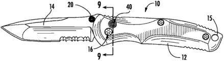
Referring to figs. 1 through Figure 21, show a kind of Foldable tool according to a kind of illustrative embodiments, be shown as folding cutter 10.Folding cutter 10 comprises handle 12, and handle 12 has first end with utensil (be shown as, but be not limited to, blade 14) pivotal connection.The blade shaft 16 of the tang 50 of blade 14 through extending through blade 14 is connected with handle 12.Thumb post 20 can stretch out from the part of blade and control for the user.According to a kind of illustrative embodiments, thumb screw or thumb post 20 comprise be configured to pass blade 14 (referring to, for example, the hole 11 in Figure 11) link together first or the recess 19 and second portion or protuberance 21 of (for example, tightening).To illustrative embodiments shown in Figure 21, handle 12 also comprises the opening in the lashing hole 15 of second end setting that is shown as adjacent hub 12 according to Fig. 1.
Shown in figure 11, according to a kind of illustrative embodiments, the handle 12 of folding cutter 10 comprises a pair of handle sidepiece, and it is shown as the first handle sidepiece 22 and the second handle sidepiece 24.The securing member that is shown as screw 37 is used for handle sidepiece 22,24 is linked together.Screw 37 extends through hole or the opening 25 on the handle sidepiece 22,24.According to a kind of illustrative embodiments, opening 25 has the beveled surface or the recessed surfaces of the head that holds each screw 37.The first pair of screw 37 is by being shown as member storage and second pair of screw 37 of first 38 by the member storage that is shown as second 39.Tube 38,39 has shape or the profile that roughly is the hourglass shape.The internal whorl that tube 38,39 also has receive screws 37 at relative separately two ends.Tube 38,39 is configured to handle sidepiece 22,24 is separated one section predetermined distance (for example, one section distance less times greater than blade 14 thickness).
According to a kind of illustrative embodiments, folding cutter 10 comprises that one of handle sidepiece with handle 12 (for example, handle sidepiece 22) connects the clip 26 of (for example, tightening).Clip 26 comprises the openend that is positioned at its first end and the parts or the flange 27 that are positioned at its second end.Flange 27 comprise be configured to take in be shown as screw 28 securing member clip 26 is connected to the pair of openings 29 of handle sidepiece 22.
Shown in figure 11, according to a kind of illustrative embodiments, axle 16 comprises first 17 and second portion 18.The opening 51 that first 17 and second portion 18 extend through on the handle sidepiece 22,24 opening 13 separately and extend through tang 50 is to be connected to handle 12 with blade 14 rotatably or pivotally.According to illustrative embodiments shown in Figure 11, second portion 18 is configured to be screwed into first 17.Yet according to other illustrative embodiments, first 17 can otherwise dispose with second portion 18.Opening 13 on the handle sidepiece 22,24 can also comprise the oblique cutting part or the recess of the head that holds first 17 and second portion 18.
According to a kind of illustrative embodiments, the part 33 through making expansion engages with the otch of inboard that is positioned at handle sidepiece 22,24 or inner surface or slit 23 (for example, recess, compartment, crack, otch etc.) spring 30 is connected to handle 12.Like this, first end 32 of spring 30 has the position with respect to handle 12 almost fixed, and the position of second end 34 changes according to the position of blade 14 is different.In other words, the position of second end 34 concrete rotation degree with blade 14 during open and close blade 14 changes.According to other illustrative embodiments, spring 30 can be connected to handle 12 with various structures.
According to a kind of illustrative embodiments, folding cutter 10 comprises latching/delatching mechanism, is shown as locking device 40 (for example, button latch, button class lock etc.).Locking device 40 is configured to interact with the locking/unlocking blade 14 from the fully open position with blade 14 (for example, the tang 50 of blade 14).Locking device 40 comprises the parts of the piston 42 that is shown as the hole 61 that extends through on the handle sidepiece 24.Piston 42 comprises first end 41 and second end 43.First end 41 can comprise a series of streaklines or the concentric ring on the outer surface of the exposure that is arranged on first end 41.These streaklines or concentric ring can help the user when the piston that pressure-locks device 40 42 (for example, with release locking device 40), suitably to locate finger or thumb.
According to a kind of illustrative embodiments, second end 43 of piston 42 forms cup 45, and this cup is configured to take in first end of the biasing member that is shown as helical spring 44.Second end of helical spring 44 is accommodated in the otch or the recess 63 of the inner surface that is positioned at handle sidepiece 22.Piston 42 also comprises the recess 46 that is provided between first end 41 and second end 43.
As stated, the tang 50 of blade 14 comprises the opening 51 that is configured to take in axle 16 (for example, the first 17 and second portion 18 of axle 16).Tang 50 also comprises and has recess or recess 59 first otch 58 of (referring to, for example, Figure 20 to Figure 21).Tang 50 also comprise with tang 50 on the second roughly opposite otch 55 of first otch 58.Second otch 55 comprises recess or recess 60.Tang 50 also comprises the exterior curved surface or the contour surface 56 of contiguous second otch 55.According to a kind of illustrative embodiments, contour surface 56 is corresponding with second otch 55 usually.Contour surface 56 comprises the end or the terminal part 57 at first edge of contiguous second otch 55.Tang 50 also comprises the edge 62 that extends to first edge of first otch 58 from second edge of second otch 55.According to a kind of illustrative embodiments, edge 62 is roughly corresponding with opening 51.
Specifically with reference to Figure 12 to Figure 19, show the folding cutter 10 (wherein, for clarity sake, having removed handle sidepiece 24) in each stage that is in open and close blade 14 now.Shown in figure 12, show the folding cutter 10 that blade 14 is in complete closing position.In closing position, spring 30 applies power (for example, closure function power) to blade 14.Particularly, the contour surface 56 of second end, the 34 contact tang 50 of spring 30 is to apply anticlockwise (closure) active force to contour surface 56.Produce said active force (like the force vector that arrives 70 seen in fig. 12) through making spring 30 center on second 39 part bending along the pars intermedia 36 of this spring 30 or at pars intermedia 36 places of this spring 30 or curl.In other words, second 39 pars intermedia 36 to spring 30 applies bending force and applies closure function power to help second end 34 to the contour surface 56 of tang 50.
According to another illustrative embodiments, second 39 optional.In other words, second end 34 of spring 30 can be configured to need not under second 39 crooked condition, to apply closure function power to blade 14.For example, can shorten spring 30 and be connected to handle sidepiece 22,24 (perhaps being connected to the position to the position shown in Figure 19) in position except Figure 12 near second 39 current location.Should be pointed out that force vector 70 can change owing to do not use second 39.For example, do not having under second 39 the situation, the total amount of the active force that applies to blade 14 through spring 30 can reduce.In other words, through shortening the lever arm of spring 30, having spring force is increased.In addition, do not comprise tube 39, the direction of force vector 70 can change.
With reference to Figure 13, when the user through around axle 16 rotating blades 14 (for example) manual unlocking blade 14 time through contact thumb post 20, second end 34 of spring 30 is advanced or is moved along contour surface 56, thereby changes the direction of contact point and force vector 70.When second end 34 of spring 30 near the end 57 of contour surface 56 (for example; Shown in figure 14) time; Force vector 70 is crossed to the right side of the central point of blade shaft 16 (with the visual angle of Figure 14); And the active force that spring 30 is applied becomes the clockwise active force on the tang 50 that is applied to blade 14 from anticlockwise active force, thereby blade 14 is biased in open position.
According to a kind of illustrative embodiments, in case the position that blade 14 is spent by the complete closing position about 30 of manual unlocking to distance, spring 30 just applies to blade 14 and opens active force.The number of degrees that must manual unlocking blade 14 before accepting spring 30 auxiliary can change through the contour surface of change tang 50, to reach desired effects.
With reference to Figure 15, spring 30 along the contour surface of tang 50 56 towards terminal 57 be moved further and just near second end 34 no longer with tang 50 position contacting of blade 14.Ideally, spring 30 is configured to the position of blade 14 from Figure 15 is urged to the fully open position among Figure 16 and need not further manually assisting or intervention of user.In other words, produced on the tang 50 of blade 14 from position shown in Figure 14 begin and the active force that continues to position shown in Figure 15 even as big as automatically rotate or rotating blade 14 to Figure 16 the fully open position.
Referring now to Figure 16, in case blade 14 is in a fully open position, locking device 40 just engages blade 14 and by mistake rotates open position to prevent blade 14.According to a kind of illustrative embodiments, the piston 42 of locking device 40 engages the otch 58 of tang 50.Particularly, the recess 59 of otch 58 is engaged by the outside of the cup 45 of piston 42 64 or keeps that (for example, as shown in Figure 9), the mobile quilt of blade 14 fully limits like this.
As shown in Figure 9, spring 44 is applying biasing force along the cup 45 to piston 42 on the direction of axle 48, and said direction is shown as and plane 49 approximate vertical that limited on blade 14.Like this, blade 14 1 arrival fully open positions (and recess 59 aligns with the outside 64 of cup 45), locking device 40 just automatically moves into latched position (as shown in Figure 9).In recess 59, limited move (that is: when locking device is in latched position, not the allowing blade 14 closures) of blade 14 fully with engaging of the outside 64 of cup 45.
In position shown in Figure 16, spring 30 no longer contacts with tang 50, therefore on blade 14, biasing force is not provided.Like this, spring 30 is shown as the profile that is in slack position or free state position and has general curved.Yet according to another kind of illustrative embodiments, spring 30 can be configured to keep contacting with tang 50 in the fully open position alternatively, and is configured to also apply biasing force to blade 14 at open position.
For blade 14 is closed from fully open position shown in Figure 16, the user must be discharged into locking device 40 unlocked position or be fully retracted the position (not shown) from latched position shown in Figure 9.For example, the user can depress or by first end 41 of lower piston 42 with overcome the active force that applied by spring 44 along axle 48 mobile pistons 42 so that locking device 40 is moved into unlocked position from latched position.Through pushing piston 42, notch portion 46 is alignd with the recess 59 of the otch 58 of tang 50, allow blade 14 to rotate and permission user rotation or rotating blade 14.
In case blade 14 partly moves apart fully open position (for example, shown in figure 17), the outside 64 of cup 45 contacts with the edge 62 of tang 50.Edge 62 advances (through the outside 64 of contact cup 45) unlocked position with locking device 40, and blade moves to complete closing position from the fully open position simultaneously.When locking device 40 is in when being fully retracted the position, the pressure of user on can the piston 42 of release locking device 40 is because the outside 64 of cup 45 is by edge 62 maintenances in place.
With reference to Figure 18, when user's closing blade 14, second end 34 of end 57 contact springs 30 of tang 50 and the bias voltage that overcomes spring 30 upwards push away second end 34 (with the visual angle of Figure 18).Subsequently, second end 34 will move and move along contour surface 56 to closing position along with blade 14.When blade 14 during near complete closing position, shown in figure 19, spring 30 begins to apply anticlockwise active force to blade 14, thereby blade 14 is moved into complete closing positions (shown in figure 12).
Therefore; Although the user begin be overcome spring 30 bias voltage (for example; Shown in figure 18) blade 14 is moved or promotes to get into closing position, in case blade 14 is during near complete closing position (for example, shown in figure 19); Interaction between spring 30 and the contour surface 56 just moves into complete closing position (for example, shown in figure 13) with blade 14.Like this, spring 30 applies closure function power through the tang 50 to blade 14 blade 14 is remained on closure state, opens to prevent blade 14 accidents.
In case blade 14 is in complete closing position (shown in figure 12), locking device 40 will move to centre position shown in figure 10.Particularly, in case align with the recess 60 of otch 55 in the outside 64 of cup 45, the piston 42 of locking device 40 just moves along axle 48.According to a kind of illustrative embodiments, when locking device 40 mediated, first end 41 of piston 42 was substantially flush with the outer surface of handle sidepiece 24.On the centre position, the outside 64 of the cup 45 of piston 42 contacts to apply biasing force to blade 14 with at least a portion of the recess 60 of otch 55.This biasing force is the direction of edge axle 48 roughly, this direction and plane 49 approximate vertical that limited on blade 14.
Said biasing force helps to keep or keep blade 14 closing position (beginning manual unlocking blade 14 up to the user).For example, this biasing force is used for that the medial surface of handle sidepiece 24 against pushes away or a side (thereby and pushing away or push type broach sheet 14) of pressure handle pin 50.According to a kind of illustrative embodiments, combine to be used for to help blade 14 is kept or is biased in complete closing position by piston 42 biasing force that applies and the biasing force that applies to tang 50 by spring 30 of locking device 40.Yet recess 60 and otch 55 are also configurable to be become: the user was not the piston 42 that must pressure-lock device 40 before beginning to open blade 14.In other words, in case the user begins to open blade 14, locking device 40 just automatically moves to unlocked position or is fully retracted the position.
According to illustrative embodiments shown in Figure 10, when locking device 40 mediates, between the medial surface of the end of cup 45 or end and otch 63 or bottom surface, there is little gap.When with blade 14 when complete closing position moves (and when locking device 40 moves to unlocked position), said gap just reduces (or complete obiteration) fully, makes edge 62 contact with the outside 64 of cup 45.Yet,, between the medial surface of the end of cup 45 and otch 63 or bottom surface, just have gap (for example, as shown in Figure 9) again in case blade 14 is in a fully open position.
With reference to Fig. 9 to Figure 10, according to a kind of illustrative embodiments, locking device 40 is biased in latched position (for example, as shown in Figure 9) or centre position (for example, shown in figure 10) by spring 44 (being shown as helical spring).Like this, locking device 40 when blade 14 is opened fully, automatically move into or slip into its latched position or when blade 14 is closed fully, automatically move into or slip into wherein between the position.In another embodiment, can locking device 40 be biased into or introduce its latched position or centre position through the spring outside the helical spring or through other any suitable devices.
To illustrative embodiments shown in Figure 21, the width of spring 30 width with blade 14 basically is identical according to Fig. 1.In addition, spring 30 directly is installed on (for example, Fig. 9 is to plane 49 shown in Figure 10) in the plane that is limited on blade 14.In other words, spring 30 is positioned at same plane with blade 14.The direct outside of using the spring 30 on the plane (and having and blade 14 about equal widths) that is positioned at blade 14 rather than being placed on blade plane; Allow folding cutter 10 to have and (for example design littler volume than other; Thickness is less), said other designing requirement handle inside have additional space to hold said mechanism.In addition, because spring 30 also is used for blade 14 is biased in closing position, owing to do not need extra mechanism that blade is locked closing position, the space in the handle sidepiece 22,24 is further effectively utilized.In other words, it is optional blade to be locked the extra mechanism of closing position.
Shown in figure 11, can be placed in otch or the slit 23 through part 33 spring 30 is connected to handle sidepiece 22,24 expansion of first end 32 of spring 30.According to the concrete structure of folding cutter, this structure can change, and for example connects spring and handle element through other bindiny mechanisms known in the art.
According to a kind of illustrative embodiments, blade 14 stops to open on the direction and rotates when thumb post 20 engages handle sidepiece 22 with handle sidepiece 24 one or both of.For example, thumb post 20 can engage or contact the characteristic (for example, shown in Fig. 8) of the indenture 65 of first end that is shown as adjacent hub sidepiece 22 and handle sidepiece 24.Yet, also can adopt other structures, like the additive method of knowing in the folding cutter field that blade excessively rotates that prevents.For example, can (for example, between handle sidepiece 22 and handle sidepiece 24) be provided with and piston 42 separated components of locking device 40 or the rotation of opening that pin (for example, latch) stops blade 14.According to another illustrative embodiments, the piston 42 that locking device 40 can be set stops the rotation of opening of blade 14.The piston 42 of an EDGE CONTACT locking device 40 that in other words, can be through making otch 58 stops the rotation of opening of blade 14.
According to a kind of illustrative embodiments, the piston 42 that locking device 40 is set stops the closure rotation of blade 14.In other words, the piston 42 (for example, the outside 64 of cup 45) of an EDGE CONTACT locking device 40 through making otch 55 (for example, recess 60) stops the closure rotation of blade 14.In this embodiment, the tip of blade 14 is nested in the recess that is formed by first 38 hourglass profile.Yet, also can adopt other structures, the additive method of knowing in the for example folding cutter field that prevents or stop the closed rotation of blade.For example, can (for example, between handle sidepiece 22 and handle sidepiece 24) be provided with and piston 42 separated components of locking device 40 or the closure rotation that pin (for example, latch) stops blade 14.In addition, can stop the closure rotation of blade 14 with one or more.
In optional embodiment, folding cutter can be configured to have assisting in opening characteristic as herein described, and does not have blade locking mechanism.The substitute is, the contour surface of blade tang can be configured to: said spring provides bias voltage to help to hold the blade in the fully open position when blade is in a fully open position on this blade tang.
Should also be noted that the concrete size of some elements in the folding cutter and the overall dimensions that the position helps to confirm jackknife.For example, the position of spring 30 (comprising 24 positions that are connected of first end 32 and handle sidepiece 22 and handle side) is a factor confirming folding cutter 10 overall dimensions.Through keeping folding cutter 10 (comprising handle 12) compact as far as possible, entire product can be suitable for selling more.And; Through incorporate into push or button class locking device (for example; Locking device 40) (for example combines cantilever spring assisting in opening characteristic; Have spring 30 and tang 50), can produce the have consumer's desired character folding cutter of (assisting in opening, button class lock, compact size), and its cost rationally (this is because during manufacture saving and efficient).
For example,, can improve manufacturing tolerance through not making spring 30 contactor blades 14 (and therefore at open position time not bias voltage blade) when the fully open position, make make folding cutter 10 numerous elements more easily and more cheaply.In addition; Through being served as, locking device 40 opens retention device (opening retention device) through thumb post 20 or other devices are served as; Can improve the manufacturing tolerance of locking device 40, numerous elements of make making folding cutter 10 once more more easily and more cheap.
Existing with reference to Figure 22 to Figure 28, show a kind of Foldable tool that is shown as folding cutter 110 according to another illustrative embodiments.And Figure 22 is similar to Fig. 1 to embodiment shown in Figure 21 (wherein similarly characteristic adopts the label of the correspondence of 100 series to carry out mark) to embodiment shown in Figure 28, additional or similarly characteristic will briefly describe below.
With reference to Figure 24, folding cutter 110 comprises the parts that are shown as core beam 180.Core beam 180 is configured to be arranged between handle pad 172 and the handle pad 174.Core beam 180 comprises that the various holes that are configured to take in securing member (for example screw 137) or opening are to be joined together to form handle 112 with handle sidepiece 122,124 and handle pad 172,174.Core beam 180 also comprises lashing hole 115 (and it is corresponding with the lashing hole 115 in handle sidepiece 122,124 and the handle pad 172,174).
According to illustrative embodiments shown in Figure 24, core beam 180 comprises recess or slit 183 (for example, opening, otch, groove etc.).Slit 183 comprises first 181 and second portion 182.Shown in figure 24, second portion 182 extends with approximate right angle from first 181.Yet according to other illustrative embodiments, slit 183 can otherwise dispose.According to a kind of illustrative embodiments, slit 183 is formed by cutting technique, although can use any suitable technology to form slit 183 according to other illustrative embodiments.
For example, shown in figure 25, the profile portion 156 of second end, the 134 contact tang 150 of spring 130 is to apply closure function power to blade 114.In addition, shown in figure 25, spring 130 is crooked or curling to help to produce said closure function power around the characteristic 139 of core beam 180.Yet, when opening blade 114, (for example, manually pressing bottom knife 114 or thumb post 120) shown in figure 26 through the user, second end 134 of spring 130 moves to apply to the tang 50 of blade 114 at once towards terminal 157 along contour surface 156 and opens active force.The said active force of opening lasts till that blade 114 arrives till the position shown in Figure 27, and wherein second end 134 just no longer contacts with the tip 157 of contour surface 156 just.From position shown in Figure 27, blade 114 automatically continues to open to the fully open position, and is shown in figure 28.Closing blade 114 can be to carry out to the similar mode of embodiment shown in Figure 21 with Fig. 1.
Use after should be pointed out that Fig. 1 some characteristic of arbitrary embodiment can being used in combination or removing some other characteristics in these embodiments with some other characteristics in these embodiments to shown in Figure 28 and the embodiment above description.For example, handle pad 172,174 can use to embodiment shown in Figure 21 with Fig. 1.Alternatively, core beam 180 can use under the situation that does not have handle pad 172,174.
Illustrated element adopts the known made in Foldable tool field in the accompanying drawing.Usually, handle pad (if existence), handle sidepiece and clip are made by metal material (for example, titanium or titanium alloy).Spring (for example, spring 30, spring 130) can and can have spring temper by the stainless steel alloy manufacturing and keep above-mentioned suitable biasing force.In addition, according to a kind of illustrative embodiments, spring has the structure and the material of the Hardness Match of selected and blade.Various securing members, screw and other elements can be by various stainless steel alloy manufacturings.According to other illustrative embodiments, other suitable materials can be used for the various elements of folding cutter.For example, if use handle pad (for example, metal gasket), handle can be nonmetallic materials (for example, plastics or polymeric material).In addition, if use core beam element, the core beam can be by aluminium (for example, anodized aluminium) or other suitable made.
Although drawings in detail that provides and object lesson have been described the various illustrative embodiments of folding cutter, they are only as the illustration purpose.Should be appreciated that the present invention is not limited to be applied to top specification described and illustrated arrangements of elements of accompanying drawing and concrete structure.For example, folding cutter can have a plurality of blades, and can comprise a plurality of springs that are configured to these blades of assisting in opening and blade locked onto open position.To such an extent as to can not use under the situation of a plurality of blades in that other the folding cutters with similar functions are can be too heavy, saving in space of the present invention mechanism can allow to use so a plurality of blades.Except using blade, other utensil (for example, saw) can substitute and have identical functions.And, do not breaking away under the accompanying claims express ranges of the present invention, can carry out other to design, operating condition and the layout of illustrative embodiments and substitute, revise, change and omit.
Claims (20)
1. Foldable tool comprises:
Handle;
With the utensil of said handle pivotal connection, said utensil is suitable between closing position and open position, moving, and said utensil comprises the tang with contour surface;
Locking device, this locking device is removable between locked along the axle that crosses the plane that is limited in said utensil;
Cantilever spring; This cantilever spring has first end that is connected with said handle and is suitable for and interactional second end of the tang of said utensil; Wherein said spring applies closure function power to said utensil when said utensil is in the close position; And wherein said spring is in the partial journey at least between said closing position and the said open position to apply to said utensil at said utensil opens active force.
2. Foldable tool as claimed in claim 1, wherein said locking device guarantee that when this locking device is in latched position said utensil is at said open position.
3. Foldable tool as claimed in claim 1, wherein said locking device comprises piston, this cylinder configuration for first otch that when this locking device is in said latched position, engages said tang so that said utensil is locked in said open position.
4. Foldable tool as claimed in claim 3, wherein said utensil is rotated to before the said closing position must be with said locking device from said latched position manual releasing to said unlocked position so that said piston breaks away from first otch of said tang.
5. Foldable tool as claimed in claim 3, wherein said cylinder configuration is for engaging second otch of said tang when said utensil is in said closing position.
6. like the said Foldable tool of claim 5, wherein said cylinder configuration is for along applying biasing force to help that said utensil is biased in said closing position with direction the plane approximate vertical that said utensil limited to said utensil.
7. Foldable tool as claimed in claim 5, wherein said cylinder configuration is for serving as retention device when said utensil is in said closing position.
8. Foldable tool as claimed in claim 1 also comprises the parts that are configured to when said utensil is in said open position, serve as retention device.
9. Foldable tool as claimed in claim 8, the wherein said thumb post of parts that is configured to serve as retention device for being connected with said utensil.
10. Foldable tool as claimed in claim 1, the end of the said contour surface of second end in contact of wherein said spring is opened active force to apply to said utensil.
11. Foldable tool as claimed in claim 1, wherein said utensil are blade.
12. Foldable tool as claimed in claim 1, wherein said spring is positioned in the plane that is limited in said utensil.
13. a folding cutter comprises:
Handle;
With the blade of said handle pivotal connection, said blade has closing position and open position, and has the tang that has contour surface;
Locking device, this locking device is removable between locked along the axle that crosses the plane that is limited on said blade; And
Be positioned at the spring on the plane that is limited on said blade, said spring has the near-end that is connected with said handle and is suitable for through contacting the far-end that applies active force to said blade with said contour surface.
14. applying closure function power and apply to said blade when the rotation of said closing position is left several times at said blade to said blade, folding cutter as claimed in claim 13, wherein said spring open active force when said blade is in said closing position.
15. first otch that folding cutter as claimed in claim 14, wherein said locking device are configured to when said locking device is in said latched position, engage said tang is to be locked in open position with said blade.
16. folding cutter as claimed in claim 15, wherein said locking device are configured to when said blade is in said closing position, engage second otch of said tang.
17. folding cutter as claimed in claim 16, wherein said locking device be configured to along with apply biasing force to help that said blade is biased in said closing position in the direction of the plane approximate vertical that said blade limited to said blade.
18. folding cutter as claimed in claim 13, the near-end of wherein said spring comprises the part of expansion.
19. folding cutter as claimed in claim 18, wherein said handle comprise the first handle sidepiece and the second handle sidepiece, the said first handle sidepiece and the second handle sidepiece all have the otch of a part of the part of the expansion of taking in said spring.
20. folding cutter as claimed in claim 18, the part of the expansion of wherein said spring has roughly rectangular profile.
Applications Claiming Priority (2)
| Application Number | Priority Date | Filing Date | Title |
|---|---|---|---|
| US13/149,648 US8893389B2 (en) | 2011-05-31 | 2011-05-31 | Cantilever spring assist knife |
| US13/149,648 | 2011-05-31 |
Publications (2)
| Publication Number | Publication Date |
|---|---|
| CN102806567A true CN102806567A (en) | 2012-12-05 |
| CN102806567B CN102806567B (en) | 2015-11-25 |
Family
ID=47230521
Family Applications (1)
| Application Number | Title | Priority Date | Filing Date |
|---|---|---|---|
| CN201210179274.2A Active CN102806567B (en) | 2011-05-31 | 2012-05-30 | Cantilever spring aid tool |
Country Status (2)
| Country | Link |
|---|---|
| US (1) | US8893389B2 (en) |
| CN (1) | CN102806567B (en) |
Cited By (16)
| Publication number | Priority date | Publication date | Assignee | Title |
|---|---|---|---|---|
| CN105291141A (en) * | 2015-11-18 | 2016-02-03 | 广西锐可户外工具制造有限公司 | Safety device of integrated wire lock folding cutter |
| CN105904484A (en) * | 2016-07-01 | 2016-08-31 | 阳江拓必拓科技股份有限公司 | Folding knife with stopping structure |
| CN105922297A (en) * | 2016-07-01 | 2016-09-07 | 阳江拓必拓科技股份有限公司 | Folding knife with attack cone |
| CN105922290A (en) * | 2016-07-01 | 2016-09-07 | 阳江拓必拓科技股份有限公司 | Quick-opening folding knife |
| CN105965553A (en) * | 2016-07-01 | 2016-09-28 | 阳江拓必拓科技股份有限公司 | Folding knife convenient for replacing blade |
| CN105965554A (en) * | 2016-07-01 | 2016-09-28 | 阳江拓必拓科技股份有限公司 | Folding knife with whistle |
| CN106272566A (en) * | 2016-08-30 | 2017-01-04 | 阳江拓必拓科技股份有限公司 | A kind of jackknife strengthening stop |
| CN106414005A (en) * | 2014-05-16 | 2017-02-15 | 班奇梅德刀具有限公司 | Apparatus and method of installing bearings in a one-piece handle |
| CN106695892A (en) * | 2017-03-08 | 2017-05-24 | 广东凯泽户外用品有限公司 | Mechanical folding knife |
| WO2018120144A1 (en) * | 2016-12-30 | 2018-07-05 | 杭州巨星科技股份有限公司 | Assisted folding knife |
| TWI642524B (en) * | 2017-04-10 | 2018-12-01 | 美商GB II公司dba哥倫比亞河刀及工具公司 | Folding knife that can be quickly disassembled and assembled |
| CN109848485A (en) * | 2019-03-11 | 2019-06-07 | 中国建筑第八工程局有限公司 | Wire box pipe installation |
| CN109927075A (en) * | 2015-04-02 | 2019-06-25 | 米沃奇电动工具公司 | Utility knife |
| CN113165193A (en) * | 2018-12-13 | 2021-07-23 | 蝴蝶刀具公司 | Latch-free type locking mechanism for butterfly cutter |
| US12365104B2 (en) | 2020-03-06 | 2025-07-22 | Milwaukee Electric Tool Corporation | Knife with blade storage |
| US20250249609A1 (en) * | 2024-02-05 | 2025-08-07 | Kantas Products Co., Ltd. | Folding knife with elastic bar and double safety mechanism |
Families Citing this family (86)
| Publication number | Priority date | Publication date | Assignee | Title |
|---|---|---|---|---|
| US8375590B2 (en) * | 2007-09-05 | 2013-02-19 | Mentor Group, L.L.C. | Knife blade opening mechanism |
| US9808939B2 (en) * | 2012-05-25 | 2017-11-07 | Santiago Gutiérrez | Asymmetrical cutting tool having dual eccentric thumb studs |
| TWM443607U (en) * | 2012-07-17 | 2012-12-21 | Shun-Fu Chen | Folding knife with locking mechanism |
| US8939053B2 (en) * | 2012-08-27 | 2015-01-27 | Joseph R. Pardue | Assisted opening mechanism for a folding knife |
| CN203611328U (en) * | 2012-11-22 | 2014-05-28 | 信十工业有限公司 | Improved structure of trimming knife |
| USD699315S1 (en) | 2013-03-01 | 2014-02-11 | Fiskars Brands, Inc. | Knife |
| CN104029223B (en) | 2013-03-04 | 2016-05-11 | 肯尼斯·J·阿宁 | Easy-to-disassemble folding knife |
| USD696919S1 (en) | 2013-03-05 | 2014-01-07 | Fiskars Brands, Inc. | Knife |
| USD737110S1 (en) | 2013-03-07 | 2015-08-25 | Fiskars Brands, Inc. | Knife |
| USD700675S1 (en) | 2013-03-07 | 2014-03-04 | Fiskars Brands, Inc. | Knife |
| USD696920S1 (en) | 2013-03-08 | 2014-01-07 | Fiskars Brands, Inc. | Knife |
| USD716127S1 (en) | 2013-03-12 | 2014-10-28 | Fiskars Brands, Inc. | Knife |
| USD696567S1 (en) | 2013-03-12 | 2013-12-31 | Fiskars Brands, Inc. | Knife |
| US20140259687A1 (en) * | 2013-03-14 | 2014-09-18 | Bear & Son Cutlery, Inc. | Knife with assisted opening mechanism |
| USD741680S1 (en) | 2013-09-09 | 2015-10-27 | Fiskars Brands, Inc. | Knife |
| USD733515S1 (en) * | 2013-11-25 | 2015-07-07 | Taylor Brands, Llc | Knife |
| USD737111S1 (en) * | 2013-11-25 | 2015-08-25 | Taylor Brands, Llc | Knife |
| US20150245564A1 (en) * | 2014-02-24 | 2015-09-03 | Andrae T. D'Acquisto | Hunting accessories |
| US9636829B2 (en) * | 2014-02-27 | 2017-05-02 | Spyderco, Inc. | Knife with adjustable scales |
| US9427878B2 (en) * | 2014-09-22 | 2016-08-30 | Alltrade Tools Llc | Spring assisted knife |
| FR3033275B1 (en) * | 2015-03-03 | 2017-09-01 | Actilam | CLOSING KNIFE EQUIPPED WITH A BLOCKING MECHANISM OF AT LEAST ONE BLADE IN ACTIVE OR INACTIVE POSITION |
| USD773600S1 (en) * | 2015-06-23 | 2016-12-06 | Kuldeep Singh Jasrotia | Machete |
| USD776508S1 (en) * | 2015-06-25 | 2017-01-17 | Battenfeld Technologies, Inc. | Knife |
| USD768456S1 (en) * | 2015-06-25 | 2016-10-11 | Battenfeld Technologies, Inc. | Knife |
| USD785746S1 (en) * | 2015-07-30 | 2017-05-02 | Barebones Systems, Llc | Knife |
| USD784485S1 (en) * | 2015-10-23 | 2017-04-18 | Jaguar Imports, LLC | Sport knife |
| USD780877S1 (en) * | 2015-11-10 | 2017-03-07 | Gregory W. Goeckel | Knife handle |
| US10391645B2 (en) * | 2015-11-25 | 2019-08-27 | Southern Grind, Inc. | Multi-track bearing folding knife |
| US11052549B2 (en) | 2015-12-10 | 2021-07-06 | Milwaukee Electric Tool Corporation | Knife |
| TW201738059A (en) * | 2016-01-15 | 2017-11-01 | 菲利浦 吉普斯 | Thin profile knife |
| US10035272B2 (en) * | 2016-02-11 | 2018-07-31 | Hogue Tool & Machine, Inc. | Folding knife |
| US20170232621A1 (en) * | 2016-02-15 | 2017-08-17 | Sam Sung | Folding knife with controllable folding and unfolding mechanism |
| CA169395S (en) | 2016-02-29 | 2017-03-09 | Fiskars Finland Oy Ab | Sheath |
| TWI755397B (en) | 2016-05-23 | 2022-02-21 | 美商Gbⅱ公司 亦以哥倫比亞河流刀具及工具公司名稱營業 | Easily disassembled folding knife |
| US20170361473A1 (en) * | 2016-06-17 | 2017-12-21 | Sport Manufacturing Group Inc. | Serrated knife |
| USD926013S1 (en) * | 2016-06-27 | 2021-07-27 | Shao Ching Sung | Foldable knife |
| USD813623S1 (en) * | 2016-07-08 | 2018-03-27 | Microtech Knives | Blade |
| USD808494S1 (en) * | 2016-09-09 | 2018-01-23 | Microtech Knives | Pocket knife |
| USD861326S1 (en) * | 2016-09-26 | 2019-10-01 | Sandra Kimiyo Riley | Key holder |
| US9908245B1 (en) * | 2016-11-03 | 2018-03-06 | Sport Manufacturing Group Inc. | Locking mechanism for a folding instrument |
| USD826006S1 (en) | 2017-06-13 | 2018-08-21 | Fiskars Brands, Inc. | Knife |
| USD826007S1 (en) | 2017-06-13 | 2018-08-21 | Fiskars Brands, Inc. | Knife |
| US10434667B2 (en) | 2017-08-30 | 2019-10-08 | Jaguar Imports, LLC | Double spring folding knife |
| US11135730B1 (en) * | 2018-01-24 | 2021-10-05 | Rexford Knives, LLC | Switch lock apparatus |
| US20190299430A1 (en) * | 2018-03-29 | 2019-10-03 | Allen Elishewitz | Button lock mechanism for folding knives |
| US10882197B1 (en) | 2018-04-12 | 2021-01-05 | Gb Ii Corporation | Easily disassembled folding knife |
| US20190366566A1 (en) * | 2018-05-31 | 2019-12-05 | Reeve Incorporated | Folding tool assemblies |
| US20200001476A1 (en) * | 2018-06-27 | 2020-01-02 | Utica Cutlery Company | Axis lock knife with ball bearings |
| USD870532S1 (en) | 2018-08-22 | 2019-12-24 | Microtech Knives, Inc. | Switchblade |
| US11305442B2 (en) * | 2018-09-05 | 2022-04-19 | Dmitry Sinkevich | Multifunction foldable knife |
| US20200101631A1 (en) * | 2018-10-01 | 2020-04-02 | Will Moon Custom Knives LLC | Method and apparatus of a knife with a customizable release stiffness, self-cleaning with a wiper and controlled rotation between two end-points |
| USD895392S1 (en) | 2019-02-13 | 2020-09-08 | Microtech Knives, Inc. | Switchblade |
| US11279050B2 (en) | 2019-03-28 | 2022-03-22 | Gb Ii Corporation | Easily disassembled folding knife with replaceable blade |
| US11491667B2 (en) | 2019-04-26 | 2022-11-08 | Gb Ii Corporation | Easily disassembled folding knife |
| USD895393S1 (en) | 2019-04-29 | 2020-09-08 | Microtech Knives, Inc. | Blade |
| USD889238S1 (en) * | 2019-05-23 | 2020-07-07 | Microtech Knives, Inc. | Pocket knife |
| USD896055S1 (en) | 2019-06-19 | 2020-09-15 | Microtech Knives, Inc. | Blade |
| USD896054S1 (en) | 2019-06-19 | 2020-09-15 | Microtech Knives, Inc. | Blade |
| US11141870B1 (en) * | 2019-06-22 | 2021-10-12 | Avraham Goldstein | Clips for multi-purpose tools |
| USD898541S1 (en) | 2019-06-24 | 2020-10-13 | Microtech Knives, Inc. | Pocket knife |
| USD898542S1 (en) | 2019-07-24 | 2020-10-13 | Microtech Knives, Inc. | Serrated blade |
| USD897182S1 (en) | 2019-08-23 | 2020-09-29 | Microtech Knives, Inc. | Blade |
| US10737401B1 (en) | 2019-10-24 | 2020-08-11 | Microtech Knives, Inc. | Switchblade |
| US10751890B1 (en) | 2019-11-05 | 2020-08-25 | Microtech Knives, Inc. | Folding knife |
| USD913073S1 (en) | 2019-12-02 | 2021-03-16 | Microtech Knives, Inc. | Blade |
| TWI876000B (en) | 2020-03-31 | 2025-03-11 | 美商Gbⅱ公司 亦以哥倫比亞河流刀具及工具公司名稱營業 | Easily disassembled folding knife |
| USD945242S1 (en) * | 2020-08-24 | 2022-03-08 | Benchmade Knife Co., Inc. | Knife blade |
| US11673280B1 (en) * | 2020-08-24 | 2023-06-13 | TransEquatorial Solutions Inc. | Knife lock |
| USD997680S1 (en) * | 2021-02-04 | 2023-09-05 | Zonghong Li | Folding knife |
| USD926552S1 (en) * | 2021-02-07 | 2021-08-03 | Jiangmen City Xinhui Junhao Technology Co., Ltd. | Folding knife |
| USD981813S1 (en) | 2021-04-27 | 2023-03-28 | Shaoching Sung | Folding knife |
| USD1015111S1 (en) * | 2021-11-03 | 2024-02-20 | Workshops for Warriors | Knife blade |
| USD1010419S1 (en) * | 2021-11-05 | 2024-01-09 | Workshops for Warriors, Inc. | Knife blade |
| USD1012659S1 (en) * | 2021-11-05 | 2024-01-30 | Workshops for Warriors | Knife blade |
| USD1012662S1 (en) * | 2022-05-13 | 2024-01-30 | Microtech Knives, Inc. | Blade |
| US11633867B1 (en) | 2022-05-25 | 2023-04-25 | Microtech Knives, Inc. | Folding knife |
| US12253109B2 (en) * | 2022-09-16 | 2025-03-18 | Karl Beitzel | Folding implement with fixed bearing surface for rotatable tool |
| US11639006B1 (en) | 2022-09-23 | 2023-05-02 | Microtech Knives, Inc. | Pocket knife |
| USD1037819S1 (en) * | 2022-10-19 | 2024-08-06 | Luting Xiong | Folding knife |
| USD1077970S1 (en) * | 2022-10-26 | 2025-06-03 | Magpul Industries Corp. | Knife handle |
| CN218699014U (en) * | 2022-11-03 | 2023-03-24 | 佘海锋 | Push-button lever lock structure folding knife |
| USD1030439S1 (en) * | 2023-03-08 | 2024-06-11 | Microtech Knives, Inc. | Pocket knife |
| US11926068B1 (en) | 2023-08-14 | 2024-03-12 | Microtech Knives, Inc. | Folding knife |
| WO2025063973A1 (en) * | 2023-09-22 | 2025-03-27 | Jameson, Llc | Stowable cutting tool |
| TWM659023U (en) * | 2024-05-24 | 2024-08-01 | 禾龍有限公司 | Folding knife with positioning mechanism and elastic rod |
| USD1102252S1 (en) * | 2025-04-15 | 2025-11-18 | Mosmo (Hongkong) Limited | Pocket knife |
Citations (10)
| Publication number | Priority date | Publication date | Assignee | Title |
|---|---|---|---|---|
| CN86105515A (en) * | 1985-08-06 | 1987-02-18 | 维克托里诺克斯股份公司 | The blade pocket-knife with lockable |
| CN87210703U (en) * | 1987-11-04 | 1988-06-01 | 马继成 | Folding knife being able to adjust position |
| CN2180422Y (en) * | 1993-11-04 | 1994-10-26 | 于锐有限公司 | Safety locking structure for folding knife |
| CN1292744A (en) * | 1998-04-14 | 2001-04-25 | 门特集团有限责任公司 | Pocket folding knife with locking device |
| US20030140500A1 (en) * | 2002-01-31 | 2003-07-31 | Kantas Products Co., Ltd. | Foldable knife structure |
| US20060064877A1 (en) * | 2002-10-08 | 2006-03-30 | Fiskars Brands, Inc. | Folding knife |
| US7086157B2 (en) * | 2002-07-31 | 2006-08-08 | The Great American Tool Company Inc. | Folding knife having a biased blade |
| US7146736B1 (en) * | 2004-08-30 | 2006-12-12 | Collins Walter W | Folding knife with cantilevered spring |
| US7302760B2 (en) * | 2004-01-05 | 2007-12-04 | Fiskar Brands, Inc. | Folding knife with dual-action piston |
| US7694421B2 (en) * | 2007-06-15 | 2010-04-13 | Paul Lin | Flick knife with a lever frame |
Family Cites Families (178)
| Publication number | Priority date | Publication date | Assignee | Title |
|---|---|---|---|---|
| US492620A (en) | 1893-02-28 | Pocket-knife | ||
| US616689A (en) | 1898-12-27 | Ernst ruettgers | ||
| US361315A (en) | 1887-04-19 | Fbedeick nuessle | ||
| US551052A (en) | 1895-12-10 | Photo | ||
| US273858A (en) | 1883-03-13 | George w | ||
| US812601A (en) | 1905-01-07 | 1906-02-13 | George Schrade | Pocket-knife. |
| US1087788A (en) | 1911-04-13 | 1914-02-17 | Lauritz B Larsen | Pocket-knife. |
| US1030058A (en) | 1911-07-19 | 1912-06-18 | Elijah Doles | Pocket-knife. |
| US1258150A (en) | 1917-06-28 | 1918-03-05 | George Schrade | Pocket-knife. |
| FR493741A (en) | 1918-12-11 | 1919-08-20 | Marcel Teillet | Knife opening automatically |
| US1357398A (en) | 1919-11-19 | 1920-11-02 | Ferdinand J Fotch | Lock-blade pocket-knife |
| US1454665A (en) | 1921-09-22 | 1923-05-08 | Bobek John | Knife lock |
| US1614949A (en) | 1925-03-26 | 1927-01-18 | Walter Montgomery | Folding hatchet |
| US1603914A (en) | 1926-01-21 | 1926-10-19 | Max P Hermann | Automatically-opening penknife |
| US1701027A (en) | 1927-06-29 | 1929-02-05 | Robert E Brown | Fly-open knife |
| US1743022A (en) | 1927-10-06 | 1930-01-07 | Carman William | Pocketknife |
| US1810031A (en) | 1930-03-03 | 1931-06-16 | George M Schrade | Pocketknife |
| US2137800A (en) | 1937-09-04 | 1938-11-22 | Rose Gringer | Saw handle and blade |
| US2197136A (en) | 1938-07-08 | 1940-04-16 | Camillus Cutlery Company Inc | Pocketknife |
| US2407897A (en) | 1945-07-09 | 1946-09-17 | George W Newman | Pocketknife |
| US2461941A (en) | 1946-04-15 | 1949-02-15 | Robert W Sutton | Folding gaff |
| FR1069862A (en) | 1953-01-14 | 1954-07-13 | Pocket knife | |
| FR1171740A (en) | 1957-04-18 | 1959-01-29 | Knife with automatic opening | |
| FR1248117A (en) | 1959-10-30 | 1960-10-31 | Pocket knife with swivel blade, opening and closing by one hand, with stopper | |
| DE1104386B (en) | 1959-10-30 | 1961-04-06 | Joseph Auguste Grille | One-handed folding pocket knife |
| US3315356A (en) | 1964-09-11 | 1967-04-25 | Gen Electric | Power driven carving knife |
| US3418713A (en) | 1967-03-24 | 1968-12-31 | Gen Electric | Blade connection means for power-operated slicing knife |
| US3750283A (en) | 1970-11-09 | 1973-08-07 | S Hoffman | Blade attachment means for saber saw assembly |
| US3868774A (en) | 1973-09-12 | 1975-03-04 | Camillus Cutlery Company | Folding blade knife with blade lock |
| US3943934A (en) | 1974-09-30 | 1976-03-16 | Minnesota Mining And Manufacturing Company | Quick release mechanism for surgical devices |
| US3977079A (en) | 1975-11-12 | 1976-08-31 | Cbs Inc. | Knife having easily removable blade |
| US4011657A (en) | 1975-11-21 | 1977-03-15 | Vance Larry F | Knife |
| US4028806A (en) | 1976-02-20 | 1977-06-14 | Allen Sheldon | Layering knife assembly |
| US4040181A (en) | 1976-09-07 | 1977-08-09 | Western Cutlery Co. | Locking blade knife |
| US4068375A (en) | 1976-12-08 | 1978-01-17 | The Stanley Works | Heavy duty retractable blade utility knife |
| JPS5396628A (en) | 1977-02-02 | 1978-08-24 | Toshiba Corp | H-l switching system of signal system |
| JPS5643259Y2 (en) | 1977-10-22 | 1981-10-09 | ||
| US4133106A (en) | 1977-11-17 | 1979-01-09 | Wyoming Knife Corporation | Folding locking blade knife |
| US4233737A (en) | 1979-04-13 | 1980-11-18 | Poehlmann Paul W | Knife with removable blade |
| US4218819A (en) | 1979-05-17 | 1980-08-26 | Phelps Paul S | Spring locked disassembly folding knife |
| US4268960A (en) | 1979-08-01 | 1981-05-26 | Cole Consumer Products, Inc. | Knife with blade locking mechanism |
| US4249306A (en) | 1979-09-10 | 1981-02-10 | Benson Bengt A | Erasing knife |
| US4274200A (en) | 1979-12-05 | 1981-06-23 | W. R. Case Sons Cutlery Company | Lock open folding knife with side release |
| DE8026334U1 (en) | 1980-10-02 | 1981-03-19 | Marin, Klaus-Wolfgang, 3280 Bad Pyrmont | FOLDING KNIFE |
| DE3037588A1 (en) | 1980-10-04 | 1982-05-13 | Heinr. Böker GmbH & Co Baumwerk, 5650 Solingen | FOLDING KNIFE WITH LOCKABLE BLADE |
| DE3136325C2 (en) | 1981-01-15 | 1987-01-08 | Cuno Melcher KG ME-Sportwaffen, 5650 Solingen | Folding knife |
| DE8100727U1 (en) | 1981-01-15 | 1981-06-25 | Fa. Otto Rüttgers, 5650 Solingen | FOLDING KNIFE |
| US4451982A (en) | 1981-07-27 | 1984-06-05 | Collins Walter W | Bolt action knife |
| US4391043A (en) | 1981-10-26 | 1983-07-05 | Howard Sizemore | Knife with removable blades |
| US4408394A (en) | 1982-02-08 | 1983-10-11 | Phelps Paul S | Disassemblable jack knife |
| US4451981A (en) | 1982-09-30 | 1984-06-05 | Inland Craft Products Co. | Glass cutter |
| US4573268A (en) | 1983-02-07 | 1986-03-04 | Oy Fiskars Ab | Folding fillet knife with blade latching means |
| GB2134836B (en) | 1983-02-07 | 1986-01-22 | Fiskars Ab Oy | Folding fillet knife with blade latching means |
| US4509260A (en) | 1983-07-12 | 1985-04-09 | Donald Gringer | Knife handle for accommodating different adjustable blade types |
| US4541175A (en) | 1983-07-25 | 1985-09-17 | Boyd Francis M | Knife |
| US4535539A (en) | 1984-03-13 | 1985-08-20 | Jet Aer Corporation | Folding knife with safety locking feature |
| US4570341A (en) | 1984-06-04 | 1986-02-18 | Konneker Lloyd K | Pocketknife with integral ring fastener |
| US4612706A (en) | 1984-09-24 | 1986-09-23 | Yunes Yamil R | Folding knife |
| SE445813B (en) | 1984-12-21 | 1986-07-21 | Eskilstuna Knivfabriks Ab | CUTTING KNIFE WITH SHAFT OF ONE SINGLE WOODEN PIECE AND SLOT APPLIED IN THE SLOT |
| US4757612A (en) | 1985-03-21 | 1988-07-19 | Preposreve S.A.R.L. | Fixed-blade knife with retractable blade cover |
| DE8509897U1 (en) | 1985-04-02 | 1985-09-26 | Jet Aer Corp., Paterson, N.J. | Folding knife with safety lock |
| US4811486A (en) | 1985-08-03 | 1989-03-14 | Atlanta Cutlery Corporation | Pocket knife |
| US4604803A (en) | 1985-08-08 | 1986-08-12 | Scott Sawby | Folding knife |
| US4670984A (en) | 1986-04-16 | 1987-06-09 | Rickard Thomas A | Folding knife |
| US4750267A (en) | 1986-10-22 | 1988-06-14 | Boyd Francis M | Folding blade knife |
| US4817284A (en) | 1987-03-10 | 1989-04-04 | Sacherman James E | Ergonomic utility knife |
| US4802279A (en) | 1987-04-17 | 1989-02-07 | Rocky Mountain Enterprises, Inc. | Game hunting knife |
| US4776094A (en) | 1987-11-25 | 1988-10-11 | Louis Glesser | Snap shackle utility knife |
| US4805303A (en) | 1988-03-10 | 1989-02-21 | Gibbs Philip W | Multi-blade folding knife with lock open feature |
| DE3814554A1 (en) | 1988-04-29 | 1989-11-09 | Fein C & E | CUTTING KNIFE |
| US4974323A (en) | 1988-07-11 | 1990-12-04 | Cassady William E | Coherent control device for folding knife, tool, etc. |
| US5033987A (en) | 1988-11-25 | 1991-07-23 | Bloch David R | Skinning and cutting knife |
| US4947552A (en) | 1989-05-08 | 1990-08-14 | Barnes International Cutlery | Folding knife with positive lock |
| US5025557A (en) | 1990-01-18 | 1991-06-25 | Perreault Daniel C | Locking folding knife |
| US5092045A (en) | 1990-02-16 | 1992-03-03 | Boyd Jr Francis M | Lock block for a multipled-positioned knife or device |
| DE9002788U1 (en) | 1990-03-09 | 1990-05-10 | Cuno Melcher KG ME-Sportwaffen, 5650 Solingen | Folding knife |
| US5044079A (en) | 1990-05-07 | 1991-09-03 | Camillus Cutlery Co. | Folding knife with open lock feature having improved spring element |
| US5095624A (en) | 1990-12-07 | 1992-03-17 | Ennis Raynold W | Lock system for a folding knife |
| USD336602S (en) | 1991-02-19 | 1993-06-22 | Lynn C. Thompson | Folding knife |
| DE9103272U1 (en) | 1991-03-18 | 1991-06-20 | Rankl, Christian, 8000 München | Folding knife |
| US5131149A (en) | 1991-06-19 | 1992-07-21 | Lynn C. Thompson | Folding knife |
| US5111581A (en) | 1991-11-06 | 1992-05-12 | Collins Walter W | Bolt operated locking mechanism for folding knife |
| CH685482A5 (en) | 1991-11-21 | 1995-07-31 | Stephan Szabo | Knife. |
| US5250063A (en) | 1992-01-24 | 1993-10-05 | Leonard Bloom | Surgical scalpel with retractable guard |
| DE9206459U1 (en) | 1992-05-13 | 1993-09-16 | Mayer, Elmar, 72501 Gammertingen | Folding knife or multi-purpose knife |
| US5331741A (en) | 1992-08-10 | 1994-07-26 | Taylor Jr William J | Lever-actuated folding knife |
| US5303474A (en) | 1992-11-30 | 1994-04-19 | Psi, Inc. | Safety utility knife |
| US5546662A (en) | 1993-10-18 | 1996-08-20 | Buck Knives, Inc. | Knife with lockable blade |
| US5522138A (en) | 1993-11-24 | 1996-06-04 | Betts, Jr.; Lee E. | Swingable lever folding knife |
| US5647129A (en) | 1993-12-23 | 1997-07-15 | Stamper; James D. | Folding knife |
| US5781998A (en) | 1993-12-23 | 1998-07-21 | Stamper; James D. | Sheath style folding knife |
| US5400509A (en) | 1994-04-06 | 1995-03-28 | Collins; Walter W. | Folding knife with hidden frame and method of assembly |
| US5437101A (en) | 1994-04-06 | 1995-08-01 | Collins; Walter W. | Folding knife |
| US5511310A (en) | 1994-08-18 | 1996-04-30 | Fiskars Inc. | Folding knife |
| US5515610A (en) | 1994-11-15 | 1996-05-14 | Levin; Yakov | Folding knife with locking spring integral with blade |
| US5502895A (en) | 1994-12-27 | 1996-04-02 | Lemaire; Denis | Folding blade pocket knife |
| US5964035A (en) | 1995-01-13 | 1999-10-12 | Poehlmann; Paul W. | Folding knife |
| US5826340A (en) | 1995-01-17 | 1998-10-27 | Buck Knives | Two-piece handle and method of assembly |
| ATE249319T1 (en) | 1995-05-26 | 2003-09-15 | Best Way Tools By Anderson Inc | MULTI-PURPOSE SCREWDRIVER WITH ADJUSTABLE INSERT, FOLDING KNIFE AND INTERCHANGEABLE SCREWDRIVER BIT |
| US5615484A (en) | 1995-05-31 | 1997-04-01 | Spyderco, Inc. | Cam lock for folding knife blade |
| USD377744S (en) | 1995-06-12 | 1997-02-04 | Kai R & D Center, Co., Ltd. | Pocket knife |
| US5581893A (en) | 1995-09-25 | 1996-12-10 | Ouellette; Shawn | Protective guard for a utility knife |
| US5729904A (en) | 1995-11-01 | 1998-03-24 | Linvatec Corporation | Wrenchless collect for surgical blade |
| JPH09122359A (en) | 1995-11-02 | 1997-05-13 | Bunshichi Koyama | Folding knife |
| US5765247A (en) | 1996-01-11 | 1998-06-16 | Buck Knives, Inc. | Hand tool with multiple locking blades controlled by a single locking mechanism and release |
| US5815927A (en) | 1996-01-11 | 1998-10-06 | Collins; Walter W. | Folding knife with actuatable safety locking mechanism |
| DE19620977C2 (en) | 1996-05-24 | 1998-05-14 | Baumann Juergen | Folding knife |
| US5915792A (en) | 1996-06-20 | 1999-06-29 | Moki Knife Company Ltd. | Foldable knife |
| US5737841A (en) | 1996-07-12 | 1998-04-14 | Mchenry; William J. | Pocket knife with lock |
| US5692304A (en) | 1996-07-19 | 1997-12-02 | Cooper Industries, Inc. | Locking device for folding tool |
| US5685079A (en) | 1996-09-23 | 1997-11-11 | Brothers; Robert L. | Locking mechanism for a folding knife |
| US6148522A (en) | 1996-10-18 | 2000-11-21 | Dobandi; Frank | Dual-blade utility knife |
| US5699615A (en) | 1996-11-08 | 1997-12-23 | Chia Yi Enterprises Co. | Pocket-knife |
| US5755035A (en) | 1996-11-21 | 1998-05-26 | Benchmade Knife Co., Inc. | Blade lock mechanism for folding knife |
| US6088860A (en) | 1996-12-20 | 2000-07-18 | Fiskars Inc. | Pocket tool with removable jaws |
| US5769094A (en) | 1996-12-27 | 1998-06-23 | Jenkins, Jr.; R. B. | Folding knife with blade carrier |
| DE29700413U1 (en) | 1997-01-11 | 1997-03-13 | Hubertus Schneidwarenfabrik Kuno Ritter GmbH & Co KG, 42653 Solingen | One-hand folding knife |
| US5822866A (en) | 1997-01-17 | 1998-10-20 | Mentor Group, L.L.C. | Safety lock for automatic knife |
| DE19801460A1 (en) | 1997-04-04 | 1998-10-08 | Horst Karl Will | Flick knife with handle and pivoting blade |
| US5802722A (en) | 1997-07-30 | 1998-09-08 | Maxey; Michael | One handed knife |
| US6101723A (en) | 1997-08-26 | 2000-08-15 | Spyderco, Inc. | Folding knife with eccentric pivot pin |
| US5887347A (en) | 1997-10-16 | 1999-03-30 | Camillus Cutlery Co. | Compact folding blade knife with blade locking feature |
| US5964036A (en) | 1997-11-12 | 1999-10-12 | Spyderco, Inc. | Folding knife with secondary locking mechanism |
| US5926959A (en) | 1997-11-17 | 1999-07-27 | Collins; Walter W. | Locking knife and sheath |
| US6101724A (en) | 1997-12-06 | 2000-08-15 | Gb Ii Corporation | Pocketknife with exposed blade |
| US5819414A (en) | 1997-12-19 | 1998-10-13 | Marifone; Anthony L. | Double action folding knife |
| DE19757860C1 (en) | 1997-12-24 | 1999-01-14 | Dieter Wilhelmy | Folding blade jack knife |
| US6145202A (en) | 1998-03-10 | 2000-11-14 | Kai U.S.A. Ltd. | Opening and closing assisting mechansim for folding knife |
| FR2776222B3 (en) | 1998-03-18 | 2000-03-10 | Yves Neveux | BLADE LOCKING AND NON-RETURN DEVICE ON FOLDING KNIFE |
| US6263581B1 (en) | 1998-03-19 | 2001-07-24 | Philip Forte | Hunting knife with removable blade edges |
| DE29806743U1 (en) | 1998-04-07 | 1998-07-30 | Fa. Diefenthal, 42655 Solingen | Folding knife |
| DE19819915A1 (en) | 1998-05-05 | 1999-11-11 | Reddig Gmbh | Laying knife |
| CA2333543A1 (en) | 1998-05-08 | 1999-11-18 | Alterra Holdings Corporation | Folding knife |
| JP3542511B2 (en) | 1998-12-24 | 2004-07-14 | 株式会社マキタ | Cutting equipment for reciprocating cutting tools |
| US6158127A (en) | 1999-01-08 | 2000-12-12 | Camillus Cutlery Co. | Folding knife with one-handed blade movement |
| US6367154B2 (en) | 1999-01-15 | 2002-04-09 | Arie Degabli | Combination utility knife |
| US6105255A (en) | 1999-03-05 | 2000-08-22 | Kantas Products Co., Ltd. | Folding knife |
| US6308418B1 (en) | 1999-03-25 | 2001-10-30 | Gary B. Sweet | Utility knife |
| US6378214B1 (en) | 1999-04-19 | 2002-04-30 | Kai U.S.A. Ltd. | Locking knife blade with moving locking mechanism on blade |
| US6338431B1 (en) | 1999-04-19 | 2002-01-15 | Kai U.S.A. Ltd. | Locking knife blade with moving locking mechanism on blade |
| US6591504B2 (en) | 2001-07-12 | 2003-07-15 | Kat U.S.A. Ltd. | Folding knife with safety lock |
| USD474669S1 (en) | 2001-06-18 | 2003-05-20 | Kenneth J. Onion | Pocket knife |
| US6125543A (en) | 1999-06-02 | 2000-10-03 | Spyderco, Inc. | Dual bladed knife with adjacent dual locking mechanisms |
| AT407503B (en) | 1999-06-04 | 2001-04-25 | Harald Stallegger | Clasp knife with blade which can be swung out laterally |
| US6170158B1 (en) | 1999-06-08 | 2001-01-09 | Delta Z Knives, Inc. | Pocket knife |
| US6330749B1 (en) | 1999-08-14 | 2001-12-18 | Olympia Group, Inc. | Adjustable safety utility knife with easily removable blade holder |
| USD438085S1 (en) | 1999-08-24 | 2001-02-27 | Kai U.S.A. Ltd. | Pocket knife |
| US6101722A (en) | 1999-09-09 | 2000-08-15 | Cheng; Yang-Fu | Retractable knife with single-edged blade |
| US6079106A (en) | 1999-09-28 | 2000-06-27 | Vallotton; Alney K. | Knife blade locking mechanism |
| US6327780B1 (en) | 1999-12-02 | 2001-12-11 | Gregory L. Beyers | Safety mechanism for preventing accidental deployment of a utility knife blade |
| US6427334B2 (en) | 1999-12-28 | 2002-08-06 | Kenneth J. Onion | Folding knife with blade locking mechanism |
| US6276063B1 (en) | 2000-02-24 | 2001-08-21 | Chia Yi Ent. Co., Ltd. | Folding knife with safety for blade |
| US6434831B2 (en) | 2000-02-24 | 2002-08-20 | Chia Yi Ent. Co., Ltd. | Folding knife with safety for blade |
| US6289592B1 (en) | 2000-02-28 | 2001-09-18 | Ernest R. Emerson | Folding knife closing system |
| US6256888B1 (en) | 2000-03-01 | 2001-07-10 | Janchy Enterprise Co., Ltd. | Foldable knife |
| DE20009874U1 (en) | 2000-06-06 | 2000-09-21 | Eickhorn, Jörg, 40545 Düsseldorf | Folding knife with lockable blade |
| US6308420B1 (en) | 2000-06-17 | 2001-10-30 | Taylor Cutlery Llc | Folding knife with spring and cam |
| US6397477B1 (en) | 2000-07-19 | 2002-06-04 | Walter W. Collins | Spring-assisted folding knife |
| DE20013424U1 (en) | 2000-08-03 | 2000-12-21 | Eickhorn, Jörg, 40545 Düsseldorf | Folding knife |
| US6546633B1 (en) | 2000-08-11 | 2003-04-15 | Black & Decker Inc. | Reciprocating saw holder |
| US6360443B1 (en) | 2000-09-06 | 2002-03-26 | Cesar Remus | Folding knife with blade actuating mechanism |
| US6638290B2 (en) | 2000-12-06 | 2003-10-28 | Microaire Surgical Instruments, Inc. | Connector assembly for a surgical tool |
| US20020066187A1 (en) | 2000-12-06 | 2002-06-06 | Jennings Jeffrey L. | Folding knife liner lock adjustment method and apparatus |
| DE20101695U1 (en) | 2001-01-31 | 2001-05-17 | Chen, Shun-Fu, Wu Ku, Taipeh | Folding knife with safety switch |
| US20020104220A1 (en) | 2001-02-02 | 2002-08-08 | Marfione Anthony L. | Hidden trigger double action folding knives |
| US6941661B2 (en) | 2001-08-08 | 2005-09-13 | Spencer Frazer | Folding knife |
| US7182001B2 (en) | 2002-01-30 | 2007-02-27 | Leatherman Tool Group, Inc. | Tool frame member including spring |
| US6729029B1 (en) | 2002-10-11 | 2004-05-04 | Chi-Tung Chu | Clasp knife |
| US6834432B1 (en) | 2003-07-28 | 2004-12-28 | Proceeding Corp. | Pocket knife with lock design |
| US20050137911A1 (en) | 2003-12-18 | 2005-06-23 | Conn John P. | Systems and methods for data insurance |
| US20050252010A1 (en) | 2004-05-17 | 2005-11-17 | Fiskars Brands, Inc. | Exchangeable blade knife |
| US20060026844A1 (en) * | 2004-08-06 | 2006-02-09 | Great Neck Saw Manufacturers, Inc. | Foldable knife |
| US7458159B2 (en) * | 2004-11-12 | 2008-12-02 | Kai U.S.A., Ltd. | Folding knife having a locking mechanism |
| US7284329B1 (en) * | 2004-12-16 | 2007-10-23 | Randall King Knives, Inc. | Folding knife with cantilevered retainer |
| US7293360B2 (en) | 2005-04-13 | 2007-11-13 | Mentor Group, Llc | Knife blade opening mechanism |
| US7555839B2 (en) * | 2006-02-16 | 2009-07-07 | Zeebaas Llc | Fishing knife |
| US7275321B2 (en) * | 2006-03-03 | 2007-10-02 | Kantas Products Co., Ltd. | Folding knife assembly |
| US7918028B2 (en) | 2007-11-26 | 2011-04-05 | Steigerwalt Kenneth A | Folding knife with thumb release opening |
-
2011
- 2011-05-31 US US13/149,648 patent/US8893389B2/en active Active
-
2012
- 2012-05-30 CN CN201210179274.2A patent/CN102806567B/en active Active
Patent Citations (10)
| Publication number | Priority date | Publication date | Assignee | Title |
|---|---|---|---|---|
| CN86105515A (en) * | 1985-08-06 | 1987-02-18 | 维克托里诺克斯股份公司 | The blade pocket-knife with lockable |
| CN87210703U (en) * | 1987-11-04 | 1988-06-01 | 马继成 | Folding knife being able to adjust position |
| CN2180422Y (en) * | 1993-11-04 | 1994-10-26 | 于锐有限公司 | Safety locking structure for folding knife |
| CN1292744A (en) * | 1998-04-14 | 2001-04-25 | 门特集团有限责任公司 | Pocket folding knife with locking device |
| US20030140500A1 (en) * | 2002-01-31 | 2003-07-31 | Kantas Products Co., Ltd. | Foldable knife structure |
| US7086157B2 (en) * | 2002-07-31 | 2006-08-08 | The Great American Tool Company Inc. | Folding knife having a biased blade |
| US20060064877A1 (en) * | 2002-10-08 | 2006-03-30 | Fiskars Brands, Inc. | Folding knife |
| US7302760B2 (en) * | 2004-01-05 | 2007-12-04 | Fiskar Brands, Inc. | Folding knife with dual-action piston |
| US7146736B1 (en) * | 2004-08-30 | 2006-12-12 | Collins Walter W | Folding knife with cantilevered spring |
| US7694421B2 (en) * | 2007-06-15 | 2010-04-13 | Paul Lin | Flick knife with a lever frame |
Cited By (24)
| Publication number | Priority date | Publication date | Assignee | Title |
|---|---|---|---|---|
| CN106414005A (en) * | 2014-05-16 | 2017-02-15 | 班奇梅德刀具有限公司 | Apparatus and method of installing bearings in a one-piece handle |
| CN109927075A (en) * | 2015-04-02 | 2019-06-25 | 米沃奇电动工具公司 | Utility knife |
| CN109927075B (en) * | 2015-04-02 | 2021-08-20 | 米沃奇电动工具公司 | Multifunctional knife |
| US11724408B2 (en) | 2015-04-02 | 2023-08-15 | Milwaukee Electric Tool Corporation | Utility knife |
| US12214514B2 (en) | 2015-04-02 | 2025-02-04 | Milwaukee Electric Tool Corporation | Utility knife |
| CN105291141A (en) * | 2015-11-18 | 2016-02-03 | 广西锐可户外工具制造有限公司 | Safety device of integrated wire lock folding cutter |
| CN105965554A (en) * | 2016-07-01 | 2016-09-28 | 阳江拓必拓科技股份有限公司 | Folding knife with whistle |
| CN105965553A (en) * | 2016-07-01 | 2016-09-28 | 阳江拓必拓科技股份有限公司 | Folding knife convenient for replacing blade |
| CN105922290A (en) * | 2016-07-01 | 2016-09-07 | 阳江拓必拓科技股份有限公司 | Quick-opening folding knife |
| CN105922297A (en) * | 2016-07-01 | 2016-09-07 | 阳江拓必拓科技股份有限公司 | Folding knife with attack cone |
| CN105965553B (en) * | 2016-07-01 | 2018-10-16 | 阳江拓必拓工业技术研究院有限公司 | A kind of jack knife being conveniently replaceable blade |
| CN105965554B (en) * | 2016-07-01 | 2018-10-16 | 阳江拓必拓工业技术研究院有限公司 | A kind of jack knife with whistle |
| CN105904484A (en) * | 2016-07-01 | 2016-08-31 | 阳江拓必拓科技股份有限公司 | Folding knife with stopping structure |
| CN106272566A (en) * | 2016-08-30 | 2017-01-04 | 阳江拓必拓科技股份有限公司 | A kind of jackknife strengthening stop |
| CN106272566B (en) * | 2016-08-30 | 2018-12-07 | 阳江拓必拓科技股份有限公司 | A kind of jackknife for reinforcing stop |
| US10870210B2 (en) | 2016-12-30 | 2020-12-22 | Hangzhou Great Star Industrial Co., Ltd. | Power-assisted folding knife |
| WO2018120144A1 (en) * | 2016-12-30 | 2018-07-05 | 杭州巨星科技股份有限公司 | Assisted folding knife |
| CN106695892A (en) * | 2017-03-08 | 2017-05-24 | 广东凯泽户外用品有限公司 | Mechanical folding knife |
| TWI642524B (en) * | 2017-04-10 | 2018-12-01 | 美商GB II公司dba哥倫比亞河刀及工具公司 | Folding knife that can be quickly disassembled and assembled |
| CN113165193A (en) * | 2018-12-13 | 2021-07-23 | 蝴蝶刀具公司 | Latch-free type locking mechanism for butterfly cutter |
| CN109848485A (en) * | 2019-03-11 | 2019-06-07 | 中国建筑第八工程局有限公司 | Wire box pipe installation |
| CN109848485B (en) * | 2019-03-11 | 2024-04-26 | 中国建筑第八工程局有限公司 | Wire box pipe cutting device |
| US12365104B2 (en) | 2020-03-06 | 2025-07-22 | Milwaukee Electric Tool Corporation | Knife with blade storage |
| US20250249609A1 (en) * | 2024-02-05 | 2025-08-07 | Kantas Products Co., Ltd. | Folding knife with elastic bar and double safety mechanism |
Also Published As
| Publication number | Publication date |
|---|---|
| US8893389B2 (en) | 2014-11-25 |
| US20120304470A1 (en) | 2012-12-06 |
| CN102806567B (en) | 2015-11-25 |
Similar Documents
| Publication | Publication Date | Title |
|---|---|---|
| CN102806567A (en) | Cantilever spring assist knife | |
| US7458159B2 (en) | Folding knife having a locking mechanism | |
| TWI439358B (en) | Knife blade opening mechanism | |
| US6591505B2 (en) | Folding knife with a locking catch | |
| US6427334B2 (en) | Folding knife with blade locking mechanism | |
| US8296958B1 (en) | Folding knife with mechanism to reposition back bar | |
| US7409766B2 (en) | Folding tool with blade locking mechanism | |
| US8776381B2 (en) | Double-pivot folding knife | |
| US5802722A (en) | One handed knife | |
| US7513044B2 (en) | Folding knife with spring wear pin | |
| US8161653B2 (en) | Folding tool having a rotatable locking mechanism | |
| US5647129A (en) | Folding knife | |
| US8046923B2 (en) | Folding knife | |
| EP2488439B1 (en) | Lever corkscrew having a double fulcrum and method for using same | |
| US5953821A (en) | Folding tool, such as foldable knife | |
| US20070044317A1 (en) | Cutting Tool with Improved Leverage | |
| CN103298589B (en) | Blades open mechanism | |
| US20150375405A1 (en) | Scissors and pliers combination tool | |
| US20140115899A1 (en) | Folding knife with mechanism to reposition back bar | |
| US12310300B2 (en) | Hand tool with shear assembly | |
| US4031621A (en) | Hand tools | |
| CN104760028B (en) | Instrument with tool component and the method by tool component on instrument | |
| US10099394B2 (en) | Monofilament line cutting tool | |
| US20100132522A1 (en) | Trimmer | |
| US7260894B2 (en) | Scissor apparatus and method of using thereof |
Legal Events
| Date | Code | Title | Description |
|---|---|---|---|
| C06 | Publication | ||
| PB01 | Publication | ||
| C10 | Entry into substantive examination | ||
| SE01 | Entry into force of request for substantive examination | ||
| C14 | Grant of patent or utility model | ||
| GR01 | Patent grant |