CN102308067B - Vehicle control system - Google Patents
Vehicle control system Download PDFInfo
- Publication number
- CN102308067B CN102308067B CN201080002444.9A CN201080002444A CN102308067B CN 102308067 B CN102308067 B CN 102308067B CN 201080002444 A CN201080002444 A CN 201080002444A CN 102308067 B CN102308067 B CN 102308067B
- Authority
- CN
- China
- Prior art keywords
- engine
- vehicle
- running
- negative pressure
- brake
- Prior art date
- Legal status (The legal status is an assumption and is not a legal conclusion. Google has not performed a legal analysis and makes no representation as to the accuracy of the status listed.)
- Expired - Fee Related
Links
Images


Classifications
-
- F—MECHANICAL ENGINEERING; LIGHTING; HEATING; WEAPONS; BLASTING
- F02—COMBUSTION ENGINES; HOT-GAS OR COMBUSTION-PRODUCT ENGINE PLANTS
- F02N—STARTING OF COMBUSTION ENGINES; STARTING AIDS FOR SUCH ENGINES, NOT OTHERWISE PROVIDED FOR
- F02N11/00—Starting of engines by means of electric motors
- F02N11/08—Circuits specially adapted for starting of engines
- F02N11/0814—Circuits specially adapted for starting of engines comprising means for controlling automatic idle-start-stop
- F02N11/0818—Conditions for starting or stopping the engine or for deactivating the idle-start-stop mode
- F02N11/0833—Vehicle conditions
- F02N11/0837—Environmental conditions thereof, e.g. traffic, weather or road conditions
-
- F—MECHANICAL ENGINEERING; LIGHTING; HEATING; WEAPONS; BLASTING
- F02—COMBUSTION ENGINES; HOT-GAS OR COMBUSTION-PRODUCT ENGINE PLANTS
- F02N—STARTING OF COMBUSTION ENGINES; STARTING AIDS FOR SUCH ENGINES, NOT OTHERWISE PROVIDED FOR
- F02N2200/00—Parameters used for control of starting apparatus
- F02N2200/08—Parameters used for control of starting apparatus said parameters being related to the vehicle or its components
- F02N2200/0805—Detection of vehicle emergency state, e.g. from ABS, ESP, external sensors
-
- F—MECHANICAL ENGINEERING; LIGHTING; HEATING; WEAPONS; BLASTING
- F02—COMBUSTION ENGINES; HOT-GAS OR COMBUSTION-PRODUCT ENGINE PLANTS
- F02N—STARTING OF COMBUSTION ENGINES; STARTING AIDS FOR SUCH ENGINES, NOT OTHERWISE PROVIDED FOR
- F02N2200/00—Parameters used for control of starting apparatus
- F02N2200/08—Parameters used for control of starting apparatus said parameters being related to the vehicle or its components
- F02N2200/0807—Brake booster state
-
- F—MECHANICAL ENGINEERING; LIGHTING; HEATING; WEAPONS; BLASTING
- F02—COMBUSTION ENGINES; HOT-GAS OR COMBUSTION-PRODUCT ENGINE PLANTS
- F02N—STARTING OF COMBUSTION ENGINES; STARTING AIDS FOR SUCH ENGINES, NOT OTHERWISE PROVIDED FOR
- F02N2250/00—Problems related to engine starting or engine's starting apparatus
- F02N2250/02—Battery voltage drop at start, e.g. drops causing ECU reset
-
- F—MECHANICAL ENGINEERING; LIGHTING; HEATING; WEAPONS; BLASTING
- F02—COMBUSTION ENGINES; HOT-GAS OR COMBUSTION-PRODUCT ENGINE PLANTS
- F02N—STARTING OF COMBUSTION ENGINES; STARTING AIDS FOR SUCH ENGINES, NOT OTHERWISE PROVIDED FOR
- F02N2300/00—Control related aspects of engine starting
- F02N2300/20—Control related aspects of engine starting characterised by the control method
- F02N2300/2006—Control related aspects of engine starting characterised by the control method using prediction of future conditions
-
- Y—GENERAL TAGGING OF NEW TECHNOLOGICAL DEVELOPMENTS; GENERAL TAGGING OF CROSS-SECTIONAL TECHNOLOGIES SPANNING OVER SEVERAL SECTIONS OF THE IPC; TECHNICAL SUBJECTS COVERED BY FORMER USPC CROSS-REFERENCE ART COLLECTIONS [XRACs] AND DIGESTS
- Y02—TECHNOLOGIES OR APPLICATIONS FOR MITIGATION OR ADAPTATION AGAINST CLIMATE CHANGE
- Y02T—CLIMATE CHANGE MITIGATION TECHNOLOGIES RELATED TO TRANSPORTATION
- Y02T10/00—Road transport of goods or passengers
- Y02T10/10—Internal combustion engine [ICE] based vehicles
- Y02T10/40—Engine management systems
Landscapes
- Engineering & Computer Science (AREA)
- Chemical & Material Sciences (AREA)
- Combustion & Propulsion (AREA)
- Mechanical Engineering (AREA)
- General Engineering & Computer Science (AREA)
- Health & Medical Sciences (AREA)
- Life Sciences & Earth Sciences (AREA)
- Atmospheric Sciences (AREA)
- Environmental & Geological Engineering (AREA)
- Toxicology (AREA)
- Regulating Braking Force (AREA)
- Control Of Vehicle Engines Or Engines For Specific Uses (AREA)
Abstract
Description
技术领域 technical field
本发明涉及车辆控制系统。The present invention relates to vehicle control systems.
背景技术 Background technique
过去,在能够自动地使发动机停止的车辆中,在发动机停止的情况中,根据预定的条件自动地使发动机起动的技术是已知的。Conventionally, in a vehicle capable of automatically stopping the engine, a technique of automatically starting the engine according to predetermined conditions when the engine is stopped is known.
例如,在专利文献1中揭示了一种发动机的自动停止起动装置的技术,其中,设置检测制动助力器的负压的传感器,在发动机停止的情况中,在负压降低到规定值以下时,使发动机起动。For example,
现有技术文献prior art literature
专利文献patent documents
专利文献1:日本特开2000-310133号公报Patent Document 1: Japanese Patent Laid-Open No. 2000-310133
这里,在发动机的起动借助于消耗来自于蓄电池等蓄装置的电力使发动机起动的起动装置来进行的情况下,在发动机起动时,在蓄电装置中发生电压降低。另外,在车辆中,存在设置辅助装置的情况,在行驶时所述辅助装置消耗来自于蓄电装置的电力使行驶用装置(例如制动器)动作。在搭载了辅助装置的车辆中,对于在行驶时自动地使发动机起动的情况下的起动正时,在过去并没有进行充分的讨论。例如,希望抑制辅助装置的动作与发动机的起动引起的蓄电装置的电压降低的重叠。Here, when the engine is started by a starter that consumes electric power from a storage device such as a battery to start the engine, a voltage drop occurs in the power storage device when the engine is started. In addition, a vehicle may be provided with an assist device that consumes electric power from the power storage device to operate a travel device (such as a brake) during travel. In the past, sufficient consideration has not been given to the start timing when the engine is automatically started while running in a vehicle equipped with an assist device. For example, it is desirable to suppress the overlap between the operation of the auxiliary device and the voltage drop of the power storage device due to the start of the engine.
发明内容 Contents of the invention
本发明的目的是提供一种车辆控制系统,在搭载了消耗来自于蓄电装置的电力使行驶用装置动作的辅助装置的车辆中,在自动地使发动机起动的情况下,所述车辆控制系统能够抑制辅助装置的动作与发动机的起动的重叠。An object of the present invention is to provide a vehicle control system that can be used when automatically starting the engine in a vehicle equipped with an auxiliary device that consumes electric power from a power storage device to operate a running device. It is possible to suppress overlap between the operation of the auxiliary device and the start of the engine.
本发明的车辆控制系统,其特征在于,包括:发动机,所述发动机是车辆的动力源;蓄电装置;辅助装置,所述辅助装置通过消耗来自于所述蓄电装置的电力使改变所述车辆的行驶状态的行驶用装置动作,支援驾驶员的操作;起动装置,所述起动装置消耗来自于所述蓄电装置的电力,使所述发动机起动;在停止所述发动机而借助惯性使所述车辆行驶的进行惯性行驶时,基于与所述发动机相关的物理量,由所述起动装置自动地使所述发动机起动,并且,在所述辅助装置使所述行驶用装置动作的期间,禁止所述起动。The vehicle control system of the present invention is characterized by comprising: an engine, which is a power source of the vehicle; an electric storage device; and an auxiliary device, which consumes electric power from the electric storage device to change the The running device in the running state of the vehicle operates to support the driver's operation; the starting device consumes the electric power from the power storage device to start the engine; when the engine is stopped, the engine is activated by inertia. When the vehicle is running and coasting, the engine is automatically started by the starting device based on a physical quantity related to the engine, and the auxiliary device is prohibited from operating the running device while the auxiliary device is operating the running device. described start.
优选地,在上述车辆控制系统中,所述辅助装置是辅助驾驶员对于所述行驶用装置的操作构件进行的操作、使所述行驶用装置动作的装置,所述物理量是通过相对于所述操作构件的操作而数值减少、并且通过所述发动机运转而恢复的物理量。Preferably, in the vehicle control system described above, the assisting device is a device that assists the driver in operating an operating member of the traveling device to operate the traveling device, and the physical quantity is determined by relative to the A physical quantity whose value is decreased by the operation of the operating member and restored by the operation of the engine.
优选地,在所述车辆控制系统中,所述行驶用装置是对所述车辆进行制动的制动装置,所述辅助装置是辅助由所述驾驶员进行的制动操作、消耗来自于所述蓄电装置的电力使所述制动装置动作的装置,所述物理量是导入到所述制动装置的增力装置中的所述发动机的负压。Preferably, in the vehicle control system, the running device is a braking device for braking the vehicle, the auxiliary device assists the driver's braking operation, and the consumption comes from the The brake device is operated by the electric power of the power storage device, and the physical quantity is a negative pressure of the engine introduced into a booster device of the brake device.
优选地,在所述车辆控制系统中,若由所述辅助装置引起的所述行驶用装置的动作结束,则解除对所述起动的禁止。Preferably, in the vehicle control system, when the operation of the running device by the assist device ends, the prohibition on activation is released.
优选地,在所述车辆控制系统中,在进行所述惯性行驶时,在前方(先方)存在有被预测为所述辅助装置动作的行驶环境的情况下,即使在所述辅助装置使所述行驶用装置动作之前,也禁止由所述起动装置使所述发动机起动。Preferably, in the vehicle control system, when the coasting running is performed, if there is a running environment ahead (ahead) in which the assist device is predicted to operate, even if the assist device causes the The starting device is also prohibited from starting the engine before the running device is actuated.
优选地,在所述车辆控制系统中,在进行前述惯性行驶时,在前方存在预测为进行对所述操作构件的操作的行驶环境、或者预测为所述辅助装置动作的行驶环境中的至少一种行驶环境的情况下,在所述辅助装置动作之前,由所述起动装置使所述发动机起动。Preferably, in the vehicle control system, at least one of a running environment in which the operation of the operation member is predicted to be performed or a running environment in which the assist device is predicted to operate is present ahead during the coasting running. In the case of such a driving environment, the engine is started by the starting device before the auxiliary device is actuated.
优选地,在所述车辆控制系统中,在预测为进行对所述操作构件的操作的行驶环境中,在预测为即使实际上进行了所述操作、所述物理量也不成为所述发动机的起动要求的值的情况下,不使所述发动机起动。Preferably, in the vehicle control system, in a running environment in which the operation of the operation member is predicted to be performed, the physical quantity is predicted not to be a start of the engine even if the operation is actually performed. In the case of the requested value, the engine is not started.
优选地,在所述车辆控制系统中,在前方存在有预测为进行对所述操作构件的操作的行驶环境、或者预测为所述辅助装置动作的行驶环境中的至少一种行驶环境的情况下,在比在前方不存在上述任何一种行驶环境的情况大的所述负压下,达到所述发动机的起动要求。Preferably, in the vehicle control system, when there is at least one of a running environment in which the operation of the operation member is predicted to be performed or a running environment in which the assist device is predicted to operate, there is ahead. , the start-up request of the engine is achieved under the negative pressure greater than that in the case where no one of the above-mentioned driving environments exists in front.
本发明的车辆控制系统,其特征在于,包括:发动机,所述发动机是车辆的动力源;蓄电装置;辅助装置,所述辅助装置通过消耗来自于所述蓄电装置的电力使改变所述车辆的行驶状态的行驶用装置动作,支援驾驶员的操作;起动装置,所述起动装置消耗来自于所述蓄电装置的电力使所述发动机起动;在停止所述发动机而借助惯性使所述车辆行驶的进行惯性行驶时,在前方存在有预测为进行对所述行驶用装置的操作构件的操作的行驶环境、或者预测为所述辅助装置动作的行驶环境中的至少一种行驶环境的情况下,在所述辅助装置动作之前,由所述起动装置使所述发动机起动。The vehicle control system of the present invention is characterized by comprising: an engine, which is a power source of the vehicle; an electric storage device; and an auxiliary device, which consumes electric power from the electric storage device to change the The running device in the running state of the vehicle operates to support the driver's operation; the starting device consumes the electric power from the power storage device to start the engine; when the engine is stopped, the When the vehicle is running and coasting, there is at least one of a running environment predicted to operate the operating member of the running device or a running environment predicted to operate the auxiliary device ahead. Next, the engine is started by the starting device before the auxiliary device operates.
优选地,在上述车辆控制系统中,进而,基于与所述发动机相关的物理量来决定是否使所述发动机起动,其中,所述物理量的值由于对所述操作构件的操作而变化。Preferably, in the vehicle control system described above, further, whether to start the engine is determined based on a physical quantity related to the engine, wherein the value of the physical quantity changes due to the operation of the operating member.
根据本发明的车辆控制系统,在停止发动机而借助惯性使车辆行驶的进行惯性行驶时,基于与发动机相关的物理量,由起动装置自动地使发动机起动,并且,禁止辅助装置使行驶用装置动作的期间中的发动机的起动。从而,根据本发明的车辆控制系统,具有抑制辅助装置的动作和发动机的起动重叠的效果。According to the vehicle control system of the present invention, when the vehicle is inertially driven by stopping the engine, the engine is automatically started by the starting device based on the physical quantity related to the engine, and the auxiliary device is prohibited from operating the running device. During the start of the engine. Therefore, according to the vehicle control system of the present invention, there is an effect of suppressing overlap between the operation of the auxiliary device and the start of the engine.
附图说明 Description of drawings
图1是表示根据第一种实施方式的车辆控制系统的动作的流程图。FIG. 1 is a flowchart showing the operation of a vehicle control system according to a first embodiment.
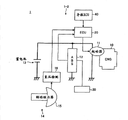
图2是表示根据第一种实施方式的车辆的重要部分的简略结构图。Fig. 2 is a schematic configuration diagram showing essential parts of a vehicle according to the first embodiment.
图3是进行第一种实施方式的车辆控制的情况下的时间图。FIG. 3 is a time chart when vehicle control of the first embodiment is performed.
图4是表示根据第二种实施方式的车辆的重要部分的简略结构图。Fig. 4 is a schematic configuration diagram showing essential parts of a vehicle according to a second embodiment.
图5是进行第二种实施方式的车辆控制的情况下的时间图。FIG. 5 is a time chart when vehicle control of the second embodiment is performed.
具体实施方式 Detailed ways
下面,参照附图详细说明根据本发明的车辆控制系统的一种实施方式。另外,本发明并不由该实施方式限定。另外,在下面的实施方式中的结构部件包含本领域人员可以容易地设想的部件或者实质上相同的部件。Hereinafter, an embodiment of the vehicle control system according to the present invention will be described in detail with reference to the drawings. In addition, this invention is not limited by this embodiment. In addition, structural components in the following embodiments include components that can be easily assumed by those skilled in the art, or components that are substantially the same.
(第一种实施方式)(first implementation)
参照图1至3,对于第一种实施方式进行说明。本实施方式涉及自动地使发动机起动的车辆控制系统。图1是表示根据本发明的第一种实施方式的车辆控制系统的动作的时间图,图2是表示根据本实施方式的车辆的重要部分的简略结构图。Referring to Figures 1 to 3, the first embodiment will be described. This embodiment relates to a vehicle control system that automatically starts an engine. FIG. 1 is a timing chart showing the operation of a vehicle control system according to a first embodiment of the present invention, and FIG. 2 is a schematic configuration diagram showing important parts of a vehicle according to this embodiment.
根据本实施方式的车辆(参照图2的标号1),能够在停车中以及在行驶中停止发动机,以便改善耗油率。车辆1包括利用发动机的负压的制动助力器。在利用发动机负压的制动助力器中,在发动机的停止中,若多次踩下制动踏板,则制动助力器的负压会降低。在这种情况下,虽然通过发动机被自动起动,确保了负压,但是,在为了发动机起动而刚刚将起动器通电之后,由于其突入电流,会变成蓄电池电压降低的状态。According to the vehicle (refer to
另一方面,在车辆1上搭载有ABS装置,由于紧急制动等,轮胎会被锁死的情况下,可以借助ABS装置防止锁死。这里,在ABS装置是消耗来自于蓄电池的电力使制动器动作的装置的情况下,希望ABS装置的动作和由发动机起动引起的蓄电池的电压降低不会重叠。在空转行驶中,或者在停止之前的减速中,在发动机停止的车辆中,存在在车速不是0时发动机也会停止的情况,所以,存在着发动机的自动起动和ABS装置的动作重叠的可能性。On the other hand, if the ABS device is mounted on the
本实施方式的车辆控制系统,在ABS装置动作期间,禁止发动机的起动。车辆控制系统,在由ABS装置进行的制动动作结束(由ABS装置进行的制动器油压的控制结束)的时刻,使发动机自动起动。从而,根据本实施方式的车辆控制系统,ABS装置的动作和由发动机的起动引起的蓄电池的电压降低的重叠受到抑制。通过抑制蓄电池电压降低过大,可以抑制蓄电池的恶化。The vehicle control system of the present embodiment prohibits the start of the engine while the ABS device is operating. The vehicle control system automatically starts the engine when the braking operation by the ABS device ends (the brake oil pressure control by the ABS device ends). Therefore, according to the vehicle control system of the present embodiment, the overlap between the operation of the ABS device and the voltage drop of the battery due to the starting of the engine is suppressed. By suppressing an excessive drop in the battery voltage, deterioration of the battery can be suppressed.
本实施方式以配备有下面的(1)至(6)的结构部件的车辆为前提。The present embodiment is premised on a vehicle equipped with the following structural components (1) to (6).
(1)能够在行驶中将发动机停止并惯性行驶的传动系统。(1) A transmission system capable of stopping the engine and coasting while driving.
(2)制动系统(制动助力器,助力器负压检测装置)。(2) Brake system (brake booster, booster negative pressure detection device).
(3)起动器马达。(3) Starter motor.
(4)ABS。(4) ABS.
(5)蓄电池。(5) Battery.
(6)ECU。(6)ECU.
在图2中,标号1表示车辆。车辆1包括:作为动力源的发动机10、ABS装置12、蓄电池13、制动助力器14及制动器30。In FIG. 2,
发动机10是公知的热机,例如内燃机。发动机10具有起动器11。起动器11是消耗来自于蓄电池13的电力使发动机10起动的起动装置,起动器11例如是公知的起动器马达,通过借助来自于蓄电池13的电力进行旋转,使发动机10旋转。
蓄电池13是能够进行充电放电的蓄电装置。作为蓄电池13,例如,可以采用铅蓄电池。蓄电池13能够向起动器11及ABS装置12供应电力。另外,蓄电池13可以利用由发动机10的图中未示出的交流发电机发电的电力进行充电。The
ABS装置12是辅助驾驶员的制动操作的辅助装置。在车辆1的图中未示出的各个车轮上配置有制动器30。制动器30是借助被供应的油压来产生制动力、对车辆1制动的制动装置。制动器30是借助制动力使车辆1的行驶状态变化的行驶用装置。作为制动器30,例如,可以采用盘式制动器,所述盘式制动器通过借助被供应的油压向制动盘推压制动块,产生制动力。ABS装置12通过消耗来自于蓄电池13的电力使制动器30动作,支援驾驶员的操作(运转操作)。The
在车辆1上设置有作为制动器30的操作构件的图中未示出的制动踏板。ABS装置12辅助驾驶员对制动踏板进行的操作,使制动器30动作。ABS装置12在制动时检测各个车轮的车轮速度,通过控制供应给制动器30的制动油压,防止车辆的锁死。ABS装置12包括图中未示出的控制器、油压泵及电磁阀。ABS装置12的控制器基于检测出的车轮速度使电磁阀动作,调节从油压泵供应给制动器30的制动器油压。A brake pedal (not shown) is provided on the
制动助力器14是制动器30的增力装置。制动助力器14利用发动机10的负压辅助对制动踏板的踏力。制动助力器14的负压室15与发动机10的图中未示出的进气通路连接。在发动机10运转时,进气通路变成负压,该负压被导入负压室15。当驾驶员踩下制动踏板时,借助负压室15的负压与大气压的压力差,增大踏力,传递给主油缸。当通过制动操作使制动助力器14动作时,在制动助力器14中负压被消耗,从发动机10的进气通路向负压室15供应负压。在车辆1上设置有检测负压室15的负压的负压传感器16。The
在车辆1上设置有控制包含发动机10在内的车辆1的各个部分的电子控制单元(ECU)20。ECU20与发动机10电连接,进行发动机10的各种控制。例如,ECU20控制发动机10中的燃料的喷射量、喷射时间、点火时间等。另外,ECU20进行发动机10的起动控制。在起动发动机10的情况下,ECU20使起动器11动作,进行发动机10的起动,当通过起动使得发动机转速上升时,进行向发动机10的燃料的喷射及点火。ECU20进行包括这样的发动机10的控制在内的车辆1的总的控制。本实施方式的车辆控制系统1-1包括发动机10、起动器11、蓄电池13、ABS装置12及ECU20。An electronic control unit (ECU) 20 that controls various parts of the
ECU20使发动机10停止,消除发动机的阻力损失(或者发动机制动损失),可以进行利用惯性使车辆1行驶的惯性行驶。例如,在车辆1的行驶中不加速的情况下进行惯性行驶。ECU20若根据检测对图中未示出的加速踏板的操作量的传感器的检测结果判定为不加速,则进行惯性行驶。在车辆1上,在发动机10与车辆1的图中未示出的驱动轮之间设置有离合器。在该离合器被配合的状态下,发动机10和驱动轮连接,可以传递动力。另外,在离合器断开的状态下,发动机10与驱动轮被切断,不能传递动力。ECU20在惯性行驶时将发动机10与驱动轮之间的离合器断开,使发动机10的旋转停止,并使车辆1行驶。The
这样,由于在惯性行驶时发动机10停止,所以,每次进行制动操作,则负压降低(减少)。由于在于发动机停止状态下进行制动减速的情况下,不能利用发动机10的进气负压,所以,当踩下制动踏板时,制动助力器负压降低,特别是,在多次踩下制动踏板(ポンピングブレ-キ,pumping brake:液压制动)的情况下,制动助力器负压大幅度降低。As described above, since the
ECU20为了保持由制动助力器14产生的辅助功能,自动地使发动机10起动,确保负压。ECU20当负压室15的负压降低到预定的阈值Pt时,由起动器11再次起动发动机10,使负压增大。为了制动助力器14实现该功能,根据必要的负压范围设定该阈值Pt。例如,根据制动助力器14能够恰当地发挥增力功能的负压的下限,设定阈值Pt。当负压室15的负压降低到阈值Pt时,通过发动机10起动且负压增加,制动助力器14能够总是恰当地起着作为增力装置的作用。这样,在进行惯性行驶时,ECU20根据作为与发动机10相关的物理量的负压室15的负压,自动地使发动机10起动。The
由于发动机10起动用的起动器电流是大电流,所以,在发动机起动时,蓄电池电压大幅度降低。这里,伴随着负压降低的发动机10的再起动及ABS装置12的动作均是通过制动踏板的踩下操作而发生的,因此,具有引起两者重叠的可能性。例如,在ABS装置12动作期间,当负压室15的负压降低、进行发动机10的起动时,在ABS装置12的动作中,产生蓄电池13的电压降低。这样,希望抑制ABS装置12的动作与发动机起动引起的蓄电池电压的降低的重叠。Since the starter current for starting the
本实施方式的车辆控制系统1-1,如下面说明的那样,与发动机起动相比,ABS装置12的动作优先。在ABS装置12的动作中,禁止发动机10的自动起动,使发动机10的起动延迟至由ABS装置12引起的制动器30的动作结束。这样,ECU20,在ABS装置12使制动器30动作的期间,通过禁止由起动器11进行的发动机10的起动,抑制ABS装置12的动作与由发动机起动引起的蓄电池13的电压降低的重叠。In the vehicle control system 1 - 1 of the present embodiment, as will be described below, the operation of the
参照图1及图3,对本实施方式的动作进行说明。图3是表示进行本实施方式的车辆控制的情况下的时间图的一个例子的图示。在图3中,(a)表示作为制动助力器14的负压室15的负压的制动助力器负压,(b)表示蓄电池13的输出电压。如图3所示,若制动踏板被踩下,则制动助力器的负压降低,当制动踏板被释放时,与制动踏板被踩下时相比,制动助力器的负压降低得更大。The operation of this embodiment will be described with reference to FIGS. 1 and 3 . FIG. 3 is a diagram showing an example of a time chart when the vehicle control of the present embodiment is performed. In FIG. 3 , (a) shows brake booster negative pressure which is the negative pressure of
参照图1,首先,在步骤S10,利用ECU20,判定作为负压室15的负压的制动助力器负压是否不足发动机自动起动判定值。所谓发动机自动起动判定值,是判定是否自动地起动发动机10的负压的阈值Pt。ECU20根据利用负压传感器16检测出来的负压室15的负压与预定的阈值Pt的比较结果,进行步骤S10的判定。在图3中,在时刻t1,成为制动助力器负压在阈值Pt以下、在步骤S10中进行肯定判定的状态。在步骤S10的判定结果是判定为制动助力器负压不足发动机自动起动判定值的情况下(步骤S10-Y),进入步骤S20,在不是这样的情况下(步骤S10-N),直到变成肯定判定为止,重复步骤S10的判定。Referring to FIG. 1 , first, in step S10 , the
在步骤S20,利用ECU20判定ABS装置12是否处于动作中。ECU20借助与检测ABS装置12的控制器的通信,检测ABS装置12是否处于动作中,在图3中,在时刻t1,制动踏板被踩下,ABS装置12开始动作,ABS装置12持续动作直到在时刻t2制动踏板变成关闭(被释放)为止。借此,从时刻t1到时刻t2,在步骤S20中做出肯定判定。在ABS装置12的动作中,不进入下一个步骤S30(发动机自动起动)而重复步骤S20的判定,借此,禁止发动机10的起动。在步骤S20的判定结果为判定ABS装置12处于动作中的情况下(步骤S20-Y),重复步骤S20的判定,直到做出否定判定(ABS装置12的动作结束)为止,在不被判定为ABS装置12处于动作中的情况(步骤S20-N)下,进入步骤S30。In step S20, the
在步骤S30,借助ECU20进行发动机10的自动起动。由于由ABS装置12进行的制动器30的动作结束,所以,ECU20解除发动机10的起动禁止,使起动器11动作,使发动机10运转,起动发动机10。在图3中,在时刻t2,ABS装置12的动作结束,发动机10被起动。当通过发动机10起动,负压室15的制动助力器负压增加(步骤S40)时,本控制流程结束。In step S30, the automatic start of the
这样,在本实施方式的车辆控制系统1-1中,在ABS装置12动作(步骤S20-Y)期间,不进行发动机10的起动,当ABS装置12的动作结束(步骤S20-N)时,发动机10被起动。借此,抑制ABS装置12的动作与因发动机10的起动引起的蓄电池13的电压降低的重叠。在ABS装置12的动作中,当进行发动机10的起动时,如图3中标号A所示,蓄电池电压的降低与ABS装置12的动作会重叠。与此相对,在本实施方式的车辆控制系统1-1中,如箭头Y1所示,通过将发动机10的起动正时延迟到ABS装置12的动作结束,抑制蓄电池电压的降低和ABS装置12的动作的重叠。另外,当ABS装置12的动作结束时,发动机10被起动、发动机10运转,借此,负压增加(恢复),因而,在直到下一次进行制动操作之前的期间,可以迅速地使制动助力器负压恢复。Thus, in the vehicle control system 1-1 of the present embodiment, the
另外,在本实施方式中,比发动机10的起动优先的辅助装置是ABS装置12,但是,并不局限于此。作为辅助装置,例如,也可以使在迅速地踩下制动踏板的情况下、通过利用促动器产生强制动力的制动器辅助装置或通过制动控制等缓和车轮的横向滑动的VSC(VehicleStability Control:车辆稳定性控制)装置的动作比发动机10的起动优先。例如,在VSC装置动作时,即使制动踏板被踩下、负压室15的负压降低到不足阈值Pt,只要在VSC装置的动作中,禁止发动机10的起动,在VSC装置的动作结束之后起动发动机10即可。即,作为消耗蓄电池13的电力使制动器30动作的辅助装置,也可以将除ABS装置12之外的装置作为比发动机10的起动优先的辅助装置。辅助装置也可以并不局限于在制动踏板被踩下时动作。In addition, in the present embodiment, the assist device that takes priority over the start of the
另外,使辅助装置动作的行驶用装置并不局限于制动器30。也可以是使除制动器30之外的行驶用装置动作的辅助装置比发动机10的起动优先。In addition, the traveling device that activates the assist device is not limited to the
(第一种实施方式的变形例)(Modification of the first embodiment)
在上述第一种实施方式中,在作为辅助装置的ABS装置12已经处于动作中的情况下,发动机10的起动被禁止,但是,此外,在前方存在有被预测为辅助装置动作的行驶环境的情况下,即使在辅助装置使行驶用装置动作之前,也可以禁止发动机10的起动。当以辅助装置是ABS装置12的情况作为例子进行说明时,所谓前方存在有被预测为ABS装置12动作的行驶环境,例如,指的是预测到在前方存在拐角、进行制动操作,并且预测到前方的路面是潮湿的或者是冻结的,ABS装置12进行动作的情况。这些行驶环境可以利用自动导航系统等公知的装置获得。In the above-mentioned first embodiment, when the
在前方存在有被预测为辅助装置动作的行驶环境的情况下,通过在辅助装置使行驶用装置动作之前预先禁止发动机10的起动,抑制发动机10的起动和辅助装置的动作的重叠。When there is a running environment ahead in which the auxiliary device is predicted to operate, starting of the
(第二种实施方式)(Second implementation mode)
下面,参照图4及图5对第二种实施方式进行说明。对于第二种实施方式,对和在上述实施方式中说明的结构部件具有同样的功能的结构部件,赋予相同的标号,省略其重复说明。Next, a second embodiment will be described with reference to FIGS. 4 and 5 . In the second embodiment, components having the same functions as those described in the above-mentioned embodiment are assigned the same reference numerals, and repeated description thereof will be omitted.
本实施方式的车辆控制系统1-2与上述第一种实施方式的车辆控制系统1-1的不同点在于,为了ABS装置12的动作与发动机10的起动不重叠,在预测到ABS装置12的动作的情况下,在ABS装置12动作之前预先使发动机10起动。即,上述第一种实施方式中,在ABS装置12的动作之后使发动机10起动,但是,在实施方式中,在ABS装置12的动作之前使发动机10起动。图4是表示根据本实施方式的车辆的重要部分的概略结构图,图5表示进行本实施方式的车辆控制的情况的时间图的一个例子。The difference between the vehicle control system 1 - 2 of the present embodiment and the vehicle control system 1 - 1 of the above-mentioned first embodiment is that, in order not to overlap the operation of the
如图4所示,在车辆1上设置有导航ECU40。导航ECU40是图中未示出的导航系统的控制装置。作为导航系统,可以使用具有检测本车辆的当前位置的本车位置检测装置、地图数据库的公知的系统。优选地,导航系统可以通过与其它车辆的车车间通信等,从外部取得道路信息。ECU20可以与导航ECU40连接,根据来自于导航ECU40的信号,取得与本车辆位置、前方的道路有关的行驶环境等。As shown in FIG. 4 , a navigation ECU 40 is installed in the
如参照图5说明的那样,本实施方式的车辆控制系统1-2,在预测到进行制动踏板操作、ABS装置12动作的情况下,并且,当预测到由于对应于被预测到的操作的制动助力器负压的降低,做出发动机10的起动要求时,在进行制动操作之前(ABS装置12动作之前),使发动机10起动。As described with reference to FIG. 5 , the vehicle control system 1 - 2 of the present embodiment predicts that the brake pedal is operated and the
在图5中,(a)表示制动助力器负压,(b)表示蓄电池13的输出电压。标号100表示进行本实施方式的控制的情况下的制动助力器负压的推移。另外,符号101表示现有的制动助力器负压的推移的一个例子。符号Pt1及符号Pt2分别表示与制动助力器负压相关的阈值。In FIG. 5 , (a) shows the brake booster negative pressure, and (b) shows the output voltage of the
第二阈值Pt2是和上述第一种实施方式的阈值Pt(参照图3)同样的阈值,当制动助力器负压降低到不足第二阈值Pt2时,根据制动助力器负压,做出发动机10的起动要求。另外,第一阈值Pt1是基于第二阈值Pt2及负压变化量ΔP来决定的。负压变化量ΔP表示,在制动操作开始时,在制动踏板被踩下之后直到制动踏板被释放、制动操作结束为止的一次制动操作中的制动助力器负压的减少量(大小)。The second threshold Pt2 is the same threshold as the threshold Pt (see FIG. 3 ) of the above-mentioned first embodiment. When the negative pressure of the brake booster falls below the second threshold Pt2, according to the negative pressure of the brake booster, a A start request of the
第一阈值Pt1是比第二阈值Pt2大的负压,第一阈值Pt1与第二阈值Pt2之差成为负压变化量ΔP。从而,在当前的负压室15的负压是第一阈值Pt1与第二阈值Pt2之间的负压的情况下,在下一次进行制动操作时,制动操作结束后的制动助力器负压变得小于第二阈值Pt2,可以预测(推定)为有必要起动发动机10。在本实施方式中,在制动助力器负压不足第一阈值Pt1、并且在第二阈值Pt2以上的情况下,当预测为进行制动操作、ABS装置12动作时,在ABS装置12动作之前,发动机10被起动。即,ECU20,除行驶环境之外,还根据作为因制动操作而数值发生变化的物理量的制动助力器负压,决定是否使发动机10起动。The first threshold Pt1 is a negative pressure greater than the second threshold Pt2, and the difference between the first threshold Pt1 and the second threshold Pt2 becomes the negative pressure change amount ΔP. Therefore, when the current negative pressure of the
负压变化量ΔP是预定的值。实际上,由驾驶员进行制动操作的情况下的制动助力器负压的减少量根据制动操作量等而变化。负压变化量ΔP,例如,可以是在一次制动操作中的制动助力器负压的减少量的最大值。在这样设定负压变化量ΔP的情况下,只要在预测为有一点由于下一次制动操作而使制动助力器负压低于第二阈值Pt2的可能性的情况下,就总是使发动机10起动。其结果是,制动助力器负压降低到不足第二阈值Pt2、做出发动机10的起动要求的机会减少。因此,可以预先抑制发动机10的起动要求和ABS装置12的动作的重叠。The negative pressure change amount ΔP is a predetermined value. Actually, the reduction amount of the brake booster negative pressure when the driver performs the brake operation changes according to the brake operation amount and the like. The negative pressure change amount ΔP, for example, may be the maximum value of the decrease amount of the brake booster negative pressure in one braking operation. When the negative pressure change amount ΔP is set in this way, as long as there is a slight possibility that the brake booster negative pressure will be lower than the second threshold value Pt2 due to the next brake operation, the negative pressure is always used. The
这样,在预测为当下一次进行制动操作、制动助力器负压降低时做出发动机10的起动要求的情况下,ECU20在进行制动操作之前使发动机10起动。在惯性行驶过程中,ECU20根据从导航ECU40取得的前方的行驶环境,判定是否进行制动操作。具体地说,ECU20判定本车辆的前方是否存在被预测为进行制动操作的行驶环境,例如,弯道、交叉点、道口、信号等有必要减速或停车的行驶环境。另外,ECU20取得从导航ECU40取得的作为前方的行驶环境的路面信息。路面信息例如是有关路面是否是潮湿的或者路面是否是冻结的等路面状态的信息。在潮湿的路面或冻结的路面等路面μ小的道路上,在进行制动操作的情况下,可以推定为ABS装置12容易动作。即,路面μ小的道路是被预测为ABS装置12动作的行驶环境。In this way, when it is predicted that the start of the
另外,代替路面信息,ECU20也可以根据通过车车间通信取得的信息,预测ABS装置12等辅助装置的动作。例如,在通过与前面行驶的车辆的通信,取得表示在前方道路上行驶的前面行驶的车辆中ABS装置等辅助装置动作的信息的情况下,可以预测为本车辆在该道路上行驶时辅助装置动作。In addition, instead of road surface information, the
在制动助力器负压是第一阈值Pt1与第二阈值Pt2之间的负压的情况下,在根据所取得的行驶环境,在前方存在有预测为进行制动操作的行驶环境以及预测为ABS装置12动作的行驶环境的情况下,ECU20在ABS装置12动作之前使发动机10起动。在图5中,在时刻t3以前的制动助力器负压是在第一阈值Pt1与第二阈值Pt2之间的负压。在不根据制动操作的预测进行发动机的起动的现有技术的控制中,在时刻t4,制动操作开始,在制动助力器负压101低于第二阈值Pt2的时刻,做出发动机10的起动要求。这时,若ABS装置12正在动作,则ABS装置12的动作与发动机10的起动重叠。When the brake booster negative pressure is a negative pressure between the first threshold value Pt1 and the second threshold value Pt2, based on the obtained running environment, there is a running environment predicted to perform a brake operation ahead and a predicted In the case of a running environment in which the
与此相对,在本实施方式的车辆控制系统1-2中,当根据行驶环境预测到ABS装置12的动作时,发动机10被起动。在时刻t3,根据来自于导航ECU40的信息,检测出在前方存在预测为进行制动操作、ABS装置12动作的行驶环境。借此,ECU20在时刻t3借助起动器11使发动机10起动。其结果是,在进行本实施方式的控制的情况下的制动助力器负压100从时刻t3起增加,在开始制动操作的时刻t4,成为足够大的负压。从而,即使进行制动操作,也不产生发动机10的起动要求,因而,ABS装置12的动作与发动机10的起动要求的重叠受到抑制。In contrast, in the vehicle control system 1 - 2 of the present embodiment, the
另外,在本实施方式中,在制动助力器负压在第一阈值Pt1以上的情况下,即使预测到ABS装置12的动作,发动机10也不被起动。即,在被预测为进行制动操作的行驶环境下,在预测为即使实际上进行了制动操作制动助力器负压也不足第二阈值Pt2(做出发动机10的起动要求的值)的情况下,ECU20不使发动机10起动。借此,可以在限定于预见到通过使发动机10起动产生的效果的情况下,在ABS装置12的动作之前使发动机10起动。In addition, in the present embodiment, when the brake booster negative pressure is equal to or greater than the first threshold value Pt1, the
在根据ABS装置12的动作预测使发动机10起动的情况下,为了能够在由驾驶员进行制动操作之前结束发动机10的起动,优选地,ECU20检测出至少在比在要求发动机10起动的时刻到达的地点更靠前方的行驶环境。即,在高车速行驶的情况下,与低车速行驶的情况相比,根据前方的行驶环境进行制动操作的预测、ABS装置12的动作预测即可。In the case of starting the
另外,在本实施方式中,在前方同时存在有预测为进行制动操作的行驶环境以及预测为ABS装置12动作的行驶环境的情况下,发动机10被起动,但是,并不局限于此。例如,也可以在前方存在有预测为进行制动操作的行驶环境、或者预测为在进行了制动操作的场合ABS装置12动作的行驶环境中的至少一种行驶环境的情况下,在ABS装置12动作之前发动机10被起动。Also, in the present embodiment, the
这样,在前方存在有预测为进行制动操作的行驶环境、或者预测为ABS装置12动作的行驶环境中的至少一种行驶环境的情况下,在ABS装置12动作之前发动机10被起动时,即使是比第二阈值Pt2大的制动助力器负压,发动机10也被起动。另一方面,当前方不存在有预测为进行制动操作的行驶环境以及预测为ABS装置12动作的行驶环境中的任何一种行驶环境的情况下,在制动助力器负压成为不足第二阈值Pt2之后,发动机10被起动。即,在前方存在有预测为进行制动操作的行驶环境、或者预测为ABS装置12动作的行驶环境中的至少一种行驶环境的情况下,在比在前方不存在任何一种所述的行驶环境的情况大的制动助力器负压下做出发动机10的起动要求。In this way, when there is at least one of the running environment in which the brake operation is predicted to be performed or the running environment in which the
在辅助装置是在不进行制动操作的情况下也进行动作的装置的情况下,优选地,根据预测为路面信息等辅助装置动作的行驶环境,发动机10被起动。例如,优选地,在不管有没有制动操作,VSC装置都能够动作的情况下,在前方检测出潮湿路面或冻结道路等VSC装置的动作可能性高的行驶环境的情况下,不管是否制动操作被预测到,都作出发动机10的起动要求。When the assist device operates even when the brake is not operated, it is preferable to start the
(第二种实施方式的第一变形例)(First modified example of the second embodiment)
也可以根据制动操作以外的操作、例如根据是否预测为进行转向操作来预测ABS装置12等辅助装置动作的可能性。也可以借助制动操作之外的操作,例如,借助转向操作,推定出车辆稳定性降低、辅助装置动作的可能性增高。在前方存在有可以推定为进行这种车辆稳定性降低的操作的行驶环境的情况下,如果使发动机10起动,则能够更可靠地抑制辅助装置的动作与发动机10的起动的重叠。The possibility of an auxiliary device such as the
对于ABS装置12等辅助装置动作的可能性,不仅根据行驶环境、也可以根据车速等进行预测。另外,也可以根据驾驶员的技能或行驶工况等进行辅助装置的动作预测。例如,在驾驶员的技能低的情况下,或者,是以大的加减速度控制车速的驾驶员的情况下,与驾驶员的技能高的情况或以小的加减速度控制车速的驾驶员的情况相比,对于相同的行驶环境,估计辅助装置动作的可能性会增高。The possibility of an auxiliary device such as the
(第二种实施方式的第二个变形例)(Second modified example of the second embodiment)
在本实施方式中,将负压变化量ΔP作为一次制动操作中的制动助力器负压的减少量的最大值,但是,并不局限于此。负压变化量ΔP也可以根据一次制动操作中的制动助力器负压的减少量范围进行设定。例如,负压变化量ΔP也可以是制动助力器负压的减少量范围的中间值或者最小值。由于负压变化量ΔP越是变成在制动助力器负压的减少量的范围中的小的值,在制动操作之前发动机10被起动的机会越小,所以,从改善耗油率的观点出发,是有利的。另外,负压变化量ΔP也可以根据行驶环境或驾驶员的技能或行驶工况等改变。In the present embodiment, the negative pressure change amount ΔP is set as the maximum value of the decrease amount of the brake booster negative pressure in one brake operation, but the present invention is not limited thereto. The amount of negative pressure change ΔP can also be set according to the range of the decrease amount of the brake booster negative pressure in one braking operation. For example, the negative pressure change amount ΔP may be the middle value or the minimum value of the decrease range of the brake booster negative pressure. Since the negative pressure change amount ΔP becomes a smaller value in the range of the decrease amount of the brake booster negative pressure, the
例如,在负压变化量ΔP可以根据行驶环境而改变的情况下,根据前方的行驶环境,推定制动操作量(行程)。例如,在根据前方的拐角预测为进行制动操作的情况下,根据该拐角的曲率或当前的车速、到达拐角的距离等,推定制动操作量。由推定的制动操作量,推定由于进入拐角时的制动操作而产生的制动助力器负压的减少量,对应于所推定的减少量,决定负压变化量ΔP。在所推定的减少量小的情况下,负压变化量ΔP成为小的值,在所推定的减少量大的情况下,负压变化量ΔP成为大的值。如果这样根据行驶环境决定负压变化量ΔP的话,能够高精度地判定是否由于制动操作而使制动助力器负压变得不足第二阈值Pt2。For example, in a case where the negative pressure change amount ΔP can be changed according to the running environment, the brake operation amount (stroke) is estimated based on the ahead running environment. For example, when a brake operation is predicted based on a corner ahead, the brake operation amount is estimated based on the curvature of the corner, the current vehicle speed, the distance to the corner, and the like. From the estimated brake operation amount, the decrease amount of the brake booster negative pressure due to the brake operation when entering the corner is estimated, and the negative pressure change amount ΔP is determined corresponding to the estimated decrease amount. When the estimated decrease amount is small, the negative pressure change amount ΔP takes a small value, and when the estimated decrease amount is large, the negative pressure change amount ΔP takes a large value. If the negative pressure change amount ΔP is determined according to the running environment in this way, it can be determined with high accuracy whether or not the brake booster negative pressure has become less than the second threshold value Pt2 due to the brake operation.
工业上的利用可能性Industrial Utilization Possibility
如上所述,根据本发明的车辆控制系统,在能够自动地使发动机起动的车辆中是有用的,特别是,适合于抑制辅助装置的动作与发动机的起动重叠。As described above, the vehicle control system according to the present invention is useful in a vehicle capable of automatically starting the engine, and is particularly suitable for preventing the operation of the auxiliary device from overlapping with the starting of the engine.
符号说明Symbol Description
1-1、1-2 车辆控制系统1-1, 1-2 Vehicle Control System
1 车辆1 vehicle
10 发动机10 engine
11 起动器11 starter
12 ABS装置12 ABS device
13 蓄电池13 battery
14 制动助力器14 brake booster
15 负压室15 negative pressure chamber
16 负压传感器16 negative pressure sensor
20 ECU20 ECUs
30 制动器30 brake
40 导航ECU40 Navigation ECU
Pt 阈值Pt Threshold
Pt1 第一阈值Pt1 first threshold
Pt2 第二阈值Pt2 second threshold
ΔP 负压变化量ΔP Negative pressure variation
Claims (9)
Applications Claiming Priority (1)
| Application Number | Priority Date | Filing Date | Title |
|---|---|---|---|
| PCT/JP2010/057712 WO2011135725A1 (en) | 2010-04-30 | 2010-04-30 | Vehicle control system |
Publications (2)
| Publication Number | Publication Date |
|---|---|
| CN102308067A CN102308067A (en) | 2012-01-04 |
| CN102308067B true CN102308067B (en) | 2014-04-02 |
Family
ID=44858935
Family Applications (1)
| Application Number | Title | Priority Date | Filing Date |
|---|---|---|---|
| CN201080002444.9A Expired - Fee Related CN102308067B (en) | 2010-04-30 | 2010-04-30 | Vehicle control system |
Country Status (5)
| Country | Link |
|---|---|
| US (1) | US8880318B2 (en) |
| JP (1) | JP5045815B2 (en) |
| CN (1) | CN102308067B (en) |
| DE (1) | DE112010005534B4 (en) |
| WO (1) | WO2011135725A1 (en) |
Families Citing this family (24)
| Publication number | Priority date | Publication date | Assignee | Title |
|---|---|---|---|---|
| US8996255B2 (en) | 2005-10-13 | 2015-03-31 | Trw Vehicle Safety Systems Inc. | Method and apparatus for providing a safing function in a restraining system |
| US8862355B2 (en) * | 2011-06-22 | 2014-10-14 | Ford Global Technologies, Llc | Method and system for engine control |
| JP5765157B2 (en) * | 2011-09-15 | 2015-08-19 | スズキ株式会社 | Brake control device for vehicle |
| JP5870660B2 (en) * | 2011-12-06 | 2016-03-01 | 日産自動車株式会社 | Vehicle engine automatic control device |
| EP2808520A4 (en) * | 2012-01-23 | 2016-04-20 | Toyota Motor Co Ltd | THERMAL MOTOR RESTART CONTROL DEVICE, VEHICLE AND VEHICLE CONTROL METHOD |
| JP5938941B2 (en) * | 2012-02-24 | 2016-06-22 | 株式会社アドヴィックス | Vehicle control device |
| JP5880294B2 (en) * | 2012-06-05 | 2016-03-08 | 株式会社デンソー | Engine stop / start control device |
| JP6107824B2 (en) | 2012-08-08 | 2017-04-05 | トヨタ自動車株式会社 | Vehicle travel control device |
| JP5741551B2 (en) * | 2012-10-24 | 2015-07-01 | トヨタ自動車株式会社 | Vehicle travel control device |
| US9409576B2 (en) | 2012-10-31 | 2016-08-09 | Toyota Jidosha Kabushiki Kaisha | Vehicle travel controller |
| WO2014068719A1 (en) * | 2012-10-31 | 2014-05-08 | トヨタ自動車株式会社 | Vehicle travel controller |
| CN104768818B (en) * | 2012-10-31 | 2017-04-05 | 丰田自动车株式会社 | The travel controlling system of vehicle |
| JP5900640B2 (en) * | 2012-10-31 | 2016-04-06 | トヨタ自動車株式会社 | Vehicle travel control device |
| DE102012222507B4 (en) * | 2012-12-07 | 2025-01-02 | Vitesco Technologies GmbH | Method for operating a recuperation brake of a motor vehicle and recuperation brake |
| JP2014139034A (en) * | 2013-01-21 | 2014-07-31 | Hitachi Automotive Systems Ltd | Vehicle electric assistor control device |
| JP5741602B2 (en) * | 2013-01-28 | 2015-07-01 | トヨタ自動車株式会社 | Driving support system and driving support method |
| JP2017031806A (en) * | 2013-12-11 | 2017-02-09 | 日産自動車株式会社 | Engine automatic stop control device |
| JP2015221584A (en) * | 2014-05-22 | 2015-12-10 | ダイハツ工業株式会社 | Vehicle control device |
| US10024251B2 (en) * | 2015-06-18 | 2018-07-17 | Ford Global Technologies, Llc | Method for crankcase ventilation in a boosted engine |
| WO2017002228A1 (en) * | 2015-07-01 | 2017-01-05 | 日産自動車株式会社 | Vehicle control device and vehicle control method |
| WO2018029769A1 (en) * | 2016-08-09 | 2018-02-15 | 日産自動車株式会社 | Vehicle control method and vehicle control device |
| JP6639378B2 (en) * | 2016-12-15 | 2020-02-05 | 本田技研工業株式会社 | Vehicle control system |
| US10683836B2 (en) * | 2018-07-30 | 2020-06-16 | Ford Global Technologies, Llc | Methods and systems for controlling automatic engine starting |
| JP6994007B2 (en) * | 2019-07-01 | 2022-02-03 | 本田技研工業株式会社 | Vehicle control device |
Citations (5)
| Publication number | Priority date | Publication date | Assignee | Title |
|---|---|---|---|---|
| JP2000310133A (en) * | 1999-04-26 | 2000-11-07 | Toyota Motor Corp | Engine automatic stop and start device |
| JP2002213269A (en) * | 2000-11-15 | 2002-07-31 | Toyota Motor Corp | Car |
| JP2006322361A (en) * | 2005-05-18 | 2006-11-30 | Fujitsu Ten Ltd | Device and method for automatic stopping and starting engine and engine control system |
| CN101045454A (en) * | 2006-03-20 | 2007-10-03 | 三菱扶桑卡客车株式会社 | Control device for a hybrid electric vehicle |
| CN101535617A (en) * | 2006-11-21 | 2009-09-16 | 五十铃自动车株式会社 | Automatic starter/stopper of engine |
Family Cites Families (49)
| Publication number | Priority date | Publication date | Assignee | Title |
|---|---|---|---|---|
| US3225704A (en) | 1961-12-18 | 1965-12-28 | Alden Self Transit Syst | Transportation systems |
| US3254608A (en) | 1965-03-29 | 1966-06-07 | Alden Self Transit Syst | Vehicles and transportation systems |
| US3532060A (en) | 1966-12-29 | 1970-10-06 | Alden Self Transit Syst | Transportation system and vehicle |
| JPS5835245A (en) * | 1981-08-25 | 1983-03-01 | Toyota Motor Corp | Automatically stopping and restarting device of engine |
| USRE32474E (en) * | 1982-06-07 | 1987-08-11 | Variable time delay apparatus for controlling the start of a vehicle | |
| JPH112143A (en) | 1997-06-11 | 1999-01-06 | Aqueous Res:Kk | Vehicle control device |
| DE19911736B4 (en) | 1998-03-17 | 2005-12-15 | Honda Giken Kogyo K.K. | Machine stop control system for a vehicle |
| JP3706733B2 (en) | 1998-03-17 | 2005-10-19 | 本田技研工業株式会社 | Vehicle engine stop control device |
| DE69919648T2 (en) | 1998-09-28 | 2005-09-08 | Toyota Jidosha K.K., Toyota | Start-stop device for motor vehicle engine |
| JP2001065675A (en) * | 1999-08-26 | 2001-03-16 | Honda Motor Co Ltd | Vehicle control device |
| JP3675281B2 (en) * | 2000-02-15 | 2005-07-27 | 日産自動車株式会社 | Automatic engine stop / restart device for vehicle |
| JP2001227375A (en) | 2000-02-17 | 2001-08-24 | Mitsubishi Electric Corp | Idle stop device |
| GB2370130B (en) * | 2000-10-11 | 2004-10-06 | Ford Motor Co | A control system for a hybrid electric vehicle |
| JP2002195137A (en) | 2000-12-27 | 2002-07-10 | Aisin Aw Co Ltd | Hybrid vehicle and control method for the same |
| JP2002216113A (en) | 2001-01-16 | 2002-08-02 | Fujitsu Ten Ltd | Object recognition device |
| US7277782B2 (en) | 2001-01-31 | 2007-10-02 | Oshkosh Truck Corporation | Control system and method for electric vehicle |
| JP3475179B2 (en) | 2001-02-06 | 2003-12-08 | 日野自動車株式会社 | Clutch control device |
| JP2003041967A (en) * | 2001-07-26 | 2003-02-13 | Toyota Motor Corp | Automatic stop control device for internal combustion engine |
| US7293621B2 (en) | 2002-04-10 | 2007-11-13 | Charge-O-Matic Energy Recovery Devices, Llc | Vehicle drive system with energy recovery system and vehicle mounting same |
| US20060213703A1 (en) | 2002-04-10 | 2006-09-28 | Long Thomas W | Vehicle drive system with energy recovery system and vehicle mounting same |
| JP3743421B2 (en) * | 2002-04-23 | 2006-02-08 | 日産自動車株式会社 | Vehicle control device |
| JP3772823B2 (en) | 2002-10-25 | 2006-05-10 | トヨタ自動車株式会社 | Fuel injection amount control device for internal combustion engine |
| DE10307462B4 (en) | 2003-02-21 | 2019-02-28 | Robert Bosch Gmbh | Method for controlling the drive unit of a vehicle |
| US7091629B2 (en) * | 2003-06-24 | 2006-08-15 | Detroit Diesel Corporation | Engine control system and method of automatic starting and stopping a combustion engine |
| JP2005088703A (en) | 2003-09-16 | 2005-04-07 | Honda Motor Co Ltd | Brake force control device for vehicle |
| JP2005178627A (en) | 2003-12-19 | 2005-07-07 | Toyota Motor Corp | Integrated control system for vehicles |
| SE0400605L (en) * | 2004-03-09 | 2005-01-25 | Volvo Lastvagnar Ab | Method, system and computer program for automatic freewheeling of vehicles |
| JP2006037780A (en) * | 2004-07-23 | 2006-02-09 | Toyota Motor Corp | Power output apparatus and control method thereof |
| US20060030450A1 (en) | 2004-08-09 | 2006-02-09 | Kyle Ronald L | Hybrid vehicle formed by converting a conventional IC engine powered vehicle and method of such conversion |
| JP4356598B2 (en) | 2004-12-07 | 2009-11-04 | マツダ株式会社 | Vehicle engine starting device |
| JP4321821B2 (en) | 2005-01-28 | 2009-08-26 | アイシン・エィ・ダブリュ株式会社 | Image recognition apparatus and image recognition method |
| JP2007187090A (en) | 2006-01-13 | 2007-07-26 | Toyota Motor Corp | Speed maintenance control device |
| JP2007255271A (en) | 2006-03-22 | 2007-10-04 | Toyota Motor Corp | Vehicle control device |
| JP4677945B2 (en) | 2006-04-24 | 2011-04-27 | トヨタ自動車株式会社 | Vehicle travel control device |
| JP2008191781A (en) | 2007-02-01 | 2008-08-21 | Hitachi Ltd | Collision avoidance system |
| US20080238189A1 (en) * | 2007-03-27 | 2008-10-02 | Kuo Ching-Chuang G | System and method for vacuum booster assist |
| JP4784563B2 (en) | 2007-06-22 | 2011-10-05 | トヨタ自動車株式会社 | Control device for lock-up clutch |
| DE102007035424A1 (en) | 2007-07-28 | 2009-01-29 | Dr. Ing. H.C. F. Porsche Aktiengesellschaft | Control interface for vehicle, has drive unit, where interface selects sailings of vehicle when output of unit is not introduced, so that vehicle is either propelled or braked when vehicle is brought into mode |
| JP4978603B2 (en) | 2008-09-30 | 2012-07-18 | トヨタ自動車株式会社 | Vehicle control device |
| US8370041B2 (en) * | 2008-10-31 | 2013-02-05 | Ford Global Technologies, Llc | Reduced energy vacuum pump control |
| WO2010058470A1 (en) | 2008-11-20 | 2010-05-27 | トヨタ自動車株式会社 | Controller of power transmission device for vehicle |
| US20100191446A1 (en) * | 2009-01-28 | 2010-07-29 | Gm Global Technology Operations, Inc. | Systems and methods for predictive engine re-starting and predictive neutral/idle operation of a vehicle |
| JP5381160B2 (en) | 2009-02-27 | 2014-01-08 | 日産自動車株式会社 | Vehicle operation assist device and vehicle operation assist method |
| DE102009011281A1 (en) * | 2009-03-02 | 2010-09-09 | Dr.Ing.H.C.F.Porsche Aktiengesellschaft | Method for operating an internal combustion engine |
| US9677530B2 (en) * | 2009-09-21 | 2017-06-13 | Ford Global Technologies, Llc | Assisted direct start engine control for enhanced launch performance |
| JP5552339B2 (en) | 2010-03-12 | 2014-07-16 | トヨタ自動車株式会社 | Vehicle control device |
| CN102892655B (en) | 2010-05-13 | 2015-08-26 | 丰田自动车株式会社 | Controller of vehicle and vehicle control system |
| US8746719B2 (en) | 2010-08-03 | 2014-06-10 | Polaris Industries Inc. | Side-by-side vehicle |
| US8992505B2 (en) | 2011-04-18 | 2015-03-31 | Thorne Consulting & Intellectual Property, LLC | Medical syringe filling and valving |
-
2010
- 2010-04-30 CN CN201080002444.9A patent/CN102308067B/en not_active Expired - Fee Related
- 2010-04-30 JP JP2010545307A patent/JP5045815B2/en not_active Expired - Fee Related
- 2010-04-30 US US13/060,174 patent/US8880318B2/en not_active Expired - Fee Related
- 2010-04-30 WO PCT/JP2010/057712 patent/WO2011135725A1/en not_active Ceased
- 2010-04-30 DE DE112010005534.3T patent/DE112010005534B4/en not_active Expired - Fee Related
Patent Citations (5)
| Publication number | Priority date | Publication date | Assignee | Title |
|---|---|---|---|---|
| JP2000310133A (en) * | 1999-04-26 | 2000-11-07 | Toyota Motor Corp | Engine automatic stop and start device |
| JP2002213269A (en) * | 2000-11-15 | 2002-07-31 | Toyota Motor Corp | Car |
| JP2006322361A (en) * | 2005-05-18 | 2006-11-30 | Fujitsu Ten Ltd | Device and method for automatic stopping and starting engine and engine control system |
| CN101045454A (en) * | 2006-03-20 | 2007-10-03 | 三菱扶桑卡客车株式会社 | Control device for a hybrid electric vehicle |
| CN101535617A (en) * | 2006-11-21 | 2009-09-16 | 五十铃自动车株式会社 | Automatic starter/stopper of engine |
Also Published As
| Publication number | Publication date |
|---|---|
| JPWO2011135725A1 (en) | 2013-07-18 |
| WO2011135725A1 (en) | 2011-11-03 |
| US8880318B2 (en) | 2014-11-04 |
| DE112010005534B4 (en) | 2018-11-29 |
| US20110270501A1 (en) | 2011-11-03 |
| CN102308067A (en) | 2012-01-04 |
| JP5045815B2 (en) | 2012-10-10 |
| DE112010005534T5 (en) | 2013-04-11 |
Similar Documents
| Publication | Publication Date | Title |
|---|---|---|
| CN102308067B (en) | Vehicle control system | |
| JP5477137B2 (en) | Engine automatic stop / restart control system | |
| US9567965B2 (en) | Intelligent idle stop and go control device and method thereof | |
| CN105745133B (en) | Control device for vehicle and the control method for engine | |
| US9126596B2 (en) | Control system for vehicle and control method therefor | |
| US9714621B2 (en) | Automatic engine control apparatus | |
| CN1636806B (en) | Brake system for idle stop vehicle | |
| US20160298559A1 (en) | Engine start control apparatus | |
| WO2008062615A1 (en) | Automatic starter/stopper of engine | |
| CN103228514B (en) | Controller of vehicle and control method for vehicle | |
| CN107683230A (en) | car control unit | |
| JP2011226316A (en) | Vehicle control device | |
| JP5737203B2 (en) | Engine control device | |
| JP5333665B2 (en) | Braking control system | |
| JP5197507B2 (en) | Control device for idle stop car | |
| JP2006321268A (en) | Economic running control method and economic running controlling device | |
| CN103328791B (en) | Engine restart control device, vehicle and vehicle control method | |
| CN104512419B (en) | Method for influencing the creep torque of a car during a stationary state of the car | |
| CN105035070A (en) | Vehicle drive away based engine control | |
| JP2011240850A (en) | Brake control system | |
| CN105793128A (en) | vehicle control device | |
| CN104074613B (en) | Engine control unit | |
| JP6454884B2 (en) | Automatic engine stop control device for vehicle | |
| JP2011247237A (en) | Device for control of idling stop vehicle | |
| JP2012111412A (en) | Vehicle control system |
Legal Events
| Date | Code | Title | Description |
|---|---|---|---|
| C06 | Publication | ||
| PB01 | Publication | ||
| C10 | Entry into substantive examination | ||
| SE01 | Entry into force of request for substantive examination | ||
| C14 | Grant of patent or utility model | ||
| GR01 | Patent grant | ||
| CF01 | Termination of patent right due to non-payment of annual fee |
Granted publication date: 20140402 |
|
| CF01 | Termination of patent right due to non-payment of annual fee |