CN102282428B - Data centre and apparatus and method for data centre cooling - Google Patents
Data centre and apparatus and method for data centre cooling Download PDFInfo
- Publication number
- CN102282428B CN102282428B CN200980148656.5A CN200980148656A CN102282428B CN 102282428 B CN102282428 B CN 102282428B CN 200980148656 A CN200980148656 A CN 200980148656A CN 102282428 B CN102282428 B CN 102282428B
- Authority
- CN
- China
- Prior art keywords
- air
- data center
- bypass flow
- cold
- cooling
- Prior art date
- Legal status (The legal status is an assumption and is not a legal conclusion. Google has not performed a legal analysis and makes no representation as to the accuracy of the status listed.)
- Expired - Fee Related
Links
Images


Classifications
-
- H—ELECTRICITY
- H05—ELECTRIC TECHNIQUES NOT OTHERWISE PROVIDED FOR
- H05K—PRINTED CIRCUITS; CASINGS OR CONSTRUCTIONAL DETAILS OF ELECTRIC APPARATUS; MANUFACTURE OF ASSEMBLAGES OF ELECTRICAL COMPONENTS
- H05K7/00—Constructional details common to different types of electric apparatus
- H05K7/20—Modifications to facilitate cooling, ventilating, or heating
- H05K7/20709—Modifications to facilitate cooling, ventilating, or heating for server racks or cabinets; for data centers, e.g. 19-inch computer racks
- H05K7/20718—Forced ventilation of a gaseous coolant
- H05K7/20745—Forced ventilation of a gaseous coolant within rooms for removing heat from cabinets, e.g. by air conditioning device
-
- F—MECHANICAL ENGINEERING; LIGHTING; HEATING; WEAPONS; BLASTING
- F24—HEATING; RANGES; VENTILATING
- F24F—AIR-CONDITIONING; AIR-HUMIDIFICATION; VENTILATION; USE OF AIR CURRENTS FOR SCREENING
- F24F11/00—Control or safety arrangements
- F24F11/70—Control systems characterised by their outputs; Constructional details thereof
- F24F11/72—Control systems characterised by their outputs; Constructional details thereof for controlling the supply of treated air, e.g. its pressure
-
- F—MECHANICAL ENGINEERING; LIGHTING; HEATING; WEAPONS; BLASTING
- F24—HEATING; RANGES; VENTILATING
- F24F—AIR-CONDITIONING; AIR-HUMIDIFICATION; VENTILATION; USE OF AIR CURRENTS FOR SCREENING
- F24F11/00—Control or safety arrangements
- F24F11/70—Control systems characterised by their outputs; Constructional details thereof
- F24F11/80—Control systems characterised by their outputs; Constructional details thereof for controlling the temperature of the supplied air
- F24F11/81—Control systems characterised by their outputs; Constructional details thereof for controlling the temperature of the supplied air by controlling the air supply to heat-exchangers or bypass channels
-
- H—ELECTRICITY
- H05—ELECTRIC TECHNIQUES NOT OTHERWISE PROVIDED FOR
- H05K—PRINTED CIRCUITS; CASINGS OR CONSTRUCTIONAL DETAILS OF ELECTRIC APPARATUS; MANUFACTURE OF ASSEMBLAGES OF ELECTRICAL COMPONENTS
- H05K7/00—Constructional details common to different types of electric apparatus
- H05K7/20—Modifications to facilitate cooling, ventilating, or heating
- H05K7/20709—Modifications to facilitate cooling, ventilating, or heating for server racks or cabinets; for data centers, e.g. 19-inch computer racks
-
- F—MECHANICAL ENGINEERING; LIGHTING; HEATING; WEAPONS; BLASTING
- F24—HEATING; RANGES; VENTILATING
- F24F—AIR-CONDITIONING; AIR-HUMIDIFICATION; VENTILATION; USE OF AIR CURRENTS FOR SCREENING
- F24F11/00—Control or safety arrangements
- F24F11/30—Control or safety arrangements for purposes related to the operation of the system, e.g. for safety or monitoring
-
- F—MECHANICAL ENGINEERING; LIGHTING; HEATING; WEAPONS; BLASTING
- F24—HEATING; RANGES; VENTILATING
- F24F—AIR-CONDITIONING; AIR-HUMIDIFICATION; VENTILATION; USE OF AIR CURRENTS FOR SCREENING
- F24F11/00—Control or safety arrangements
- F24F11/70—Control systems characterised by their outputs; Constructional details thereof
- F24F11/72—Control systems characterised by their outputs; Constructional details thereof for controlling the supply of treated air, e.g. its pressure
- F24F11/74—Control systems characterised by their outputs; Constructional details thereof for controlling the supply of treated air, e.g. its pressure for controlling air flow rate or air velocity
- F24F11/75—Control systems characterised by their outputs; Constructional details thereof for controlling the supply of treated air, e.g. its pressure for controlling air flow rate or air velocity for maintaining constant air flow rate or air velocity
-
- F—MECHANICAL ENGINEERING; LIGHTING; HEATING; WEAPONS; BLASTING
- F24—HEATING; RANGES; VENTILATING
- F24F—AIR-CONDITIONING; AIR-HUMIDIFICATION; VENTILATION; USE OF AIR CURRENTS FOR SCREENING
- F24F2110/00—Control inputs relating to air properties
-
- H—ELECTRICITY
- H05—ELECTRIC TECHNIQUES NOT OTHERWISE PROVIDED FOR
- H05K—PRINTED CIRCUITS; CASINGS OR CONSTRUCTIONAL DETAILS OF ELECTRIC APPARATUS; MANUFACTURE OF ASSEMBLAGES OF ELECTRICAL COMPONENTS
- H05K7/00—Constructional details common to different types of electric apparatus
- H05K7/20—Modifications to facilitate cooling, ventilating, or heating
- H05K7/20709—Modifications to facilitate cooling, ventilating, or heating for server racks or cabinets; for data centers, e.g. 19-inch computer racks
- H05K7/20836—Thermal management, e.g. server temperature control
Landscapes
- Engineering & Computer Science (AREA)
- General Engineering & Computer Science (AREA)
- Chemical & Material Sciences (AREA)
- Combustion & Propulsion (AREA)
- Mechanical Engineering (AREA)
- Physics & Mathematics (AREA)
- Computer Hardware Design (AREA)
- Thermal Sciences (AREA)
- Microelectronics & Electronic Packaging (AREA)
- Fluid Mechanics (AREA)
- Life Sciences & Earth Sciences (AREA)
- Atmospheric Sciences (AREA)
- Cooling Or The Like Of Electrical Apparatus (AREA)
- Air Conditioning Control Device (AREA)
Abstract
Description
背景技术 Background technique
数据中心是计算设施位于其中的环境。通常,数据中心容纳被布置在固定件(例如机柜或者机架)中的多个计算机。每一个计算机可以包括组件的组合,所述组件例如一个或者多个处理器和相关联的存储器装置、例如磁基或者光基存储装置的存储装置,和一个或者多个通信装置。 A data center is an environment in which computing facilities are located. Typically, data centers house multiple computers arranged in fixtures such as cabinets or racks. Each computer may include a combination of components such as one or more processors and associated memory devices, storage devices such as magnetic- or optical-based storage devices, and one or more communication devices.
由于在数据中心中计算设施的集中,需要进行冷却从而将数据中心内的温度维持到可接受的水平。通常,布置一个或者多个计算机室空调(CRAC)单元以从数据中心接收暖空气并且向其供应冷却空气。每一个CRAC单元包括一个或者多个风扇以将数据中心空气抽入CRAC单元中。例如通过暴露于包括冷水的热交换器,当抽入空气通过CRAC单元时,该抽入空气被冷却,并且被排入数据中心的冷区域中以冷却计算设施。计算设施的每一个部件通常包括风扇以抽吸空气从中通过从而冷却在计算设施内的电子组件和/或装置。空气被从计算设施排入数据中心的热区域中从而返回该一个或者多个CRAC单元。 Due to the concentration of computing facilities in a data center, cooling is required to maintain the temperature within the data center to an acceptable level. Typically, one or more computer room air conditioning (CRAC) units are arranged to receive warm air from the data center and supply cool air thereto. Each CRAC unit includes one or more fans to draw data center air into the CRAC unit. The intake air is cooled as it passes through the CRAC units, such as by exposure to a heat exchanger including cold water, and is exhausted into a cold area of the data center to cool the computing facility. Each component of a computing facility typically includes a fan to draw air therethrough to cool electronic components and/or devices within the computing facility. Air is exhausted from the computing facility into the hot zone of the data center to return to the one or more CRAC units.
图1示意在具有1、2或者3个操作CRAC单元的数据中心内的和在计算设施的一个和二十四个部件(每一个均具有内部风扇)之间的空气压力相对于气流的曲线图。101代表关于单一CRAC单元的气流和压力;线102代表关于并行操作的两个CRAC单元的气流和压力;并且线103代表并行操作的三个CRAC单元。关于计算设施的一个部件的气流和压力由线104代表,而关于计算设施的、被并行布置的二十四个部件的压力和气流由线105示出。在图1中示出通过计算设施的、中间数目的部件的气流,但是为了清楚起见,每一条线未被单独标注。将会注意,仅仅作为示例描述了计算设施的二十四个部件,并且数据中心可以包括计算设施的另外的部件。
Figure 1 illustrates a graph of air pressure versus airflow within a data center with 1, 2, or 3 operating CRAC units and between one and twenty-four components of a computing facility (each with internal fans) . 101 represents airflow and pressure for a single CRAC unit;
在控制通过每一个CRAC单元的气流时存在操作差异106。在图1(a)中示出在控制通过三个CRAC单元的气流时的差异并且在图1(b)中示出CRAC单元操作差异对计算设施的二十四个部件的影响107,图1(b)代表在图1(a)中的相同部分的特写。由于与计算设施的每一个部件的较低操作压力相比CRAC单元的相对较高操作空气压力,CRAC单元空气压力的相对较小变化对于冷却系统和计算设施的冷却具有相对较大的影响。对于计算设施而言,这是麻烦的,特别地因为计算设施的很多复杂部件(例如服务器等)包括大大地受到CRAC单元气流输出的变化所影响的多个温度传感器和复杂的冷却控制系统。
There are
本发明的实施例的目的在于至少减轻现有技术的一个或者多个问题。 Embodiments of the present invention aim at at least alleviating one or more problems of the prior art.
附图说明 Description of drawings
现在将参考附图,仅仅通过示例描述本发明的实施例,其中: Embodiments of the invention will now be described, by way of example only, with reference to the accompanying drawings, in which:
图1示出对于若干不同的CRAC和计算设施的部件的、压力相对于气流的图示; Figure 1 shows a graph of pressure versus airflow for several different CRACs and components of a computing facility;
图2示出在数据中心中的、未隔离的冷和热空气流中的气流的示意图示; Figure 2 shows a schematic illustration of airflow in unisolated cold and hot airflows in a data center;
图3示出根据本发明的一个实施例的数据中心的示意图示; Figure 3 shows a schematic illustration of a data center according to one embodiment of the present invention;
图4示出根据本发明的另一个实施例的数据中心的截面和平面视图; Figure 4 shows a cross-sectional and plan view of a data center according to another embodiment of the present invention;
图5示出根据本发明的进一步的实施例的数据中心的截面和平面视图; Figure 5 shows a cross-sectional and plan view of a data center according to a further embodiment of the present invention;
图6示出根据本发明的再进一步的实施例的数据中心的截面和平面视图; Figure 6 shows a cross-sectional and plan view of a data center according to yet a further embodiment of the present invention;
图7示意结合CRAC单元之间的冗余的、根据本发明的实施例的数据中心冷却系统; 7 illustrates a data center cooling system according to an embodiment of the invention incorporating redundancy between CRAC units;
图8示意结合CRAC单元之间的冗余的、根据本发明的进一步的实施例的数据中心冷却系统; Figure 8 illustrates a data center cooling system according to a further embodiment of the present invention incorporating redundancy between CRAC units;
图9示意结合CRAC单元之间的冗余的、根据本发明的另一个实施例的数据中心冷却系统; 9 illustrates a data center cooling system according to another embodiment of the present invention incorporating redundancy between CRAC units;
图10示意结合CRAC单元之间的冗余的、根据本发明的进一步的实施例的数据中心;并且 Figure 10 illustrates a data center according to a further embodiment of the invention incorporating redundancy between CRAC units; and
图11示意对于本发明的实施例的设计约束。 Figure 11 illustrates design constraints for an embodiment of the invention.
具体实施方式 Detailed ways
为了更好地理解本发明的实施例,首先将参考图2描述在现有技术的、未隔离的数据中心200中的气流。应该理解“未隔离”是指数据中心200由单一体积形成,计算设施位于该单一体积中并且从一个或者多个CRAC单元向该单一体积供应冷却空气。
In order to better understand embodiments of the present invention, the airflow in a prior art, non-isolated
数据中心200包括CRAC单元201和计算设施202,CRAC单元201被布置成向数据中心200供应冷却空气210,通过将数据中心200内的空气抽入计算设施的外壳中并且排回到数据中心200中来冷却计算设施202。
The
在图2中指示了各种气流,并且现在将连同示例温度一起描述这些气流以示意在数据中心200内的空气的运动。CRAC单元201在15°C的示例温度下向数据中心200供应冷却空气。所供应的空气210可以与负压力气流220混合。当靠近CRAC单元排放口存在负压力区时引起负压力气流220,在CRAC单元排放口处,被排放的空气的速度是高的并且速度压力超过数据中心中的总空气压力,因此导致负压力区。可以在地板回风口、地板开口等周围存在这种负压力区。将会注意并非所有的数据中心都包括负压力区。仅仅当围绕CRAC气流排放口存在负压力时才创建负压力气流,并且已知的设计技术试图减小在这些区中存在的负压力。在所示意的示例中,负压力气流220处于25°C的示例温度并且用于将所得到的组合气流230的温度升高到16°C。
Various airflows are indicated in FIG. 2 and will now be described along with example temperatures to illustrate the movement of air within
在计算设施202的附近存在旁通(bypass)气流240。旁通气流240是与任何负压力气流220混合的、来自CRAC单元的输出的冷却空气,其绕开计算设施202并且通常返回CRAC单元201,而不向计算设施202提供冷却。
A
在损失了一些流向旁通气流240的冷却空气之后,剩余空气250通过计算设施202并且被计算设施202加热到35°C的示例温度。从计算设施排出的空气与旁通气流240混合以形成被返回CRAC201单元以用于冷却的、具有25°C的示例温度的合成气流260。
After losing some cooling air to bypass
如果计算设施202与由气流250供应的相比抽入更多的空气,则再循环气流270得以形成。再循环气流270是再循环以再次进入计算设施202的、来自计算设施202的暖空气。在该示例中,再循环气流270处于35°C的温度。根据再循环气流270与供应气流230的比率,流入计算设施202中的所得组合气流250处于24°C的示例温度。
If
现在将参考示意性地示出数据中心300的图3描述本发明的一个实施例。
An embodiment of the invention will now be described with reference to FIG. 3 which schematically shows a
在本发明的实施例中,在冷和热空气区域之间的隔离被用于控制其间的气流。通过适当构造气密性屏障(例如壁、门、计算机柜等)实现了在冷和热空气区域之间的隔离。特别地,在本发明的实施例中,通过隔离而防止或者至少基本上最小化再循环气流。负压力气流可以存在于数据中心200中。然而,已知的设计技术可以被用于最小化负压力气流并且因此将不对此进一步讨论。在本发明的实施例中,预定水平的旁通气流在数据中心中得以维持。在本发明的实施例中,旁通气流被测量并且响应于测量的旁通气流控制一个或者多个CRAC单元的输出气流,从而旁通气流被维持在预定水平。在本发明的一些实施例中,该预定水平是旁通气流的最小水平,旁通气流被维持在所述最小水平下或者接近所述最小水平。然而,在本发明的其它实施例中,旁通气流被维持在预定的范围内。
In an embodiment of the invention, isolation between the cold and hot air zones is used to control the airflow therebetween. Separation between cold and hot air areas is achieved by properly constructing airtight barriers (eg walls, doors, computer cabinets, etc.). In particular, in embodiments of the invention, recirculation airflow is prevented, or at least substantially minimized, by isolation. Negative pressure airflow may exist in
有利地,通过维持通常恒定但是相对较小水平的旁通气流,在计算设施的空气进口处维持了小的正压力,而与计算设施的操作负荷无关。以此方式,被供应到计算设施的空气与离开供应该空气的一个或者多个CRAC单元的空气相同,即空气的再循环得以最小化或者消除,并且仅仅供应冷却计算设施和维持小水平的旁通气流所必要的量的空气。此外,减少了与串联的CRAC单元风扇和计算设施风扇相关的问题。 Advantageously, by maintaining a generally constant but relatively small level of bypass airflow, a small positive pressure is maintained at the computing facility's air inlet regardless of the computing facility's operating load. In this way, the air supplied to the computing facility is the same as the air leaving the one or more CRAC units that supplied it, i.e., recirculation of air is minimized or eliminated, and only cooling of the computing facility is supplied and a small level of bypass is maintained. The amount of air necessary to ventilate the flow. Additionally, problems associated with cascading CRAC unit fans and computing facility fans are reduced.
将参考数据中心的冷和热部分描述本发明的实施例。应该理解冷部分与热部分隔离并且包含从一个或者多个空调单元供应的、比较凉的空气,而热部分包含从计算设施排出的暖空气。 Embodiments of the invention will be described with reference to cold and hot sections of a data center. It should be understood that the cold section is isolated from the hot section and contains cooler air supplied from one or more air conditioning units, while the hot section contains warm air exhausted from the computing facility.
参考图3,数据中心300包括CRAC单元310、计算设施320、流量计330和控制单元340。
Referring to FIG. 3 ,
CRAC单元310包括冷却单元311,冷却单元311被布置成冷却正被风扇312移动通过CRAC单元的空气。冷却单元311可以是热交换器,所述热交换器使得例如水的冷却液体通过其一个通道而同时空气通过另一个通道,从而该液体从空气吸收热量,以由此从CRAC单元310输出冷却气流315。从CRAC单元310发出的冷却空气315被排入数据中心300的冷部分350中。通过屏障370将冷部分350与数据中心300的热部分360隔离。在计算设施320的外壳内的一个或者多个风扇(未示出)从冷部分350将空气抽吸通过计算设施320。被计算设施320加热的空气被从计算设施320排入数据中心300的热部分360中。
The
流量计330位于隔离数据中心300的冷和热部分350、360的屏障370的孔隙中。流量计330位于数据中心300的去耦区域中。去耦区域是数据中心300中的在CRAC单元310和计算设施320内存在的风扇之间的公共区域。理想地,去耦区域尽实际可能地大从而实现气流的有效去耦。然而,在实际的实施例中,去耦区域具有有限的尺寸以实现充分的去耦。允许从冷部分350到热部分360的旁通气流380流动通过流量计330,从而流量计330测量旁通气流380的速度。指示测量的速度的旁通气流信号331被流量计330输出到控制单元340。虽然将会认识到可以使用能够测量气流速率的任何装置,但是在一些实施例中流量计330是形成通过在冷和热部分之间的隔离部的孔隙的流栅(flow grid)。也就是说,在冷和热部分之间的旁通气流流动通过流栅。流栅由被歧管连接的一组平行的管子形成。管子是有孔的并且提供与通过流栅的空气流速度的平方成比例的单一差分压力信号331。流栅是通过测量跨流栅的平均压降而确定流速的多点平均装置。在一些实施例中,该流栅可以是Wilson流栅。在可替代实施例中,可以使用旋转流量计测量旁通气流速率。
The
旁通气流信号331被提供给控制单元340,控制单元340响应于旁通气流信号331控制CRAC单元310的气流速率。在所描述的实施例中,控制单元340被布置成输出CRAC单元控制信号341来控制风扇312的速度以将旁通气流380维持在预定水平。也就是说,根据通过流量计330的旁通气流380的速度调节风扇312的速度。风扇312的速度可以被控制从而旁通气流380被维持在例如在总CRAC单元310输出气流315的1和5%之间。有利地,当风扇312的速度降低时,CRAC单元将消耗较少的能量。在可替代实施例中,控制信号341被提供给机械致动器,该机械致动器被布置成控制在冷和热部分之间的隔离部中的孔隙的截面面积,从而可以响应于控制信号341而通过增加或者降低孔隙的截面面积来控制旁通气流速率。
The
虽然已经与图3相结合地将控制单元340描述为单独的实体,但是在其它实施例中控制单元340可以形成CRAC单元310的部分。在这些实施例中,CRAC单元310和位于其中的控制单元340被布置成接收旁通气流信号331并且响应于此控制CRAC单元310的输出。此外,虽然控制信号341被示为控制单一CRAC单元310,但是控制信号341可以控制多个CRAC单元。
Although the
有利地,通过数据中心300的冷和热部分350、360的隔离部370防止或者至少最小化低效的再循环气流,并且通过旁通气流380的确定以及响应于此由控制单元340控制CRAC单元310的输出,来管理通过计算设施320的、从CRAC单元310输出的气流。
Advantageously, inefficient recirculation airflow is prevented or at least minimized by the
现在将参考图4描述本发明的进一步的实施例。图4所示实施例可以被称作在其中包含冷空气的冷空气包含数据中心,而大多数的数据中心是被热空气填充的。 A further embodiment of the invention will now be described with reference to FIG. 4 . The embodiment shown in Figure 4 may be referred to as a cold air containing data center in which cold air is contained, whereas most data centers are filled with hot air.
图4(a)示出通过包括如将描述的地板下和高架管道或者送气管(plenum)的数据中心400的竖直截面。图4(b)示出从存在于数据中心400内的计算机柜上方获取的、数据中心400的平面视图。 Figure 4(a) shows a vertical section through a data center 400 including underfloor and overhead ducts or plenums as will be described. FIG. 4( b ) shows a plan view of the data center 400 taken from above the computer cabinets present within the data center 400 .
数据中心400包括容纳计算设施的多个机架或者机柜410、420、430、440。在计算设施被安装在机架中的情形中,则适当地使用挡板和/或刷子来隔离数据中心400的冷和热部分。在所描述的实施例中,计算设施被安装在四个机柜410、420、430、440中,从而数据中心400被以交替的方式划分成冷451、452和热461、462、463过道。将会认识到,可以在数据中心400中包括其它数目的机柜410、420、430、440。由一个或者多个CRAC单元(未示出)输出的冷空气通过地板下冷空气送气管或者管道450而被供应到第一和第二冷过道451、452。冷过道451、452由包括壁和/或门的、在计算机柜410、420、430、440的每一个端部处的隔离部形成。进入冷过道451、452的空气的大部分被抽吸通过计算设施机柜410、420、430、440以冷却在其中安装的计算设施。在机柜410、420、430、440中的计算设施内存在的风扇通过每一个机柜410、420、430、440的前部中的进口并且通过计算设施外壳而从冷过道451、452抽吸空气以冷却内部组件和装置。空气通过在每一个机柜的后部中的出口而被从机柜410、420、430、440排入形成数据中心400的热部分460的部分的热过道461、462、463中。如在图4(a)和(b)中所示,数据中心400的热部分460存在于机柜410、420、430、440的上方和周围。在存在于在数据中心400的每一个冷过道451、452和热部分460之间的隔离部中的孔隙中布置流栅480、490,以允许旁通气流从中通过。如在前所讨论的那样,旁通气流是从冷部分450进入热部分460而没有冷却计算设施的冷空气。 The data center 400 includes a plurality of racks or cabinets 410, 420, 430, 440 housing computing facilities. Where the computing facilities are mounted in racks, then baffles and/or brushes are used as appropriate to isolate the hot and cold parts of the data center 400 . In the depicted embodiment, the computing facilities are installed in four racks 410, 420, 430, 440 such that the data center 400 is divided into cold 451, 452 and hot 461, 462, 463 aisles in an alternating fashion. It will be appreciated that other numbers of racks 410 , 420 , 430 , 440 may be included in data center 400 . Cool air output by one or more CRAC units (not shown) is supplied to first and second cool aisles 451 , 452 through an underfloor cool air duct or duct 450 . Cold aisles 451 , 452 are formed by partitions at each end of computing cabinets 410 , 420 , 430 , 440 including walls and/or doors. A substantial portion of the air entering the cold aisles 451, 452 is drawn through the computing facility racks 410, 420, 430, 440 to cool the computing facilities installed therein. The fans present within the computing facility in the cabinets 410, 420, 430, 440 draw air from the cold aisles 451, 452 through inlets in the front of each cabinet 410, 420, 430, 440 and through the computing facility enclosure to Cool internal components and devices. Air is exhausted from the cabinets 410 , 420 , 430 , 440 through outlets in the rear of each cabinet into hot aisles 461 , 462 , 463 forming part of the hot section 460 of the data center 400 . As shown in FIGS. 4( a ) and ( b ), a hot portion 460 of the data center 400 exists above and around the cabinets 410 , 420 , 430 , 440 . Flow grids 480, 490 are arranged in apertures present in the insulation between each of the cold aisles 451, 452 and the hot section 460 of the data center 400 to allow bypass airflow therethrough. As previously discussed, bypass airflow is cold air entering hot section 460 from cold section 450 without cooling the computing facility.
图4(a)示出流栅的两种不同的布置。在左手冷却过道451中,流栅480被大致水平地布置在冷过道451隔离部的顶板中,而在右手冷过道452中,流量计490被大致竖直地布置在从机柜490向上延伸的隔离壁中。空气沿着位于热部分460之上的返回空气送气管470被从空气部分460返回(一个或者多个)CRAC单元以进行冷却。空气通过多个孔隙进入返回空气送气管470。 Figure 4(a) shows two different arrangements of flow grids. In the left-hand cooling aisle 451, the flow grid 480 is arranged approximately horizontally in the ceiling of the partition of the cold aisle 451, while in the right-hand cold aisle 452, the flow meter 490 is arranged approximately vertically in the partition extending upward from the cabinet 490. in the wall. Air is returned from the air section 460 to the CRAC unit(s) along return air duct 470 located above the hot section 460 for cooling. Air enters the return air supply tube 470 through a plurality of apertures.
在图4所示数据中心400中,来自一个或者多个CRAC单元的单一空气供给被提供给多个冷过道451、452并且流栅480、490中的每一个均输出旁通气流信号。如上所述地,虽然在图4中未示出,但是控制单元被布置成接收由流栅480、490输出的多个旁通气流信号并且检测所测量的旁通气流中的一个或者多个气流何时降至低于预定的旁通流水平。作为响应,控制单元被布置成控制该一个或者多个CRAC单元以增加到多个冷过道451、452的冷却空气的气流速率。可替代地,通过冷部分450的划分,可以由专用CRAC单元向每一个冷过道451、452供应冷却空气,从而每一个冷过道从相应的CRAC单元接收冷却空气。在这种布置中,用于每一个冷过道451、452的流栅被布置成向控制单元输出旁通气流信号以根据来自那里的旁通气流控制流入冷过道中的气流。这些布置中的任一种均可以被应用于在这里描述的数据中心的实施例。 In the data center 400 shown in Figure 4, a single air supply from one or more CRAC units is provided to multiple cold aisles 451, 452 and each of the flow grilles 480, 490 outputs a bypass airflow signal. As mentioned above, although not shown in Figure 4, the control unit is arranged to receive a plurality of bypass airflow signals output by the flow grids 480, 490 and to detect one or more of the measured bypass airflows When to drop below a predetermined bypass flow level. In response, the control unit is arranged to control the one or more CRAC units to increase the flow rate of cooling air to the plurality of cold aisles 451 , 452 . Alternatively, by partitioning the cold section 450, each cold aisle 451, 452 may be supplied with cooling air by a dedicated CRAC unit, whereby each cold aisle receives cooling air from a corresponding CRAC unit. In this arrangement, the flow grids for each cold aisle 451, 452 are arranged to output a bypass airflow signal to the control unit to control the airflow into the cold aisle according to the bypass airflow therefrom. Any of these arrangements may be applied to the data center embodiments described herein.
现在将参考图5描述本发明的进一步的实施例。如在图4中那样,图5(a)示出通过数据中心500的截面视图并且图5(b)示出平面视图。图5所示数据中心500可以被称作在其中包含从计算设施排出的热空气的热空气包含数据中心,而大多数的数据中心包含冷空气。
A further embodiment of the invention will now be described with reference to FIG. 5 . As in FIG. 4 , FIG. 5( a ) shows a cross-sectional view through the
如在图4中那样,计算设施被布置在四个计算机柜510、520、530、540中并且来自一个或者多个CRAC单元(未示出)的冷却空气经由冷送气管550被供应以进入在成对计算机柜510、520和530、540之间的冷过道551、552。空气被在计算机柜510、520、530、540内容纳的计算设施内存在的风扇抽入每一个计算机柜510、520、530、540的前部并且通过每一个机柜的后部而被排入多个热过道561、562、563中。然而,与图4所示实施例相对照,在图5中的热过道561、562、563被在成对的机柜510、520和530、540之间并且从所述成对的机柜向上的、竖直延伸的隔离部所包含。在成对的计算机柜510、520、530、540之间的每一个热过道561、562、563的端部被壁、门或其组合封住。图5(b)示出具有门553的一个热过道562的端部,门553允许通向热过道562。热过道隔离部向上延伸以朝向热送气管560中的孔隙导引热空气,从而将空气返回该一个或者多个CRAC单元。每一个热过道561、562、563包括被布置于数据中心500的冷和热部分450、460之间的隔离部的孔隙中的流栅570、580、590。流栅570、580、590可以被布置在形成隔离部的壁中以形成热过道的门或者其部分,或者布置在任何其它适当的位置,从而可以测量在冷部分450和热部分460之间的旁通气流并且响应于此输出旁通气流信号以控制一个或者多个CRAC单元,如上所述。
As in FIG. 4 , computing facilities are arranged in four
图6示出根据本发明的一个实施例的数据中心600的进一步的实施例。如在图4和5中那样,图6(a)示出通过数据中心600的截面视图并且图6(b)示出平面视图。图6所示数据中心600可以被称作机柜排气口包含数据中心,因为包含每一个计算机柜的排气口并且该排气口被导向成将热空气返回顶板返回送气管或者管道。 Figure 6 shows a further embodiment of a data center 600 according to an embodiment of the present invention. As in Figures 4 and 5, Figure 6(a) shows a cross-sectional view through the data center 600 and Figure 6(b) shows a plan view. The data center 600 shown in FIG. 6 may be referred to as a rack exhaust containment data center because the exhaust of each computing cabinet is contained and directed to return hot air to the ceiling and return to the plenum or duct.
参考图6,该数据中心包括在其中容纳计算设施的四个计算机柜610、620、630、640。冷送气管650供应来自一个或者多个CRAC单元(未示出)的冷却空气,冷却空气被进给到在计算机柜610、620、630、640之间的冷过道651、652、653、654、655中。在计算设施中操作的风扇通过进口将空气从冷过道抽入机柜610、620、630、640中。经由向上延伸的排气口包含装置,热空气然后被直接地排放到热空气返回送气管660中。每一个冷过道651、652、653、654、655包括流栅670、680、690、695,所述流栅被布置于在该冷过道和热送气管660之间的隔离部的孔隙中,以允许被相应的流栅670、680、690、695测量的、在其间的旁通气流。在图6所示实施例中,流栅670、680、690、695被布置成允许旁通气流直接地从冷过道651、652、653、654、655进入热送气管660。
Referring to FIG. 6, the data center includes four
现在将参考以下附图描述本发明的实施例,所述实施例结合CRAC单元冗余,由此即使当一个或者多个CRAC单元具有有限的操作(例如不可操作)时,也可以充分地实现数据中心冷却。在这些实施例中,多个流栅测量在一定区域例如冷过道中的旁通气流,每一个流栅均被布置成输出相应的旁通气流信号。多个旁通气流信号由被布置成控制一个或者多个CRAC单元的控制单元接收。在CRAC单元具有降低的操作的情形中,输出旁通气流信号以控制其它CRAC单元的流栅测量降低的旁通气流水平。作为响应,其它CRAC单元增加气流以补偿具有降低的操作的CRAC单元。 Embodiments of the present invention will now be described with reference to the following figures, which incorporate CRAC unit redundancy whereby data Cool in center. In these embodiments, a plurality of flow grilles measure bypass airflow in a certain area, such as a cold aisle, each flow grill being arranged to output a corresponding bypass airflow signal. A plurality of bypass airflow signals are received by a control unit arranged to control one or more CRAC units. In the event that a CRAC unit has reduced operation, a bypass airflow signal is output to control the flow gates of other CRAC units to measure the reduced bypass airflow level. In response, the other CRAC units increase airflow to compensate for the CRAC unit having reduced operation.
参考图7,数据中心700包括在成行的计算机柜之间的多个过道。在所描述的、图7(a)所示的实施例中,类似于在前参考图5所描述的数据中心,数据中心700具有热空气包含布置。数据中心700包括容纳计算机设施的六行机柜711、712、713、714、715、716,但是将会认识到,机柜的数目仅仅是为了示意性的意图。交替的热761、762、763和冷751、752、753、754过道被插入该成行的机柜711、712、713、714、715、716之间。第一热过道761位于第一和第二行机柜711、712之间;第二热过道762位于第三和第四行机柜713、714之间;并且第三热过道763位于第五和第六行机柜715、716之间。热过道761、762、763形成数据中心700的热区域。冷区域750围绕机柜711、712、713、714、715、716和热过道761、762、763。冷区域750包括四个冷过道751、752、753、754并且进一步包括地板下管道(未示出),通过地板下管道,冷却空气被供应到在围绕热过道761、762、763的每一对机柜之间插入的冷过道751、752、753、754。三个CRAC单元721、722、723每一个均被布置成从数据中心700的热区域接收热空气。将会注意,在图7(a)中的CRAC单元721、722、723的位置仅仅是为了示意性的意图并且CRAC单元可以位于数据中心700的内部或者外部。冷空气被CRAC单元721、722、723返回冷部分750,并且然后在被排放到对应的热过道761、762、763之前,被抽入机柜711、712、713、714、715、716中以冷却在其中容纳的计算设施。 Referring to FIG. 7, a data center 700 includes a plurality of aisles between rows of computer racks. In the described embodiment shown in FIG. 7( a ), the data center 700 has a hot air containment arrangement similar to the data center previously described with reference to FIG. 5 . The data center 700 includes six rows of racks 711, 712, 713, 714, 715, 716 housing computer facilities, although it will be appreciated that the number of racks is for illustrative purposes only. Alternating hot 761 , 762 , 763 and cold 751 , 752 , 753 , 754 aisles are inserted between the rows of cabinets 711 , 712 , 713 , 714 , 715 , 716 . The first hot aisle 761 is located between the first and second rows of cabinets 711, 712; the second hot aisle 762 is located between the third and fourth rows of cabinets 713, 714; and the third hot aisle 763 is located between the fifth and sixth rows between row cabinets 715,716. Hot aisles 761 , 762 , 763 form the hot zone of data center 700 . The cold zone 750 surrounds the cabinets 711 , 712 , 713 , 714 , 715 , 716 and the hot aisles 761 , 762 , 763 . The cold zone 750 includes four cold aisles 751 , 752 , 753 , 754 and further includes underfloor ducts (not shown) through which cooling air is supplied to each pair surrounding the hot aisles 761 , 762 , 763 Cold aisles 751, 752, 753, 754 interposed between cabinets. Each of the three CRAC units 721 , 722 , 723 is arranged to receive hot air from the hot zone of the data center 700 . It will be noted that the location of the CRAC units 721 , 722 , 723 in FIG. 7( a ) is for illustrative purposes only and that the CRAC units may be located inside or outside the data center 700 . Cool air is returned to the cold section 750 by the CRAC units 721 , 722 , 723 and then drawn into the cabinets 711 , 712 , 713 , 714 , 715 , 716 for cooling before being discharged into the corresponding hot aisles 761 , 762 , 763 Computing facilities housed within it.
每一个热过道761、762、763包括具有在其中布置以允许旁通气流从包括冷过道751、752、753、754的冷区域750进入热过道761、762、763的流栅731,732、733的孔隙。在先前描述的实施例中,每一个流栅被布置成提供指示通过流栅的旁通气流的单一旁通气流信号。这在图7(b)的左手列中示出,其中,例如,第一暖空气过道761包括提供旁通气流信号以控制第一CRAC单元721的第一流栅731。类似地,第二和第三暖空气过道762、763包括第二和第三流栅732、733,第二和第三流栅732、733被布置成分别测量流入每一个暖空气过道762、763中的旁通气流,并且输出旁通气流信号。然而,在具有CRAC单元冗余的、本发明的实施例中,每一个热过道761、762、763包括具有多个部分的流栅,每一个部分测量从其通过的旁通气流并且提供旁通气流信号以控制对应的一个或者多个CRAC单元。
Each hot aisle 761 , 762 , 763 includes a
参考图7(a)和图7(b)的中间列,在具有N+1冗余的一个实施例中,第一热过道761包括被划分成两个部分的流栅731,每一个部分独立地提供指示从其通过的旁通气流的速度的信号。可替代地,可以在第一热过道761中布置两个单独的流栅。测量流入第一热过道761中的旁通气流的、第一流栅731的第一部分F1向被布置成控制第一CRAC单元721的控制单元(未示出)提供旁通气流信号,而流栅731的第二部分F2向控制单元提供旁通气流信号以控制第二CRAC单元722。类似地,测量流入第三热过道763中的旁通气流的第三流栅733被划分成两个部分F2、F3。第一部分F2向控制单元提供旁通气流信号以控制第二CRAC单元722,而第二部分F3向控制单元提供旁通气流信号以控制第三CRAC单元723。测量流至第二热过道762的旁通气流的第二流栅732被划分成三个部分F1、F2、F3,每一个部分分别地向控制第一、第二和第三CRAC单元721、722、723的控制单元提供指示流入第二热过道762中的旁通气流的信号。
Referring to the middle column of Figures 7(a) and 7(b), in one embodiment with N+1 redundancy, the first hot aisle 761 includes a
在例如第二CRAC单元722发生故障或者具有降低的操作的情形中,降低的旁通气流速度将被第二流栅732的部分F1、F3测量,所述部分向控制单元提供指示流入第二热过道762的旁通气流速度的旁通气流信号。因此,控制单元被布置成增加从第一和第三CRAC单元721、723流入冷部分750中的冷却空气的流速以维持流入第二热过道762中的旁通气流的预定速度。类似地,如果第一CRAC单元721发生故障或者具有降低的操作,则降低的旁通气流被第一流栅731的部分F2测量,所述部分提供旁通气流信号以控制第二CRAC单元722。作为响应,控制单元被布置成控制第二CRAC单元722以增加冷却空气的流速,从而维持流至第一热过道731的旁通气流的预定速度。
In the event, for example, that the second CRAC unit 722 fails or has reduced operation, the reduced bypass airflow velocity will be measured by portions F1, F3 of the
现在将参考图7(b)的右手列描述本发明的、进一步的实施例。在具有N+2冗余的这个实施例中,每一个流栅731、732、733均包括提供旁通气流信号以控制CRAC单元721、722、723中的每一个的部分。也就是说,每一个流栅731、732、733被划分成一定数目的部分F1、F2、F3,该数目等于CRAC单元721、72、722的数目。流栅的每一个部分F1、F2、F3被布置成向控制单元提供旁通气流信号以控制对应的CRAC单元721、722、723。在所描述的实施例中,每一个流栅731、732、733被划分成三个部分F1、F2、F3,每一个部分提供旁通气流信号以控制CRAC单元721、722、723中的对应的一个,但是可以设想其它数目的部分和CRAC单元。在一个或者多个CRAC单元721、722、723发生故障或者具有降低的操作的情形中,则流入一个或者多个热过道761、762、763中的旁通气流速度的、对应的下降被测量流入那些热过道中的旁通气流的流栅部分F1、F2、F3测量,并且控制单元被布置成通过增加来自其余CRAC单元721、722、723的冷却空气的流速而作出响应。因此,一个或者多个CRAC单元的故障或者降低的操作被其余的CRAC单元补偿。
A further embodiment of the invention will now be described with reference to the right hand column of Figure 7(b). In this embodiment with N+2 redundancy, each
参考图7(c),示出流栅的三种配置。流栅可以形成热过道761、762、763的门或者壁。流栅731(a)可以被划分成单一部分以提供单一旁通气流信号。在另一实施例中,如在图7(b)中所示,流栅731(b)可以被水平地划分成第一和第二部分F1、F2,从而每一个部分均提供旁通气流信号。在另一实施例中,流栅731(c)可以被划分成第一、第二和第三部分F1、F2、F3,或者被划分成对应于CRAC单元的数目的、不同数目的部分。还将认识到,可以设想流栅划分的其它布置。 Referring to Figure 7(c), three configurations of the flow grid are shown. The flow grids may form doors or walls of the thermal aisles 761 , 762 , 763 . The flow grid 731(a) can be divided into a single section to provide a single bypass flow signal. In another embodiment, as shown in FIG. 7(b), the flow grid 731(b) may be divided horizontally into first and second sections F1, F2 such that each section provides a bypass flow signal . In another embodiment, the flow grid 731(c) may be divided into first, second and third sections F1, F2, F3, or into a different number of sections corresponding to the number of CRAC units. It will also be appreciated that other arrangements of flow grid divisions are conceivable.
参考示出平面视图和沿着图8(a)所示的线A-A的通过数据中心800的截面的图8(a)和(b),示出如在图7中那样具有N+1(3+1)冗余和热过道包含的、本发明的进一步的实施例。
Referring to Figures 8(a) and (b) showing a plan view and a section through the
数据中心800包括冷部分850,冷部分850包括四个CRAC单元821、822、823、824向其中提供冷却空气的冷过道851、852。在计算机柜811-818中的、相对的成对计算机柜之间形成四个热过道861、862、863、864。在每一个热过道861、862、863、864的端部处,流栅831、832、833、834被布置成测量流入相应的热过道861、862、863、864中的旁通气流。加热空气被从机柜811-818排入热过道861、862、863、864中的对应的一个并且暖空气通过热空气送气管或者管道860而被进给到CRAC单元821、822、823、834。
The
如在图8(b)中所示,每一个流栅831、833被划分成四个部分F1-F4,每一个部分对应于CRAC单元821-824之一。虽然示出仅仅两个流栅831、833,但是其它流栅832、834具有等效的划分。如上参考图7所述,每一个流栅部分F1-F4向控制单元输出指示通过该部分的旁通气流的旁通气流信号以控制CRAC单元821-824中的对应的一个。在CRAC单元821-824中的一个或者多个发生故障或者具有降低的操作的情形中,控制单元被布置成控制其余的CRAC单元以增加冷却空气的流速从而维持流入每一个热过道861-864中的旁通气流的预定水平。
As shown in FIG. 8( b ), each
参考图9(a),示出类似于图6的、具有排气口空气包含布置的数据中心900的布局。数据中心900包括插入成行机柜911、912、913、914、915、916之间的多个冷过道951-955。冷却空气被三个CRAC单元921、922、923供应到冷过道。示出了两种不同的流栅布置。第一布置包括被布置在第一、第三和第五冷过道951、953、955中的三个流栅931、932、933。在图9(b)中示出每一个流栅的划分。在具有N冗余(无冗余)的布置中,流栅931、932、933未被划分并且每一个均输出旁通气流信号以控制相应的CRAC单元931、932、933。在中间列中示出具有N+1冗余的第一流栅布置,其中第一流栅931被划分成提供旁通气流信号以分别地控制第一和第二CRAC单元931、932的两个部分F1、F2。第二流栅932被划分成提供旁通气流信号以分别地控制第一、第二和第三CRAC单元931、932、933的三个部分F1、F2、F3。第三流栅933被划分成提供旁通气流信号以分别地控制第二和第三CRAC单元932、933的两个部分F2、F3。然而,在第二可能的布置中,流栅934、935被布置在第二和第三冷过道952、954中。第二布置的第一流栅934被划分成两个部分F1、F2以提供旁通气流信号从而分别地控制第一和第二CRAC单元921、922。第二布置的第二流栅935被划分成提供旁通气流信号以分别地控制第二和第三CRAC单元922、923的两个部分。具有N+2冗余的流栅布置在图9(b)的右手列中示出并且与在前参考图7描述的相同。
Referring to FIG. 9( a ), there is shown a layout of a
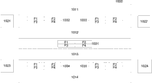
图10示意在具有排气口空气包含的数据中心1000中的流栅的两个另外的示例布置。数据中心1000包括四个CRAC单元1021、1012、1023、1024向其供应冷却空气的四行机柜1011、1012、1013、1014。在第一布置中,被划分成四个部分F1、F2、F3、F4的流栅1031在数据中心中被布置在中心处。流栅1031的每一个部分均提供旁通气流信号以控制CRAC单元1021、1012、1023、1024中的相应的一个。第一部分F1提供旁通气流信号以控制第一CRAC单元1021;第二部分F2提供旁通气流信号以控制第二CRAC单元1022;第三部分F3提供旁通气流信号以控制第三CRAC单元1023;并且第四部分F4提供旁通气流信号以控制第四CRAC单元1024。有利地,这种布置最小化CRAC单元控制系统的复杂度并且仅仅要求在其中定位流栅1031的单一去耦区域。然而,在另一种布置中,四个流栅1032、1033、1034、1035被大致朝向数据中心1000的每一个角部布置。这种布置要求更多的去耦区域,但是提供CRAC单元1021、1022、1023、1024的、更加敏感的控制,因为流栅1032、1033、1034、1035测量在数据中心1000的不同区中的旁通气流。在这种布置中,控制CRAC单元1021、1022、1023、1024中的每一个的控制单元接收指示旁通气流速度的四个旁通气流信号。在四个旁通气流信号之一降至低于预定水平的情形中,适当的控制单元被布置成增加从那个CRAC单元到数据中心1000的冷却空气的流量。
FIG. 10 illustrates two additional example arrangements of flow grills in a
图11示意对于本发明的实施例的设计考虑。图11示意性地示意包括CRAC单元1110、流栅1130、第一服务器1140和第二服务器1150的数据中心1100。第一服务器1140代表在数据中心1100中靠近流栅1130定位的服务器,而第二服务器1150代表在数据中心的、远离流栅1130的区中定位的服务器。
Figure 11 illustrates design considerations for an embodiment of the invention. FIG. 11 schematically illustrates a
由于将旁通气流维持于预定水平,流栅在流栅的远端位于其中的数据中心的冷和热部分之间经历恒定压力差△P。当不同流速的空气被抽吸通过服务器1140以进行冷却时,在全操作负荷和部分操作负荷二者下,第一服务器1140也经历在冷和热部分之间的压力差△P。保证第一服务器1140经历的差分压力△P对于服务器1140的冷却控制系统而言可忍受是重要的。在第一服务器1140和第二服务器1150之间的空气供应和返回路线中,各种压力损失发生,例如在空气供应和返回送气管中、通过空气供应地板回风口、在服务器位于其中的机柜中等。因此,第二服务器1150经历的压力差小于第一服务器1140经历的压力差。如果在服务器1140、1150之间的压力损失超过在第一服务器1140处的压力差△P,则第二服务器1150可以经历在数据中心的冷和热部分之间的负压力,该负压力将试图从热部分将热空气抽吸通过服务器。因此,即使当服务器1140、1150之一或这两者的操作处于最小负荷时,也应该保证第二服务器1150总是经历正压力差△P。
As a result of maintaining the bypass airflow at a predetermined level, the flow grid experiences a constant pressure differential ΔΡ between the cold and hot parts of the data center in which the distal ends of the flow grid are located. When air of different flow rates is drawn through the
有利地,本发明的实施例提供数据中心冷却的准确控制,所述控制响应于数据中心中的计算设施的冷却通过量以最优方式管理CRAC单元的输出。此外,本发明的一些实施例容忍其中一个或者多个CRAC单元具有降低的操作的状况,例如在发生故障的情形中。 Advantageously, embodiments of the present invention provide accurate control of data center cooling that optimally manages the output of CRAC units in response to the cooling throughput of computing facilities in the data center. Furthermore, some embodiments of the invention tolerate conditions in which one or more CRAC units have degraded operation, such as in the event of a failure.
本发明的实施例可以是静态数据中心,例如由永久结构例如建筑物形成的数据中心。然而,本发明的其它实施例可以是可移动数据中心。可移动数据中心可以是其中可以在装运集装箱式结构内容纳计算机设施的集装箱式数据中心。在其它实施例中,可移动数据中心可以是安装轮子的容器,例如货车或者卡车拖车。其它可移动数据中心可以是被安装在船舶(例如船)上或者内的那些数据中心。可移动数据中心还可以被称作便携式按需数据中心。 Embodiments of the invention may be static data centers, such as data centers formed from permanent structures such as buildings. However, other embodiments of the invention may be mobile data centers. A transportable data center may be a containerized data center in which computer facilities may be housed within a shipping container-like structure. In other embodiments, the mobile data center may be a container on wheels, such as a van or truck trailer. Other transportable data centers may be those installed on or within a vessel, such as a ship. A mobile data center may also be referred to as a portable on-demand data center.
在本说明书(包括任何所附权利要求、摘要和附图)中公开的所有的特征和/或如此公开的、任何方法或者过程的所有步骤可以被以任何组合方式组合,除了其中这种特征和/或步骤中的至少一些相互排斥的组合。 All features disclosed in this specification (including any accompanying claims, abstract and drawings) and/or all steps of any method or process so disclosed may be combined in any combination, except where such features and and/or at least some mutually exclusive combinations of the steps.
在本说明书(包括任何所附权利要求、摘要和附图)中公开的每一个特征可以被服务于相同、等价或者类似的意图的可替代特征替代,除非明确地另有规定。因此,除非明确地另有规定,所公开的每一个特征仅仅是等价或者类似特征的一般系列中的一个示例。 Each feature disclosed in this specification (including any accompanying claims, abstract and drawings) may be replaced by alternative features serving the same, equivalent or similar purpose, unless expressly stated otherwise. Thus, unless expressly stated otherwise, each feature disclosed is one example only of a generic series of equivalent or similar features.
本发明不限于前面的任何实施例的细节。本发明扩展至在本说明书(包括任何所附权利要求、摘要和附图)中公开的特征中的任何新颖的特征或任何新颖的组合,或者如此公开的任何方法或者过程的步骤中的任何新颖的步骤,或任何新颖的组合。权利要求不应该被理解成仅仅涵盖前面的实施例,而是还涵盖落入权利要求的范围内的任何实施例。 The invention is not restricted to the details of any foregoing embodiments. The invention extends to any novel feature or any novel combination of features disclosed in this specification (including any accompanying claims, abstract and drawings) or to any novel step in any method or process so disclosed steps, or any novel combination. The claims should not be read to cover only the foregoing embodiments, but also any embodiments that fall within the scope of the claims.
Claims (15)
Applications Claiming Priority (3)
| Application Number | Priority Date | Filing Date | Title |
|---|---|---|---|
| GB0822213.5 | 2008-12-05 | ||
| GB0822213.5A GB2466178B (en) | 2008-12-05 | 2008-12-05 | Data centre and apparatus and method for data centre cooling |
| PCT/EP2009/065171 WO2010063559A1 (en) | 2008-12-05 | 2009-11-13 | Data centre and apparatus and method for data centre cooling |
Publications (2)
| Publication Number | Publication Date |
|---|---|
| CN102282428A CN102282428A (en) | 2011-12-14 |
| CN102282428B true CN102282428B (en) | 2014-01-22 |
Family
ID=40289537
Family Applications (1)
| Application Number | Title | Priority Date | Filing Date |
|---|---|---|---|
| CN200980148656.5A Expired - Fee Related CN102282428B (en) | 2008-12-05 | 2009-11-13 | Data centre and apparatus and method for data centre cooling |
Country Status (8)
| Country | Link |
|---|---|
| US (1) | US8634963B2 (en) |
| EP (1) | EP2352953B1 (en) |
| KR (1) | KR101564480B1 (en) |
| CN (1) | CN102282428B (en) |
| AU (1) | AU2009321637B2 (en) |
| BR (1) | BRPI0916505B1 (en) |
| GB (1) | GB2466178B (en) |
| WO (1) | WO2010063559A1 (en) |
Families Citing this family (18)
| Publication number | Priority date | Publication date | Assignee | Title |
|---|---|---|---|---|
| US9681587B2 (en) | 2007-08-30 | 2017-06-13 | Pce, Inc. | System and method for cooling electronic equipment |
| WO2010002388A1 (en) * | 2008-06-30 | 2010-01-07 | Hewlett-Packard Development Company, L.P. | Cooling medium distribution over a network of passages |
| DE102009011007B4 (en) * | 2009-03-02 | 2011-09-15 | Rittal Gmbh & Co. Kg | Method and device for controlling an air conditioning system for data processing systems |
| GB2467808B (en) | 2009-06-03 | 2011-01-12 | Moduleco Ltd | Data centre |
| US9204578B2 (en) * | 2010-02-09 | 2015-12-01 | It Aire Inc. | Systems and methods for cooling data centers and other electronic equipment |
| GB201008825D0 (en) | 2010-05-26 | 2010-07-14 | Bripco Bvba | Data centre cooling system |
| TW201221042A (en) * | 2010-11-12 | 2012-05-16 | Hon Hai Prec Ind Co Ltd | Noise reduction apparatus, method, and container data center including the same |
| CN102128482B (en) * | 2011-03-30 | 2012-12-26 | 浙江浙大网新能源技术有限公司 | Integrated air-conditioning control system of data center |
| JP5869297B2 (en) * | 2011-11-02 | 2016-02-24 | 株式会社Nttファシリティーズ | Air conditioning system, air conditioning system control program, and air conditioning system control method |
| KR101226196B1 (en) * | 2012-01-16 | 2013-01-28 | 임수빈 | Energy-saving internet data center constructed within disaster proof tunnel |
| WO2013114528A1 (en) * | 2012-01-30 | 2013-08-08 | 富士通株式会社 | Air-conditioning system |
| CN103499961B (en) * | 2013-10-11 | 2017-01-11 | 北京百度网讯科技有限公司 | Cold water automatic control system of data center room |
| JP2015161489A (en) * | 2014-02-28 | 2015-09-07 | 富士通株式会社 | Data center, control program of control device and control method of data center |
| JP2016148574A (en) * | 2015-02-12 | 2016-08-18 | セイコーエプソン株式会社 | Electronic component conveying device and electronic component inspection device |
| US11076509B2 (en) | 2017-01-24 | 2021-07-27 | The Research Foundation for the State University | Control systems and prediction methods for it cooling performance in containment |
| US20210092875A1 (en) | 2017-10-31 | 2021-03-25 | Envion Ag | Mobile data center and method of operating the same |
| RU2692046C2 (en) * | 2017-11-30 | 2019-06-19 | Общество С Ограниченной Ответственностью "Яндекс" | Cooling method and system for server room |
| US11812589B2 (en) * | 2021-05-12 | 2023-11-07 | Nvidia Corporation | Intelligent refrigerant distribution unit for datacenter cooling systems |
Citations (4)
| Publication number | Priority date | Publication date | Assignee | Title |
|---|---|---|---|---|
| CN2369117Y (en) * | 1999-01-11 | 2000-03-15 | 韩世福 | Indoor air conditioner |
| CN1372108A (en) * | 2002-03-23 | 2002-10-02 | 张立生 | electromagnetic air conditioner |
| WO2003083631A1 (en) * | 2002-03-28 | 2003-10-09 | American Power Conversion Corporation | Improvements in cooling of a data centre |
| JP2004132639A (en) * | 2002-10-11 | 2004-04-30 | Matsushita Ecology Systems Co Ltd | Air conditioning control device |
Family Cites Families (20)
| Publication number | Priority date | Publication date | Assignee | Title |
|---|---|---|---|---|
| JPH10274425A (en) * | 1997-03-31 | 1998-10-13 | Daikin Ind Ltd | Air conditioner with ventilation function and ventilation air conditioning system using the air conditioner |
| US7114555B2 (en) | 2002-05-31 | 2006-10-03 | Hewlett-Packard Development Company, L.P. | Controlled cooling of a data center |
| US7046514B2 (en) * | 2003-03-19 | 2006-05-16 | American Power Conversion Corporation | Data center cooling |
| US6881142B1 (en) | 2003-09-12 | 2005-04-19 | Degree C | Intelligent networked fan assisted tiles for adaptive thermal management of thermally sensitive rooms |
| US7214131B2 (en) * | 2004-01-15 | 2007-05-08 | Hewlett-Packard Development Company, L.P. | Airflow distribution control system for usage in a raised-floor data center |
| US7248942B2 (en) | 2004-02-19 | 2007-07-24 | Hewlett-Packard Development Company, L.P. | Airflow detection system having an airflow indicating device |
| US7031870B2 (en) * | 2004-05-28 | 2006-04-18 | Hewlett-Packard Development Company, L.P. | Data center evaluation using an air re-circulation index |
| US20060168975A1 (en) * | 2005-01-28 | 2006-08-03 | Hewlett-Packard Development Company, L.P. | Thermal and power management apparatus |
| US20060199508A1 (en) | 2005-01-28 | 2006-09-07 | Nair Manu Kumar V | Intensifier |
| US20060217055A1 (en) * | 2005-03-25 | 2006-09-28 | Minel Kupferberg | Fan control system |
| US7669431B2 (en) * | 2005-04-07 | 2010-03-02 | Hewlett-Packard Development Company, L.P. | Cooling provisioning for heat generating devices |
| US7885795B2 (en) * | 2005-05-02 | 2011-02-08 | American Power Conversion Corporation | Methods and systems for managing facility power and cooling |
| US7542287B2 (en) * | 2005-09-19 | 2009-06-02 | Chatsworth Products, Inc. | Air diverter for directing air upwardly in an equipment enclosure |
| US7365973B2 (en) * | 2006-01-19 | 2008-04-29 | American Power Conversion Corporation | Cooling system and method |
| GB2446454B (en) * | 2007-02-07 | 2011-09-21 | Robert Michael Tozer | Cool design data centre |
| US7430118B1 (en) * | 2007-06-04 | 2008-09-30 | Yahoo! Inc. | Cold row encapsulation for server farm cooling system |
| GB2450098B (en) * | 2007-06-12 | 2012-06-20 | Jca Technology | Cooling system |
| US7979250B2 (en) * | 2007-12-05 | 2011-07-12 | International Business Machines Corporation | Method of laying out a data center using a plurality of thermal simulators |
| US8346398B2 (en) * | 2008-08-08 | 2013-01-01 | Siemens Industry, Inc. | Data center thermal performance optimization using distributed cooling systems |
| US8180494B2 (en) * | 2008-08-27 | 2012-05-15 | International Business Machines Corporation | System and method for dynamically managing blowers and vents |
-
2008
- 2008-12-05 GB GB0822213.5A patent/GB2466178B/en not_active Expired - Fee Related
-
2009
- 2009-11-13 BR BRPI0916505A patent/BRPI0916505B1/en not_active IP Right Cessation
- 2009-11-13 KR KR1020117012823A patent/KR101564480B1/en not_active Expired - Fee Related
- 2009-11-13 AU AU2009321637A patent/AU2009321637B2/en not_active Ceased
- 2009-11-13 EP EP09775127A patent/EP2352953B1/en active Active
- 2009-11-13 WO PCT/EP2009/065171 patent/WO2010063559A1/en not_active Ceased
- 2009-11-13 US US13/132,866 patent/US8634963B2/en not_active Expired - Fee Related
- 2009-11-13 CN CN200980148656.5A patent/CN102282428B/en not_active Expired - Fee Related
Patent Citations (4)
| Publication number | Priority date | Publication date | Assignee | Title |
|---|---|---|---|---|
| CN2369117Y (en) * | 1999-01-11 | 2000-03-15 | 韩世福 | Indoor air conditioner |
| CN1372108A (en) * | 2002-03-23 | 2002-10-02 | 张立生 | electromagnetic air conditioner |
| WO2003083631A1 (en) * | 2002-03-28 | 2003-10-09 | American Power Conversion Corporation | Improvements in cooling of a data centre |
| JP2004132639A (en) * | 2002-10-11 | 2004-04-30 | Matsushita Ecology Systems Co Ltd | Air conditioning control device |
Also Published As
| Publication number | Publication date |
|---|---|
| WO2010063559A1 (en) | 2010-06-10 |
| GB2466178B (en) | 2012-10-10 |
| GB2466178A (en) | 2010-06-16 |
| CN102282428A (en) | 2011-12-14 |
| EP2352953B1 (en) | 2013-01-02 |
| US8634963B2 (en) | 2014-01-21 |
| EP2352953A1 (en) | 2011-08-10 |
| KR20110100205A (en) | 2011-09-09 |
| BRPI0916505B1 (en) | 2019-01-22 |
| BRPI0916505A2 (en) | 2015-11-10 |
| GB0822213D0 (en) | 2009-01-14 |
| KR101564480B1 (en) | 2015-10-29 |
| AU2009321637B2 (en) | 2013-07-25 |
| AU2009321637A1 (en) | 2010-06-10 |
| US20110238236A1 (en) | 2011-09-29 |
Similar Documents
| Publication | Publication Date | Title |
|---|---|---|
| CN102282428B (en) | Data centre and apparatus and method for data centre cooling | |
| Cho et al. | Development of modular air containment system: Thermal performance optimization of row-based cooling for high-density data centers | |
| JP6050398B2 (en) | Cold train encapsulation for server farm cooling system | |
| EP2936952B1 (en) | Cooling unit and method | |
| JP2012510145A (en) | Method and sensor configuration for adjusting cooling air in equipment cabinet | |
| US20090122483A1 (en) | Water-assisted air cooling for a row of cabinets | |
| US20110237174A1 (en) | Device for cooling and conditioning an environment containing a plurality of heat emitting bodies, particularly for server rooms and the like | |
| US20110216503A1 (en) | Electronic equipment housing | |
| US10986753B2 (en) | Water-assisted air cooling for a row of cabinet | |
| WO2011073668A1 (en) | Data centre building and method | |
| US20120100795A1 (en) | Air-conditioning system | |
| US20220364764A1 (en) | Multi-unit support duct system | |
| EP2362721A1 (en) | Method and system for cooling apparatus racks | |
| JP5492716B2 (en) | Air conditioning system for data center | |
| US20260006757A1 (en) | Data center | |
| KR20170084113A (en) | Method and arrangement for air-conditioning a cold aisle | |
| JP2026040690A (en) | Data center air conditioning system | |
| JP2017102792A (en) | Data center | |
| Song et al. | Parametric analysis for thermal characterization of leakage flow in data centers | |
| JP5541107B2 (en) | Air conditioning system | |
| US9271428B2 (en) | Cooling host module | |
| Bhopte et al. | Experimental investigation of the impact of under floor blockages on flow distribution in a data center cell | |
| Xin | Vortex Flow Enhanced Thermal Environment for Data Centre | |
| Tanaka et al. | Venus rack cooling system |
Legal Events
| Date | Code | Title | Description |
|---|---|---|---|
| C06 | Publication | ||
| PB01 | Publication | ||
| C10 | Entry into substantive examination | ||
| SE01 | Entry into force of request for substantive examination | ||
| C14 | Grant of patent or utility model | ||
| GR01 | Patent grant | ||
| C41 | Transfer of patent application or patent right or utility model | ||
| TR01 | Transfer of patent right |
Effective date of registration: 20170120 Address after: Texas, USA Patentee after: HEWLETT PACKARD ENTERPRISE DEVELOPMENT L.P. Address before: Texas, USA Patentee before: Hewlett-Packard Development Co.,L.P. |
|
| CF01 | Termination of patent right due to non-payment of annual fee |
Granted publication date: 20140122 |
|
| CF01 | Termination of patent right due to non-payment of annual fee |