CN102152281A - Labor-saving stapler - Google Patents
Labor-saving stapler Download PDFInfo
- Publication number
- CN102152281A CN102152281A CN201110027608.XA CN201110027608A CN102152281A CN 102152281 A CN102152281 A CN 102152281A CN 201110027608 A CN201110027608 A CN 201110027608A CN 102152281 A CN102152281 A CN 102152281A
- Authority
- CN
- China
- Prior art keywords
- loam cake
- gland
- labor
- force
- base
- Prior art date
- Legal status (The legal status is an assumption and is not a legal conclusion. Google has not performed a legal analysis and makes no representation as to the accuracy of the status listed.)
- Granted
Links
Images


Landscapes
- Portable Nailing Machines And Staplers (AREA)
Abstract
The invention provides a labor-saving stapler, which belongs to the technical field of office appliances, and solves the problem that the operation of the existing stapler is laboursome. The stapler comprises a base, a pressing cover and a staple box, wherein the pressing cover can be pressed downwards under a pressure, and the staple box is arranged between the base and the pressing cover and used for placing staples; the tail ends of the pressing cover and the staple box are respectively hinged with the tail end of the base; in addition, the stapler also comprises an auxiliary upper cover, one end of the auxiliary upper cover is hinged with the middle part of the base, the other end of the auxiliary upper cover is a stressed end and arranged above the pressing cover, and a part above the pressing cover, of the auxiliary upper cover is provided with a force application bar; and when a downward applied force is exerted on the stressed end of the auxiliary upper cover, the force application bar can exert a downward applied force on the upper surface of the pressing cover, and in the process of pressing the auxiliary upper cover downwards, the force application bar can move forwards along the pressing cover. Through setting the auxiliary upper cover, the labor-saving stapler can achieve the effect of labor saving by using the lever principle, and the further downwards the auxiliary upper cover is pressed, the more labor force is saved; and meanwhile, the labor-saving stapler is simple in structure and low in cost, and can achieve a significant labor-saving effect.
Description
Technical field
The invention belongs to the office accommodation technical field, relate to a kind of stapler, particularly a kind of labor-saved stapler.
Background technology
Stapler is the office appliance that people use always, common stapler structure comprises base, be articulated in and order box and gland on the base, gland is provided with presses the nail sheet, be positioned on the base and press nail sheet below to be provided with the folding sole, to order staple in the box after pressing down and penetrating paper by the pressure on gland nail sheet, with staple inwardly or outwards turnover by the folding sole.
In order to carry with easy to use, the length of general stapler is little, therefore need to apply bigger pressure in use, particularly when the more paper of bookbinding, need the very big power of expense just can finish, sometimes even can't finish bookbinding, for the smaller women of old man, child or strength, certainly will bring very big inconvenience.Especially for the long-term staff who needs to use stapler, use this stapler can cause pointing palm pain for a long time, influence healthy and operating efficiency.
At above-mentioned situation, those skilled in the art have carried out certain improvement, and a kind of labor-saved stapler as Chinese patent (Granted publication CN2902712Y) proposes comprises a pedestal, a staple cartridge component, a depression bar assembly and a laborsaving bar assembly; Pedestal includes a fixed mount; The staple cartridge component is hubbed on the pedestal, and includes a staple casket, and this staple casket rear end is hubbed on the fixed mount, and the depression bar assembly is hubbed on the fixed mount; Laborsaving bar assembly is hubbed on depression bar assembly and the pedestal, include a laborsaving bar and a connecting rod, this laborsaving rod rear end is hubbed on the fixed mount and is positioned at staple casket rear end and the top of depression bar rear end, and this connecting rod front end is hubbed on the depression bar, and the rear end is hubbed on the laborsaving bar.By a series of lever principle, reach the labour-saving effect.Though above-mentioned patent has reached the labor-saving effect, its complex structure, connection request is higher between each mechanism, causes cost to increase, and complicated syndeton causes its easy damage, fault rate height.
Summary of the invention
The objective of the invention is to have the problems referred to above, proposed a kind of simple in structurely, use the labour-saving stapler at existing technology.
Purpose of the present invention can realize by following technical proposal: a kind of labor-saved stapler, comprise base, gland that the pressure effect can press down down and the box of ordering that between base and gland, is used to place staple, described gland, the tail end of ordering box all is hinged with the tail end of base, it is characterized in that, this stapler also comprises an auxiliary loam cake, described auxiliary loam cake one end is articulated in the middle part of base, the other end is force side and the top that is positioned at gland, described auxiliary loam cake is positioned at place, gland top and is provided with a force application rod, when the force side is subjected to downward active force, described force application rod can apply downward active force to the upper surface of gland, and press down the force application rod described in the process at auxiliary loam cake can be along gland to reach.
This labor-saved stapler is by increasing an auxiliary loam cake, utilize lever principle, reach the labour-saving effect, auxiliary loam cake is across on gland, the one end is articulated in the base middle part, the other end is positioned at the gland top, force application rod also is positioned at the top of gland, by pushing the force side of auxiliary loam cake, make and assist the force application rod that covers that gland is applied downward pressure, utilize lever principle, since assist the front end of the pin joint of loam cake than the more close base of pin joint of gland, therefore, when the force side of the force side of assisting loam cake and gland is positioned at same perpendicular, the ratio of the arm of force that auxiliary loam cake end and force application rod place are stressed obviously greater than gland gland end and force application rod stress point the ratio of the stressed arm of force, thereby exert pressure by auxiliary loam cake and can reach the labour-saving effect than exerting pressure by gland.Simultaneously, in the process that auxiliary loam cake presses down, force application rod can be along the upper surface of gland gradually to reach, and promptly force application rod moves forward gradually to the application point of gland, and auxiliary loam cake end is constant with the ratio of the arm of force of the force application rod place application of force, and therefore auxiliary loam cake is laborsaving more to pressing down more.
Suppose to press the required pressure size of lower cover distal-most end and be F
1, in order to reach effect same, at force application rod and the required power F that applies in gland contact position
2=F
1L
1/ L
2For force application rod is formed and F gland
2Equal-sized F '
2, need be at the power F that assists the loam cake distal-most end to apply
3=F
2L '
2/ L
3L wherein
1Be F
1The arm of force, L
2Be F
2The arm of force, L '
2Be F '
2The arm of force, L
3Be F
3The arm of force.Be F
1=F
2L
2/ L
1F
3=F '
2L '
2/ L
3The pin joint of auxiliary loam cake and the pin joint of gland are positioned on the same horizontal plane, under the situation identical with gland distal-most end vertical position of the position of auxiliary loam cake distal-most end, because the distal-most end of comparatively close gland of the pin joint of auxiliary loam cake and auxiliary loam cake, then L '
2/ L
3<L
2/ L
1Therefore F3<F1 then pushes auxiliary loam cake and can reach the labour-saving effect than pushing gland.In the process that auxiliary loam cake presses down, force application rod also can be along the gland upper surface to reach, therefore auxiliary loam cake is past more press down laborsaving more.
In above-mentioned labor-saved stapler, described auxiliary loam cake has end face and two parallel sides, two sides lay respectively at the both sides of gland, two lateral ends are articulated on the base respectively, and the inboard, two sides offers installing hole, and above-mentioned force application rod two ends are installed on respectively in the installing hole of two sides.
Auxiliary loam cake is across on gland, by two sides and the auxiliary loam cake that end face constitutes, but make auxiliary loam cake form a voltage supply and cover and order the space that box passes, force application rod then is arranged in the installing hole default on two sides, force application rod is perpendicular to two sides, and promptly force application rod is parallel with the jointed shaft of gland.
In above-mentioned labor-saved stapler, described force application rod comprises the back shaft that is fixed on auxiliary loam cake two inboards and is set in the application of force axle in the back shaft outside that described application of force axle can be that axis rotates with the back shaft.Application of force axle can rotate around back shaft, and when then auxiliary loam cake pressed down, application of force axle can roll along the upper surface of gland, reduces the friction between force application rod and the loam cake, increases service life.
In above-mentioned labor-saved stapler, described base comprises a base plate and the pedestal that is connected on the base plate, and the tail end of above-mentioned gland and nail box is articulated in the tail end of pedestal, and an end of above-mentioned auxiliary loam cake is articulated in the front end of pedestal.Pedestal is fixed on the tail end of base plate, pedestal adopts metal material to make, gland and the tail end of ordering box all are articulated in the tail end of pedestal, and the pin joint of auxiliary loam cake and gland and the pin joint of ordering box are on the same horizontal plane, and it is the most laborsaving foremost the time to assist the pin joint of loam cake to be positioned at pedestal.
In above-mentioned labor-saved stapler, the described pedestal outside is arranged with the decoration bonnet, and described decoration bonnet and base plate are connected.
In above-mentioned labor-saved stapler, the described auxiliary loam cake outside is arranged with the decoration loam cake, and described decoration loam cake is articulated on the jointed shaft of auxiliary loam cake.
In above-mentioned labor-saved stapler, described gland is provided with cutter, and described cutter can pass in the nail road of ordering box staple is pressed down, and is provided with the folding sole under being positioned at cutter on the described base plate.Order when being placed with staple in the box, to pressing down, make cutter on the gland will order staple in the box after pressing down and penetrating paper, with staple inwardly or outwards turnover by the folding sole by auxiliary loam cake.
In above-mentioned labor-saved stapler, described ordering is provided with the ejector pin assembly that can will order staple forward end promotion all the time in the box in the box.This ejector pin assembly setting with order in the box, purpose is staple is pushed away forward, makes to have staple all the time in ordering.
Compared with prior art, this labor-saved stapler has increased an auxiliary loam cake on the basis of common stapler, should assist loam cake by being provided with, utilize lever principle to reach the labour-saving effect, and more down by laborsaving more, it is simple in structure, cost is low, can reach significant labor-saving effect.
Description of drawings
Fig. 1 is the main TV structure schematic diagram under the normality of this labor-saved stapler;
Main TV structure schematic diagram when Fig. 2 is the duty of this labor-saved stapler;
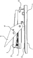
Fig. 3 is the decomposition texture schematic diagram of this labor-saved stapler;
Fig. 4 is the force analysis figure of this labor-saved stapler.
Among the figure, 1, base; 11, base plate; 12, pedestal; 13, folding sole; 2, gland; 21, cutter; 3, order box; 4, auxiliary loam cake; 41, installing hole; 5, force application rod; 6, decorate bonnet; 7, decorate loam cake.
The specific embodiment
Below be specific embodiments of the invention and in conjunction with the accompanying drawings, technical scheme of the present invention is further described, but the present invention be not limited to these embodiment.
Shown in Fig. 1~3, this labor-saved stapler, what comprise the gland 2 that base 1, pressure effect can press down down and be used to place staple between base 1 and gland 2 orders box 3, described base 1 comprises base plate 11 and the pedestal 12 that is connected on the base plate 11, pedestal 12 is fixed on the tail end of base plate 11, and described gland 2, the tail end of ordering box 3 all are hinged with the tail end of pedestal 12.This stapler also comprises an auxiliary loam cake 4, described auxiliary loam cake 4 one ends are articulated in the front end of pedestal 12, the other end is force side and the top that is positioned at gland 2, also be provided with a force application rod 5 that is parallel to gland 2 jointed shafts on the auxiliary loam cake 4, this force application rod 5 is positioned at the top of gland 2, and when the force side of auxiliary loam cake 4 is subjected to downward active force, described force application rod 5 can apply downward active force to the upper surface of gland 2, and press down the force application rod 5 described in the process at auxiliary loam cake 4 can be along gland 2 to reach.
This labor-saved stapler is by increasing an auxiliary loam cake 4, utilize lever principle, reach the labour-saving effect, auxiliary loam cake 4 is across on gland 2, the one end is articulated in pedestal 12 front ends, and the other end is positioned at gland 2 tops, and force application rod 5 also is positioned at the top of gland 2, by pushing the force side of auxiliary loam cake 4, make that the 5 pairs of glands 2 of force application rod on the auxiliary loam cake 4 apply downward pressure.Because the pin joint of auxiliary loam cake 4 is than the front end of the more close base 1 of pin joint of gland 2, therefore, when the force side of the force side of assisting loam cake 4 and gland 2 is positioned at same perpendicular, the ratio of the arm of force that auxiliary loam cake 4 ends and force application rod 5 places are stressed obviously greater than gland 2 glands 2 ends and force application rod 5 stress points the ratio of the stressed arm of force, thereby exert pressure by auxiliary loam cake 4 and can reach the labour-saving effect than exerting pressure by gland 2.Simultaneously, in the process that auxiliary loam cake 4 presses down, force application rod 5 can be along the upper surface of gland 2 gradually to reach, and promptly the application point of 5 pairs of glands 2 of force application rod moves forward gradually, and auxiliary loam cake 4 ends are constant with the ratio of the arm of force of force application rod 5 place's application of forces, and therefore auxiliary loam cake 4 is laborsaving more to pressing down more.
Be illustrated in figure 4 as the simplification force analysis figure of this labor-saved stapler, suppose to press the required pressure size of lower cover 2 distal-most end and be F
1, in order to reach effect same, at force application rod 5 and the required power F that applies in gland 2 contact positions
2=F
1L
1/ L
2For 5 pairs of glands of force application rod 2 are formed and F
2Equal-sized F '
2, need be at the power F that assists loam cake 4 distal-most end to apply
3=F
2L '
2/ L
3L wherein
1Be F
1The arm of force, L
2Be F
2The arm of force, L '
2Be F '
2The arm of force, L
3Be F
3The arm of force.Be F
1=F
2L
2/ L
1F
3=F '
2L '
2/ L
3F then
3=F
1L
1L '
2/ L
3L
2The pin joint of auxiliary loam cake 4 and the pin joint of gland 2 are positioned on the same horizontal plane, under the situation identical of the position of auxiliary loam cake 4 distal-most end with gland 2 distal-most end vertical positions, because the distal-most end of comparatively close gland 2 of the pin joint of auxiliary loam cake 4 and auxiliary loam cake 4, then L '
2/ L
3<L
2/ L
1So F
3<F
1, then push auxiliary loam cake 4 and can reach the labour-saving effect than pushing gland 2.In the process that auxiliary loam cake 4 presses down, force application rod 5 also can be along gland 2 upper surfaces to reach, therefore auxiliary loam cake 4 is past more press down laborsaving more.
In the present embodiment, under the original state, L
3: L '
2=3.8: 1; L
1: L
2=1.9; F then
3=F
1L
1L '
2/ L
3L
2=0.5F
1Therefore, can economize the power of half by pushing auxiliary loam cake 4.
When auxiliary loam cake 4 continues to pressing to gland 2 when contacting with base plate 11, L3 and L '
2Constant rate; L
1: L
2=1.72; Be F
3=F
1L
1L '
2/ L
3L
2=0.45F
1This shows that along with pressing down of auxiliary loam cake 4, this labor-saved stapler can be more and more laborsaving.
As shown in Figure 2, pedestal 12 outsides are arranged with decorates bonnet 6, and described decoration bonnet 6 is connected with base plate 11.Auxiliary loam cake 4 outsides are arranged with decorates loam cake 7, and described decoration loam cake 7 is articulated on the jointed shaft of auxiliary loam cake 4.Decorate bonnet 6 and all adopt plastic material to make, good looking appearance and good hand touch with decoration loam cake 7.
In this labor-saved stapler, gland 2 is provided with cutter 21, and described cutter 21 can pass in the nail road of ordering box 3 staple is pressed down, and is positioned on the described base plate 11 to be provided with folding sole 13 under the cutter 21.Order when being placed with staple in the box 3, to pressing down, make cutter 21 on the gland 2 will order staple in the box 3 after pressing down and penetrating paper, with staple inwardly or outwards turnover by folding sole 13 by auxiliary loam cake 4.Order and be provided with the ejector pin assembly that to order staple forward end promotion all the time in the box 3 in the box 3.Ejector pin assembly in this labor-saved stapler, parts such as gland 2, base 1, folding sole 13 are prior art, do not repeat them here.
Specific embodiment described herein only is that the present invention's spirit is illustrated.The technical staff of the technical field of the invention can make various modifications or replenishes or adopt similar mode to substitute described specific embodiment, but can't depart from spirit of the present invention or surmount the defined scope of appended claims.
Although this paper has used base 1, base plate 11, pedestal 12, folding sole 13, gland 2, cutter 21, orders box 3, auxiliary loam cake 4, installing hole 41, force application rod 5, decorated terms such as bonnet 6, decoration loam cake 7 morely, do not get rid of the possibility of using other term.Using these terms only is in order to describe and explain essence of the present invention more easily; They are construed to any additional restriction all is contrary with spirit of the present invention.
Claims (8)
1. labor-saved stapler, comprise base (1), the gland (2) that the pressure effect can press down down and be positioned at base (1) and gland (2) between be used to place staple order box (3), described gland (2), the tail end of ordering box (3) all is hinged with the tail end of base (1), it is characterized in that, this stapler also comprises an auxiliary loam cake (4), described auxiliary loam cake (4) one ends are articulated in the middle part of base (1), the other end is force side and the top that is positioned at gland (2), described auxiliary loam cake (4) is positioned at place, gland (2) top and is provided with a force application rod (5), when the force side is subjected to downward active force, described force application rod (5) can apply downward active force to the upper surface of gland (2), and press down the force application rod described in the process (5) at auxiliary loam cake (4) can be along gland (2) to reach.
2. labor-saved stapler according to claim 1, it is characterized in that, described auxiliary loam cake (4) has end face and two parallel sides, two sides lay respectively at the both sides of gland (2), two lateral ends are articulated in respectively on the base (1), and the inboard, two sides offers installing hole (41), and above-mentioned force application rod (5) two ends are installed on respectively in the installing hole (41) of two sides.
3. labor-saved stapler according to claim 2, it is characterized in that, described force application rod (5) comprises the back shaft that is fixed on auxiliary loam cake (4) inboard, two sides and is set in the application of force axle in the back shaft outside that described application of force axle can be that rotate in the axle center with the back shaft.
4. according to claim 1 or 2 or 3 described labor-saved staplers, it is characterized in that, described base (1) comprises a base plate (11) and is connected in pedestal (12) on the base plate (11), the tail end of above-mentioned gland (2) and nail box is articulated in the tail end of pedestal (12), and an end of above-mentioned auxiliary loam cake (4) is articulated in the front end of pedestal (12).
5. labor-saved stapler according to claim 4 is characterized in that, described pedestal (12) outside is arranged with decorates bonnet (6), and described decoration bonnet (6) is connected with base plate (11).
6. according to claim 1 or 2 or 3 described labor-saved staplers, it is characterized in that described auxiliary loam cake (4) outside is arranged with decorates loam cake (7), described decoration loam cake (7) is articulated on the jointed shaft of auxiliary loam cake (4).
7. according to claim 1 or 2 or 3 described labor-saved staplers, it is characterized in that, described gland (2) is provided with cutter (21), described cutter (21) can pass in the nail road of ordering box (3) staple is pressed down, and is positioned on the described base plate (11) to be provided with folding sole (13) under the cutter (21).
8. according to claim 1 or 2 or 3 described labor-saved staplers, it is characterized in that described ordering is provided with the ejector pin assembly that can will order the forward end promotion all the time of the interior staple of box (3) in the box (3).
Priority Applications (1)
| Application Number | Priority Date | Filing Date | Title |
|---|---|---|---|
| CN 201110027608 CN102152281B (en) | 2011-01-26 | 2011-01-26 | Labor-saving stapler |
Applications Claiming Priority (1)
| Application Number | Priority Date | Filing Date | Title |
|---|---|---|---|
| CN 201110027608 CN102152281B (en) | 2011-01-26 | 2011-01-26 | Labor-saving stapler |
Publications (2)
| Publication Number | Publication Date |
|---|---|
| CN102152281A true CN102152281A (en) | 2011-08-17 |
| CN102152281B CN102152281B (en) | 2013-05-01 |
Family
ID=44434114
Family Applications (1)
| Application Number | Title | Priority Date | Filing Date |
|---|---|---|---|
| CN 201110027608 Active CN102152281B (en) | 2011-01-26 | 2011-01-26 | Labor-saving stapler |
Country Status (1)
| Country | Link |
|---|---|
| CN (1) | CN102152281B (en) |
Cited By (3)
| Publication number | Priority date | Publication date | Assignee | Title |
|---|---|---|---|---|
| CN102922491A (en) * | 2012-11-08 | 2013-02-13 | 陈群 | Stapling machine |
| CN109202813A (en) * | 2018-10-23 | 2019-01-15 | 凡得雨 | A kind of office's stapler |
| CN109590948A (en) * | 2019-01-15 | 2019-04-09 | 得力集团有限公司 | Labor-saved stapler |
Citations (5)
| Publication number | Priority date | Publication date | Assignee | Title |
|---|---|---|---|---|
| CN2902712Y (en) * | 2006-04-14 | 2007-05-23 | 顺德工业股份有限公司 | labor saving stapler |
| CN200988345Y (en) * | 2006-10-31 | 2007-12-12 | 余斌 | Lever type stapler |
| TWI324098B (en) * | 2007-07-09 | 2010-05-01 | Sdi Corp | |
| CN201580070U (en) * | 2009-12-25 | 2010-09-15 | 旗标文具(深圳)有限公司 | Labor-saving stapler |
| CN201587190U (en) * | 2009-12-23 | 2010-09-22 | 深圳市齐心文具股份有限公司 | Labor-saving stapler |
-
2011
- 2011-01-26 CN CN 201110027608 patent/CN102152281B/en active Active
Patent Citations (5)
| Publication number | Priority date | Publication date | Assignee | Title |
|---|---|---|---|---|
| CN2902712Y (en) * | 2006-04-14 | 2007-05-23 | 顺德工业股份有限公司 | labor saving stapler |
| CN200988345Y (en) * | 2006-10-31 | 2007-12-12 | 余斌 | Lever type stapler |
| TWI324098B (en) * | 2007-07-09 | 2010-05-01 | Sdi Corp | |
| CN201587190U (en) * | 2009-12-23 | 2010-09-22 | 深圳市齐心文具股份有限公司 | Labor-saving stapler |
| CN201580070U (en) * | 2009-12-25 | 2010-09-15 | 旗标文具(深圳)有限公司 | Labor-saving stapler |
Cited By (4)
| Publication number | Priority date | Publication date | Assignee | Title |
|---|---|---|---|---|
| CN102922491A (en) * | 2012-11-08 | 2013-02-13 | 陈群 | Stapling machine |
| CN109202813A (en) * | 2018-10-23 | 2019-01-15 | 凡得雨 | A kind of office's stapler |
| CN109202813B (en) * | 2018-10-23 | 2024-09-06 | 北京立丰天文化传播有限公司 | Stapler for offices |
| CN109590948A (en) * | 2019-01-15 | 2019-04-09 | 得力集团有限公司 | Labor-saved stapler |
Also Published As
| Publication number | Publication date |
|---|---|
| CN102152281B (en) | 2013-05-01 |
Similar Documents
| Publication | Publication Date | Title |
|---|---|---|
| CN102152281B (en) | Labor-saving stapler | |
| CN202528145U (en) | Effort-saving stapler | |
| CN201923841U (en) | High efficient upholstering machine | |
| CN102335903B (en) | Labor-saving stapler | |
| CN202106358U (en) | Labor-saving stapler | |
| CN202225168U (en) | Labor-saving stapler | |
| CN203438188U (en) | Labor-saving stapler | |
| CN108045717B (en) | Engine turnover work or material rest | |
| CN201026726Y (en) | Labor-saving stapler | |
| CN204797657U (en) | Simply press shell ware | |
| CN202805123U (en) | Stapler | |
| CN204055430U (en) | A kind of automotive seat slideway release mechanism | |
| CN201587190U (en) | Labor-saving stapler | |
| CN207807631U (en) | Effort-saving hand Pliers type stapling machine | |
| CN204167150U (en) | A kind of manual override mechanism of earthed switch | |
| CN204195460U (en) | The automatic Da Zao mechanism of polishing machine | |
| CN103406878B (en) | A kind of labor-saved stapler | |
| CN103009059A (en) | Method for assembling rubber sleeves of pedals of motorcycle | |
| CN201419388Y (en) | Labor-saving book stitcher | |
| CN202225171U (en) | Stapler | |
| CN201158034Y (en) | Garbage clamp | |
| CN2543513Y (en) | Cart type walkstick capable of walking on ground | |
| CN202985511U (en) | Movable stapler | |
| CN203543719U (en) | Pressing-down-type slideway assembly | |
| CN203152457U (en) | Novel stringing machine |
Legal Events
| Date | Code | Title | Description |
|---|---|---|---|
| C06 | Publication | ||
| PB01 | Publication | ||
| C10 | Entry into substantive examination | ||
| SE01 | Entry into force of request for substantive examination | ||
| C14 | Grant of patent or utility model | ||
| GR01 | Patent grant |