CN101931247B - Charging system and battery power management method - Google Patents
Charging system and battery power management method Download PDFInfo
- Publication number
- CN101931247B CN101931247B CN 200910148689 CN200910148689A CN101931247B CN 101931247 B CN101931247 B CN 101931247B CN 200910148689 CN200910148689 CN 200910148689 CN 200910148689 A CN200910148689 A CN 200910148689A CN 101931247 B CN101931247 B CN 101931247B
- Authority
- CN
- China
- Prior art keywords
- mentioned
- battery
- temperature
- critical
- mentioned battery
- Prior art date
- Legal status (The legal status is an assumption and is not a legal conclusion. Google has not performed a legal analysis and makes no representation as to the accuracy of the status listed.)
- Active
Links
- 238000007600 charging Methods 0.000 title claims abstract description 60
- 238000007726 management method Methods 0.000 title claims description 18
- 238000010616 electrical installation Methods 0.000 claims description 18
- 230000006698 induction Effects 0.000 claims description 9
- 238000000034 method Methods 0.000 abstract description 4
- 238000010586 diagram Methods 0.000 description 8
- 230000008859 change Effects 0.000 description 6
- WHXSMMKQMYFTQS-UHFFFAOYSA-N Lithium Chemical compound [Li] WHXSMMKQMYFTQS-UHFFFAOYSA-N 0.000 description 3
- 229910052744 lithium Inorganic materials 0.000 description 3
- 238000005516 engineering process Methods 0.000 description 2
- 230000008901 benefit Effects 0.000 description 1
- 230000008878 coupling Effects 0.000 description 1
- 238000010168 coupling process Methods 0.000 description 1
- 238000005859 coupling reaction Methods 0.000 description 1
- 230000003292 diminished effect Effects 0.000 description 1
- 238000007599 discharging Methods 0.000 description 1
- 230000006872 improvement Effects 0.000 description 1
- 230000009467 reduction Effects 0.000 description 1
Images


Landscapes
- Charge And Discharge Circuits For Batteries Or The Like (AREA)
Abstract
A charging system and a method for managing the electric quantity of a battery comprise that when the temperature of the battery is lower than a first critical temperature, the battery is normally charged at 4.2V. If the temperature of the battery is higher than the first threshold temperature but lower than a second threshold temperature, and if the electric quantity of the battery is lower than a first threshold voltage or capacity, the battery is continuously charged. Conversely, when the battery temperature is between the first critical temperature and the second critical temperature and the electric quantity of the battery is higher than the first critical voltage or capacity, the battery charging is stopped. If the battery temperature is higher than a second critical temperature, the charging is stopped regardless of the battery voltage.
Description
Technical field
The invention relates to a kind of charging method of battery, and particularly relevant for a kind of at high temperature to the technology of charging of battery.
Background technology
Typical battery charger comprises three control circuits, is respectively fixed current controling circuit, constant voltage control circuit and constant temperature control circuit.On using, when beginning the less battery charge of an electric weight, battery charger enters constant current mode.At this moment, fixed current controling circuit can be kept a stable charging current and comes battery charge.General known charger in the temperature of battery between 0 ℃ between 45 ℃ the time, as long as the voltage of confirming battery during less than 4.2V, just can continue with constant current mode battery charge.When the voltage of battery arrives 4.2V by the time, then switch to constant voltage mode, this moment, electric current slowly diminished until filling the full charging that promptly stops.
When the voltage of battery reached a predeterminated voltage, general typical case was 4.2V, and then known charger enters constant voltage mode.At this moment, the constant voltage control circuit in the known charge device can be kept fixed voltage to battery charge.When the temperature of temperature control circuit detecting battery is higher than 45 ℃, cause expansion, leakage or the like possibility for fear of battery because of being in the 4.2V high-temperature charging, therefore known charger, can not stop battery charge even cell voltage reaches 4.2V as yet during as 45 ℃ immediately when reaching the temperature that sets.But battery 45~60 ℃ can less constant-voltage charge, charge as 4.1V.And known charger can't be accomplished the function of variations in temperature switched voltage, also can't charge even make that voltage is very low between 45~60 ℃ of temperature.Therefore, under traditional situation, the situations that can't be higher than 45 degree in temperature are to battery charge, and must equitemperature be lower than 45 when spending, and just can charge, and the practice of improvement is arranged.
Summary of the invention
The invention provides a kind of charging system, can allow battery under wider temperature range, battery be charged.Need not change under too many hardware or the charging chip, battery can charge to the method for high voltage in high temperature.
The invention provides a kind of management method of battery electric quantity, can more effectively under different temperatures, charge normal and reduce problem generations such as battery expansion.
The invention provides a kind of charging system, can charge more widely a battery.The present invention includes charger and detecting unit.Wherein, detecting unit can measure a plurality of electric parameters of battery.When the temperature of battery was lower than one first critical temperature, charger can charge normal battery.And when but the temperature of battery was higher than first critical temperature is lower than one second critical temperature, detecting unit can judge whether the electric weight of battery is lower than one first critical voltage.If battery temperature is between first critical temperature and second critical temperature, and the electric weight of battery is when being lower than first critical voltage, then charger continues battery charge.Otherwise, when battery temperature between first critical temperature and second critical temperature, and the electric weight of battery is when being higher than first critical voltage, then detecting unit can make charger stop battery charge.When battery temperature is higher than one second critical temperature,, can also this detecting unit conduct end the instrument that charges except that charging chip can stop the charged state.
In one embodiment of this invention, battery can couple an electrical installation when charging.Therefore, when detecting unit is found the temperature of battery and electric weight respectively greater than second critical temperature and greater than one second critical voltage, if battery couples an electrical installation, then detecting unit can start this electrical installation, and makes battery to this electrical installation discharge.Wherein, second critical voltage is less than first critical voltage.
From another viewpoint, the present invention also provides a kind of management method of battery electric quantity, comprises when the temperature of battery is lower than one first critical temperature, then battery is charged normal.Though be lower than one second critical temperature if the temperature of battery is higher than this first critical temperature, and when the electric weight of battery is lower than one first critical voltage, then continue to battery charge.Otherwise, when battery temperature between first critical temperature and second critical temperature, and the electric weight of battery then stops battery charge when being higher than first critical voltage.
In addition, if when battery temperature is higher than second critical temperature, then stop battery charge equally.
Because the present invention can surpass one first critical temperature at battery, but and no show second critical temperature, and battery electric quantity is when being lower than one first critical voltage, do not change under too many hardware or the charging chip sustainable to battery charge.Therefore, the present invention can promote battery effectively and charge under wider temperature range, and also can protect battery to be difficult for taking place because of producing problems such as expansion under the high temperature and high pressure environment when charging.
For above-mentioned feature and advantage of the present invention can be become apparent, embodiment cited below particularly, and cooperate appended graphic being described in detail below.
Description of drawings
Figure 1 shows that flow chart of steps according to the management method of a kind of battery electric quantity of a preferred embodiment of the present invention.
Figure 2 shows that system block diagrams according to a kind of charging system of one embodiment of the invention.
Figure 3 shows that system block diagrams according to a kind of charging system of another embodiment of the present invention.
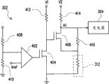
Figure 4 shows that circuit diagram according to the detecting unit of Fig. 3 of one embodiment of the invention.
Figure 5 shows that according to a kind of battery of a preferred embodiment of the present invention when the charging and the circuit diagram that couples of an electrical installation.
Embodiment
Figure 1 shows that flow chart of steps according to the management method of a kind of battery electric quantity of a preferred embodiment of the present invention.Please refer to Fig. 1, the battery that management method was suitable for that present embodiment provided for example is a lithium battery.When the user carried out charging procedure to battery, present embodiment can to battery charge, and carry out step S104 as described in the step S102, judges exactly whether the temperature of battery is higher than one first critical temperature.In the present embodiment, first critical temperature is preferable but not limit be 45 ℃.
If the temperature of battery does not surpass first critical temperature (being exactly the "No" that step S104 is indicated), then can continue step S102, so that battery is charged normal.Yet, if when the temperature of battery surpasses first critical temperature (being exactly the "Yes" that step S104 is indicated), the further execution in step S106 of present embodiment judges exactly whether battery temperature is higher than one second critical temperature.Wherein, second critical temperature is preferable but not limit be 60 ℃.
Specifically, if though the temperature of battery surpasses first critical temperature, but during less than second critical temperature (being exactly the "No" that step S106 is indicated), present embodiment can be selected to carry out step S108, is exactly whether the electric weight of further judging battery surpasses one first critical voltage.In the present embodiment, first critical voltage can be greater than 3.1V, but less than 4.2V, for example is 4.1V.
In step S108, if judge that battery temperature is between first critical temperature and second critical temperature, and when the electric weight of battery does not surpass first critical voltage (being exactly the "No" that step S108 is indicated), then get back to step S102, and battery is continued charging.
Get back to step S106, if battery temperature has surpassed second critical temperature (being exactly the "Yes" that step S106 is indicated), then present embodiment can stop battery charge as described in the step S110.Relatively, even if battery temperature does not surpass second critical temperature, just its temperature is between first critical temperature and second critical temperature, but battery electric quantity has surpassed first critical voltage (being exactly the "Yes" that step S108 is indicated), then present embodiment is still as described in the step S110, stop battery charge, to avoid the possible expansion issues of battery etc.
Figure 2 shows that system block diagrams according to a kind of charging system of one embodiment of the invention.Please refer to Fig. 2, the charging system 200 that present embodiment provided can be to for example being battery 210 chargings of lithium battery.Charging system 200 comprises detecting unit 202 and charger 204.Wherein, detecting unit 202 couples charger 204.And in certain embodiments, detecting unit 202 can be realized with the form of software.And in other embodiment, 202 of detecting units can utilize the form of microprocessor to realize, the present invention does not limit.
In the present embodiment, charging system 200 also comprises switch element 206, and it couples charger 204 1 ends and battery 210 1 ends respectively.When battery 210 is installed in when charging on the charging system 200, charger 204 can control switch unit 206 conductings.Then, charger 204 judges whether the voltage of output arrives a predeterminated voltage, (and export a detecting as a result DET give charger 204).In general, this predeterminated voltage for example is 4.2V.If the voltage of charger 204 outputs is the no show preset value also, then provide certain electric current to battery 210 charging, and this to decide current value for example be 500mA.
Relatively, if the voltage of charger 204 outputs has arrived predeterminated voltage, then 204 pairs of batteries 210 of charger provide the certain voltage source.In the present embodiment, this current potential of deciding voltage source can be identical with predeterminated voltage, all be 4.2V, yet the present invention do not limit with this.
In the present embodiment, battery 210 can dispose a detecting unit 212.And detecting unit 202 just can be obtained a plurality of real-time electric parameter information of battery 210 by detecting unit 212.These electric parameters comprise temperature, voltage, electric current of battery etc.After detecting unit 202 obtains the real-time electric parameter of battery 210, it can be used as detecting as a result DET deliver to charger 204.As described in Figure 1, when the temperature of battery surpassed one first critical temperature (for example 45 ℃), then detecting unit 202 can judge whether the electric weight of battery 210 surpasses one first critical voltage (for example 4.1V).
At this moment, if though the temperature of battery 210 surpasses first critical temperature, the electric weight that stores does not surpass first critical voltage, and then charger 204 continues battery 210 chargings.Relatively, if the temperature of battery 210 not only surpasses first critical temperature, and the electric weight that stores of battery 210 is when also surpassing first critical voltage, and then charger 204 can be according to detecting DET and switch element 206 is opened circuit as a result, to stop battery 210 chargings.In addition, if the temperature of battery 210 constantly rises, and when surpassing one second critical temperature (for example 60 ℃), then charger 204 equally can be according to detecting DET and switch element 206 is opened circuit as a result, to stop battery 210 chargings.In addition, also can disconnect 206 and then stop to charge by charger 204 itself without detecing side unit.
Though in Fig. 2, detecting unit 212 is to be configured in the battery 210, yet in other embodiments, detecting unit 212 also can be configured in charger 204 or independently coexist as in the electrical installation individually, does not influence spirit of the present invention.
Figure 3 shows that system block diagrams according to a kind of charging system of another embodiment of the present invention.Please refer to Fig. 3, charging system that present embodiment provides 300 also can be to for example being battery 310 chargings of lithium battery.In charging system 300, also comprise detecting unit 302, charger 304 and switch element 306.Wherein, detecting unit 302 can couple the positive pole and the negative pole of battery 310, and can couple charger 304.In addition, 304 of chargers can be coupled to battery 310 by switch element 306.
In the present embodiment more specifically, battery 310 does not have the detecting unit 212 of allocation plan 2.Therefore, detecting unit 302 needs to detect the electric weight of battery 310 by measuring the voltage difference of battery 310 positive poles and negative pole.In addition, battery 310 also comprises a thermal induction element 312, for example is thermistor.The electrical characteristic of this thermal induction element 312 for example is a resistance value, can change along with the variation of battery 310 ambient temperature.Therefore, charger 304 can be judged the temperature of battery 310 by the electrical characteristic of thermal induction element 312.Other mode of operation of present embodiment is all identical with Fig. 2, seldom gives unnecessary details at this.
Figure 4 shows that circuit diagram according to the detecting unit of Fig. 3 of one embodiment of the invention.Please refer to Fig. 4, detecting unit 302 comprises comparator 402, switching transistor 404 and 406 and resistance 408,410,412,414 and 416.Wherein, the first input end of comparator 402 can receive the output voltage V bat of battery 310, i.e. voltage difference between battery 310 positive poles and negative pole by resistance 408.In addition, the first input end of comparator 402 can also pass through resistance 410 ground connection.Second input of comparator 402 then can couple a reference voltage Vref.The output of comparator 402 then couples the gate terminal of switching transistor 404, and first source of switching transistor 404/drain end couples the first bias voltage V1 by resistance 412, and its second source/drain end then is a ground connection.In addition, the gate terminal of switching transistor 406 is coupled to the first source/drain end of switching transistor 404, and first source of switching transistor 406/drain end is coupled to the second bias voltage V2 by resistance 414.Second source of switching transistor 406/drain end can pass through thermal induction element 312 ground connection, and the first source/drain end that is coupled to switching transistor 406 by resistance 416 forms node A1, and node A1 is coupled to the charger 304 reception detectings connectivity port of DET as a result.In the present embodiment, switching transistor 404 and 406 the two can be nmos pass transistor.
Please continue with reference to Fig. 4, what comparator 402 first input ends were received is the partial pressure value of the output voltage V bat of battery 310.When cell voltage Vbat surpassed the first above-mentioned critical voltage, then comparator 402 outputs were high potential, cause switching transistor 404 conductings, and switching transistor 406 gate terminal current potentials are pulled down to earthing potential.Therefore, the state of switching transistor 406 for opening circuit.At this moment, the current potential VA1 of node A1 can be expressed as follows:
Wherein R1, R2, R3 are respectively resistance 414 and 416 and the resistance value of thermal induction element 312.And the resistance value of thermal induction element 312 can change along with variation of temperature.
In addition, when cell voltage Vbat does not surpass first critical voltage, then the output of comparator 402 is an electronegative potential, therefore causes switching transistor 404 to open circuit.At this moment, the current potential of switching transistor 406 gate terminal is pulled to V1, and causes switching transistor 406 conductings.In other words, resistance 416 can be considered short circuit.Therefore, the current potential VA1 of node A1 then can be expressed as follows:
By (1) and (2) formula as can be known, under identical temperature, just have under the identical resistance current potential of the A1 of node when cell voltage Vbat surpasses first critical voltage, the current potential of node A1 in the time of can being lower than first critical voltage above cell voltage Vbat at thermal induction element 312.In other words, when cell voltage was lower than first critical voltage, the temperature by charging that charger 304 sets was higher, for example is 60 ℃; When cell voltage surpasses first critical voltage, make charger 304 reach of the setting of reduction charger via such circuit by charging temperature by the change of resistance or dividing potential drop, for example be 45 ℃.Illustrate: when cell voltage Vbat surpassed first critical voltage, the temperature of the battery 310 that charger 304 can allow was lower.For example, when cell voltage Vbat surpasses 4.1V, and the temperature of battery 310 is when being higher than 45 ℃ (between 60 ℃), and charger 304 will open circuit switch element 306, to stop battery 310 chargings.On the contrary, Vbat is lower than 4.1V when cell voltage, though the temperature of battery 310 between 45 ℃ to 60 ℃, then charger 304 still can make switch element 306 conductings, and continues battery 310 chargings.
Figure 5 shows that according to a kind of battery of a preferred embodiment of the present invention when the charging and the circuit diagram that couples of an electrical installation.Please refer to Fig. 5, the charging system 500 in the present embodiment comprises detecting unit 502, charger 504 and switch element 506 equally, and three's coupling mode is identical with above two embodiment, seldom gives unnecessary details at this.In some cases, battery 510 still couples an electrical installation 512 when charging.This situation just looks like that the user uses so-called simple type charger (trip fills or car fills), and directly the battery that is installed in the electrical installation (similarly being mobile phone) is charged.
Please continue with reference to Fig. 5, in the present embodiment, when the temperature of battery 510 surpassed the second above-mentioned critical temperature, charger 504 was except opening circuit switch element 506, in other embodiment, detecting unit 502 can also judge whether the electric weight of battery 510 surpasses one second critical voltage.Wherein, second critical voltage for example is 3.8V less than first critical voltage.
Though if the temperature of battery 510 surpasses second critical temperature, when the electric weight of battery 510 did not also surpass second critical voltage, then charger 504 was not done other disposal except making switch element 506 opens circuit.Otherwise, if the temperature of battery 510 not only temperature surpasses second critical temperature, and the electric weight of battery 510 also surpasses second critical voltage, then make switch element 506 opens circuit except charger 504, detecting unit 502 can also start electrical installation 512, makes battery 510 begin electrical installation 512 discharges.Thus, present embodiment can avoid battery 510 to cause problems such as expansion because store too high electric weight under the environment of excessive temperature.Trip fills or car fills even do not have, and discharging function also is suitable for.In addition, charging system 500 also can be in electrical installation 512.
In sum because the present invention is when battery charge, if the temperature of judging battery between first critical temperature and second critical temperature, but when the electric weight of battery surpasses first critical voltage, continue battery charge.Therefore, the present invention can make battery charge in temperature range widely.
In addition, the present invention when battery charge, if though the temperature of judging battery between first critical temperature and second critical temperature, yet the electric weight of battery surpasses first critical voltage, or the temperature of judging battery then stops battery charge above second critical temperature.So, just can protect battery when charging, can not cause problems such as expansion because of high temperature.
Though the present invention discloses as above with embodiment; right its is not in order to limit the present invention; have in the technical field under any and know the knowledgeable usually; without departing from the spirit and scope of the present invention; when doing a little change and retouching, so protection scope of the present invention is as the criterion when looking claims person of defining.
Claims (23)
1. charging system be suitable for battery charge be is characterized in that, and above-mentioned charging system comprises:
Charger couples above-mentioned battery, with to its charging; And
Detecting unit couples above-mentioned charger and above-mentioned battery, to measure a plurality of electrical parameters of above-mentioned battery;
Wherein when the temperature of above-mentioned battery was lower than first critical temperature, then above-mentioned charger charged normal above-mentioned battery,
When the temperature of above-mentioned battery was higher than above-mentioned first critical temperature but is lower than second critical temperature, then above-mentioned detecting unit judged whether the electric weight of above-mentioned battery is lower than first critical voltage;
When above-mentioned battery temperature between above-mentioned first critical temperature and above-mentioned second critical temperature, and the electric weight of above-mentioned battery is when being lower than above-mentioned first critical voltage, then above-mentioned charger continues above-mentioned battery charge;
And when above-mentioned battery temperature between above-mentioned first critical temperature and above-mentioned second critical temperature, and the electric weight of above-mentioned battery is when being higher than above-mentioned first critical voltage, then above-mentioned charger stops above-mentioned battery charge;
Wherein work as above-mentioned battery and couple electrical installation, and when the temperature of above-mentioned battery and electric weight during respectively greater than above-mentioned second critical temperature and greater than second critical voltage, then above-mentioned detecting unit starts above-mentioned electrical installation, and above-mentioned battery is discharged to above-mentioned electrical installation, wherein above-mentioned second critical voltage is less than above-mentioned first critical voltage.
2. charging system according to claim 1 is characterized in that, wherein when above-mentioned battery temperature was higher than above-mentioned second critical temperature, then above-mentioned charger stopped above-mentioned battery charge.
3. charging system according to claim 1 is characterized in that, wherein above-mentioned battery has detecting unit, and above-mentioned detecting unit obtains a plurality of electric parameters of above-mentioned battery by above-mentioned detecting unit.
4. charging system according to claim 3 is characterized in that, wherein above-mentioned detecting unit obtains real-time electric weight of above-mentioned battery and temperature by above-mentioned detecting unit.
5. charging system according to claim 1 is characterized in that, wherein above-mentioned detecting unit passes through to measure the positive pole of above-mentioned battery and the voltage difference of negative pole, and obtains the electric weight of above-mentioned battery.
6. charging system according to claim 1 is characterized in that, wherein above-mentioned battery has thermal induction element, and above-mentioned detecting unit is judged the temperature of above-mentioned battery according to the resistance of above-mentioned thermal induction element.
7. charging system according to claim 1 is characterized in that, wherein above-mentioned second critical voltage greater than 3.1V less than 4.1V.
8. charging system according to claim 7 is characterized in that, wherein above-mentioned second critical voltage is 3.8V.
9. charging system according to claim 1 is characterized in that, wherein above-mentioned first critical voltage greater than 3.1V less than 4.2V.
10. charging system according to claim 9 is characterized in that, wherein above-mentioned first critical voltage is 4.1V.
11. charging system according to claim 1 is characterized in that, wherein above-mentioned first critical temperature is 45 ℃.
12. charging system according to claim 1 is characterized in that, wherein above-mentioned second critical temperature is 60 ℃.
13. the management method of a battery electric quantity is characterized in that, comprises the following steps:
When the temperature of above-mentioned battery is lower than first critical temperature, then above-mentioned battery is charged normal;
When the temperature of above-mentioned battery is higher than above-mentioned first critical temperature but is lower than second critical temperature, and when the electric weight of above-mentioned battery is lower than first critical voltage, then continue above-mentioned battery charge; And
When above-mentioned battery temperature between above-mentioned first critical temperature and above-mentioned second critical temperature, and the electric weight of above-mentioned battery then stops above-mentioned battery charge when being higher than above-mentioned first critical voltage;
When above-mentioned battery couples electrical installation, and when the temperature of above-mentioned battery and electric weight during respectively greater than above-mentioned second critical temperature and greater than second critical voltage, then start above-mentioned electrical installation, and above-mentioned battery is discharged to above-mentioned electrical installation, wherein above-mentioned second critical voltage is less than above-mentioned first critical voltage.
14. management method according to claim 13 is characterized in that, wherein when above-mentioned battery temperature is higher than above-mentioned second critical temperature, then stops above-mentioned battery charge.
15. management method according to claim 13 is characterized in that, wherein measures the step of above-mentioned battery electric quantity and temperature, comprises from battery reading a plurality of real-time electric parameters.
16. management method according to claim 13 is characterized in that, wherein measures the step of above-mentioned battery electric quantity, comprises measuring the voltage difference between above-mentioned anode and the negative pole and obtaining.
17. management method according to claim 13 is characterized in that, wherein measures the step of above-mentioned battery temperature, comprises the temperature that measures above-mentioned battery context and obtains.
18. management method according to claim 13 is characterized in that, wherein above-mentioned second critical voltage greater than 3.1V less than 4.1V.
19. management method according to claim 18 is characterized in that, wherein above-mentioned second critical voltage is 3.8V.
20. management method according to claim 13 is characterized in that, wherein above-mentioned first critical voltage greater than 3.1V less than 4.2V.
21. management method according to claim 20 is characterized in that, wherein above-mentioned first critical voltage is 4.1V.
22. management method according to claim 13 is characterized in that, wherein above-mentioned first critical temperature is 45 ℃.
23. management method according to claim 13 is characterized in that, wherein above-mentioned second critical temperature is 60 ℃.
Priority Applications (1)
| Application Number | Priority Date | Filing Date | Title |
|---|---|---|---|
| CN 200910148689 CN101931247B (en) | 2009-06-26 | 2009-06-26 | Charging system and battery power management method |
Applications Claiming Priority (1)
| Application Number | Priority Date | Filing Date | Title |
|---|---|---|---|
| CN 200910148689 CN101931247B (en) | 2009-06-26 | 2009-06-26 | Charging system and battery power management method |
Publications (2)
| Publication Number | Publication Date |
|---|---|
| CN101931247A CN101931247A (en) | 2010-12-29 |
| CN101931247B true CN101931247B (en) | 2013-07-24 |
Family
ID=43370256
Family Applications (1)
| Application Number | Title | Priority Date | Filing Date |
|---|---|---|---|
| CN 200910148689 Active CN101931247B (en) | 2009-06-26 | 2009-06-26 | Charging system and battery power management method |
Country Status (1)
| Country | Link |
|---|---|
| CN (1) | CN101931247B (en) |
Families Citing this family (9)
| Publication number | Priority date | Publication date | Assignee | Title |
|---|---|---|---|---|
| CN103904379B (en) * | 2012-12-27 | 2017-06-27 | 联想(北京)有限公司 | The method and electronic equipment of a kind of protection battery |
| CN104242251A (en) * | 2013-06-06 | 2014-12-24 | 深圳富泰宏精密工业有限公司 | Battery with temperature protection function |
| CN104518206B (en) * | 2013-09-26 | 2017-11-28 | 联想(北京)有限公司 | A kind of rechargeable battery, method and apparatus |
| CN104104135A (en) * | 2014-07-07 | 2014-10-15 | 程宇航 | Charging apparatus, charging method and device |
| CN104319426B (en) * | 2014-08-25 | 2016-06-22 | 江苏华东锂电技术研究院有限公司 | The method that the capacity of lithium ion battery is managed |
| CN107171373A (en) * | 2016-03-07 | 2017-09-15 | 中兴通讯股份有限公司 | Battery protecting method and device, terminal |
| CN109856462A (en) * | 2019-01-28 | 2019-06-07 | 深圳供电局有限公司 | Electromagnetic field measuring probe, electromagnetic field measuring system and control method |
| TWI695564B (en) * | 2019-09-03 | 2020-06-01 | 飛宏科技股份有限公司 | Temperature dependent current and pulse controlled charging method for a battery charger |
| CN114665558A (en) * | 2022-04-07 | 2022-06-24 | 济宁市海豚科技有限公司 | Wireless charging method |
Family Cites Families (1)
| Publication number | Priority date | Publication date | Assignee | Title |
|---|---|---|---|---|
| US7176654B2 (en) * | 2002-11-22 | 2007-02-13 | Milwaukee Electric Tool Corporation | Method and system of charging multi-cell lithium-based batteries |
-
2009
- 2009-06-26 CN CN 200910148689 patent/CN101931247B/en active Active
Also Published As
| Publication number | Publication date |
|---|---|
| CN101931247A (en) | 2010-12-29 |
Similar Documents
| Publication | Publication Date | Title |
|---|---|---|
| CN101931247B (en) | Charging system and battery power management method | |
| CN206432703U (en) | Super-charge super-discharge protection circuit, protection device, battery management system and electric automobile | |
| CN101465557B (en) | Portable device and battery pack for the same | |
| CN106663944B (en) | electrical storage system | |
| US9484763B2 (en) | Battery pack and method of controlling the same | |
| JP5289083B2 (en) | Secondary battery abnormality detection device and secondary battery device | |
| CN103227482B (en) | Charge controller with protection function and battery pack | |
| CN102163839B (en) | Protection circuit and electronic device | |
| CN101425698B (en) | Battery pack, method of charging secondary battery and battery charger | |
| EP3018791B1 (en) | Power storage device and power storage device control method | |
| CN100364205C (en) | Remaining capacity calculation method and battery pack for secondary battery | |
| TWI396357B (en) | Charging system and battery power management method | |
| KR101387733B1 (en) | Battery pack, battery pack arrangement and electric apparatus | |
| CN102204060B (en) | Protection circuit and battery pack | |
| US20100196747A1 (en) | Battery pack | |
| CN101777782A (en) | Battery pack and method of controlling the same | |
| KR20140065951A (en) | Battery management system and driving method thereof | |
| CN105599632A (en) | EV-based (electric vehicle based) battery management method and system | |
| CN106684959A (en) | Power storage system and secondary battery control method | |
| CN105871021B (en) | Battery management system and method for battery of electric bicycle group quick charge | |
| CN102122734A (en) | Battery pack | |
| CN103166289A (en) | Mobile terminal and method for detecting battery voltage in charging | |
| CN104505905A (en) | Single-charged and series-discharged lithium battery pack | |
| CN102231769A (en) | Method for turning on mobile phone with over-discharged cell and mobile phone | |
| US9360530B2 (en) | Method and system for energy storage capacity estimation of battery cells |
Legal Events
| Date | Code | Title | Description |
|---|---|---|---|
| C06 | Publication | ||
| PB01 | Publication | ||
| C10 | Entry into substantive examination | ||
| SE01 | Entry into force of request for substantive examination | ||
| C14 | Grant of patent or utility model | ||
| GR01 | Patent grant |