CN101742786A - light emitting device - Google Patents
light emitting device Download PDFInfo
- Publication number
- CN101742786A CN101742786A CN200810177768A CN200810177768A CN101742786A CN 101742786 A CN101742786 A CN 101742786A CN 200810177768 A CN200810177768 A CN 200810177768A CN 200810177768 A CN200810177768 A CN 200810177768A CN 101742786 A CN101742786 A CN 101742786A
- Authority
- CN
- China
- Prior art keywords
- circuit
- light emitting
- current
- lighting
- power
- Prior art date
- Legal status (The legal status is an assumption and is not a legal conclusion. Google has not performed a legal analysis and makes no representation as to the accuracy of the status listed.)
- Pending
Links
- 238000001514 detection method Methods 0.000 claims abstract description 37
- 239000002699 waste material Substances 0.000 description 6
- 238000010586 diagram Methods 0.000 description 5
- 238000000034 method Methods 0.000 description 3
- 239000003990 capacitor Substances 0.000 description 2
- 230000005669 field effect Effects 0.000 description 1
- 239000004973 liquid crystal related substance Substances 0.000 description 1
- 238000012986 modification Methods 0.000 description 1
- 230000004048 modification Effects 0.000 description 1
- 239000004065 semiconductor Substances 0.000 description 1
Images


Landscapes
- Circuit Arrangement For Electric Light Sources In General (AREA)
Abstract
一种发光装置包含一电源供应电路、一发光电路及一检测控制电路。电源供应电路输出一电流。发光电路与电源供应电路电连接,并具有串联连接的多个发光单元。各发光单元具有相互电连接的一发光元件及一开关元件。检测控制电路检测发光电路的功率、或电压、或电流、或开关状态,而停止供应电流至发光电路。

A light-emitting device includes a power supply circuit, a light-emitting circuit and a detection control circuit. The power supply circuit outputs a current. The light-emitting circuit is electrically connected to the power supply circuit and has a plurality of light-emitting units connected in series. Each light-emitting unit has a light-emitting element and a switch element electrically connected to each other. The detection control circuit detects the power, voltage, current, or switch state of the light-emitting circuit and stops supplying current to the light-emitting circuit.
Description
技术领域technical field
本发明关于一种发光装置。The invention relates to a light emitting device.
背景技术Background technique
在液晶显示设备(LCD apparatus)中,一般是使用冷阴极荧光灯作为背光模块的发光单元。然而,因为冷阴极荧光灯对于色彩的表现较不如发光二极管(light-emitting diode,LED),因此,在发光二极管的技术逐渐成熟的前提下,目前已有业者将发光二极管作为发光装置使用。In a liquid crystal display device (LCD apparatus), a cold cathode fluorescent lamp is generally used as a light emitting unit of a backlight module. However, because CCFLs are not as good as light-emitting diodes (LEDs) in terms of color performance, there are currently industry players using light-emitting diodes as light-emitting devices under the premise that the technology of light-emitting diodes is gradually maturing.
请参照图1所示,习知的发光装置1具有一电源供应电路11及多个发光二极管12,其通过电源供应电路11提供电源至各发光二极管12,以使各发光二极管12发光。Referring to FIG. 1 , a conventional
然而,在习知技术中,并未利用其它的检测电路来检测各发光二极管12的状态。因此,当有任何的发光二极管12损坏形成开路O时,也没有其它控制电路来关闭电源供应电路11,使其停止供应电源至损坏的发光二极管12中。另外,若发光二极管12已达最大亮度,电源供应电路11也无法相应地调整提供至发光二极管12的电源大小,而这些情况都会造成电能的损耗与浪费。However, in the prior art, no other detection circuits are used to detect the states of the
因此,如何能对发光装置的电源做更有效的控制,并减少电能的损耗与浪费,实属当前重要课题之一。Therefore, how to more effectively control the power supply of the light emitting device and reduce the loss and waste of electric energy is one of the current important issues.
发明内容Contents of the invention
有鉴于上述课题,本发明的目的为提供一种能对发光电路的电源做更有效的控制,以减少电能损耗与浪费的发光装置。In view of the above problems, the object of the present invention is to provide a light emitting device capable of more effectively controlling the power supply of the light emitting circuit to reduce power consumption and waste.
为达上述目的,依据本发明的一种发光装置包含一电源供应电路、一发光电路及一检测控制电路。电源供应电路输出一电流。发光电路与电源供应电路电连接,并具有串联连接的多个发光单元。各发光单元具有相互电连接的一发光元件及一开关元件。检测控制电路检测发光电路的功率、或电压、或电流、或开关状态,而停止供应电流至发光电路。To achieve the above purpose, a lighting device according to the present invention includes a power supply circuit, a lighting circuit and a detection control circuit. The power supply circuit outputs a current. The light emitting circuit is electrically connected to the power supply circuit, and has a plurality of light emitting units connected in series. Each light emitting unit has a light emitting element and a switching element electrically connected to each other. The detection control circuit detects the power, or voltage, or current, or switch state of the lighting circuit, and stops supplying current to the lighting circuit.
承上所述,依据本发明的发光装置先通过检测控制电路检测发光电路的功率、或电压、或电流、或开关状态,而停止供应电流至发光电路。因此,本发明的发光装置可依据发光电路的状态,来对应地控制发光电路电流的供应,由此即可减少不必要的电能损耗与浪费。As mentioned above, the light emitting device according to the present invention first detects the power, voltage, current, or switch state of the light emitting circuit through the detection control circuit, and then stops supplying current to the light emitting circuit. Therefore, the light emitting device of the present invention can control the supply of current of the light emitting circuit correspondingly according to the state of the light emitting circuit, thereby reducing unnecessary power loss and waste.
附图说明Description of drawings
图1为一种习知的发光装置示意图;FIG. 1 is a schematic diagram of a known light-emitting device;
图2为本发明的发光装置示意图;以及FIG. 2 is a schematic diagram of a light-emitting device of the present invention; and
图3及图4为本发明的发光装置不同变化样式示意图。3 and 4 are schematic diagrams of different variations of the light emitting device of the present invention.
元件符号说明:Description of component symbols:
1、2、2a、2b:发光装置1, 2, 2a, 2b: light emitting device
11、3:电源供应电路11.3: Power supply circuit
12:发光二极管12: LED
4:发光电路4: Lighting circuit
41:发光单元41: Lighting unit
411:发光元件411: Light emitting element
412:开关元件412: switching element
5、5a、5b:检测控制电路5, 5a, 5b: detection control circuit
51:亮度控制单元51: Brightness control unit
511:比较元件511: Comparing components
512:电荷储存元件512: Charge storage element
513:感测元件513: sensing element
52:检测单元52: Detection unit
53:电源控制单元53: Power control unit
6:旁路开关电路6: Bypass switch circuit
F:反馈信号F: Feedback signal
I:电流I: Current
O:开路O: open circuit
具体实施方式Detailed ways
以下将参照相关附图,说明依据本发明的一种发光装置,其中相同元件以相同符号表示。A light emitting device according to the present invention will be described below with reference to related drawings, wherein the same elements are denoted by the same symbols.
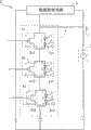
请参照图2所示,本发明的发光装置2包含一电源供应电路3、一发光电路4以及一检测控制电路5。Please refer to FIG. 2 , the light emitting device 2 of the present invention includes a power supply circuit 3 , a light emitting circuit 4 and a
电源供应电路3输出一电流I,而电流I可为直流(DC)或交流(AC)。发光电路4与电源供应电路3电连接,并具有串联连接的多个发光单元41。各发光单元41具有相互电连接的一发光元件411及一开关元件412。其中,在本实施例中,以发光单元41具有多个发光元件411,且开关元件412与这些发光元件411并联连接为例作说明,然而其并非是限制性的。The power supply circuit 3 outputs a current I, and the current I can be direct current (DC) or alternating current (AC). The light emitting circuit 4 is electrically connected to the power supply circuit 3 and has a plurality of
发光元件411例如可为一发光二极管或一冷阴极荧光灯。在本实施例中,发光元件411以发光二极管为例作说明,然而其并非是限制性的。开关元件412例如为双极晶体管(BJT)或金属-氧化物-半导体场效应晶体管(MOSFET),在本实施例中,开关元件412以MOSFET作说明。The light emitting element 411 can be, for example, a light emitting diode or a CCFL. In this embodiment, the light emitting element 411 is illustrated by taking a light emitting diode as an example, but it is not limiting. The
检测控制电路5检测发光电路4的功率、或电压、或电流、或开关状态。其中,功率例如为发光电路4的电功率或发光功率,电压或电流为发光电路4的端电压大小或电流大小,而开关状态为这些开关元件412的开关状态。The
因此,当检测控制电路5检测到发光电路4的功率、或电压、或电流小于等于一阈值时,检测控制电路5即可使电源供应电路3停止供应电流I至发光电路4。Therefore, when the
另外,若检测控制电路5检测发光电路4的开关状态,当至少一开关元件412为关闭(turn off)状态,即表示至少一发光元件411为开启(turn on)状态,则发光电路4为开启状态,此时,检测控制电路5会使电源供应电路3继续供应电流I至发光电路4。但是,当全部开关元件412为开启状态,即表示这些发光元件411全为关闭状态,则发光电路4为关闭状态,检测控制电路5会关闭电源供应电路3以停止供应电流I至发光电路4。In addition, if the
由此,本实施例的发光装置2可依据发光电路4的状态,来对应地控制发光电路4的电流的输入,据此即可减少不必要的电能损耗与浪费。Therefore, the light emitting device 2 of this embodiment can control the current input of the light emitting circuit 4 correspondingly according to the state of the light emitting circuit 4 , thereby reducing unnecessary power loss and waste.
另外,请参照图3所示,其为本实施例的发光装置2a的另一变化样式示意图。发光装置2a的检测控制电路5a还可包含一亮度控制单元51,其与这些发光单元41至少其中之一电连接。In addition, please refer to FIG. 3 , which is a schematic diagram of another variation of the
亮度控制单元51可具有一比较元件511、一电荷储存元件512及一感测元件513,三者电连接。比较元件511例如可为一电压比较器或一比流器,电荷储存元件512例如可为一电容器,感测元件513例如可为一感光二极管或一光敏电阻。在此,比较元件511以电压比较器,感测元件513以感光二极管作说明。需注意的是,亮度控制单元51的设计方式是非限制性的,依据不同的要求可有不同的设计方式。The
因此,亮度控制单元51利用感测元件513在接受到点亮后的发光元件411的光线后,即会产生漏电流的特性,来消耗或调节储存于电荷储存元件512中的电荷量,并在电荷量消耗完后即使得发光单元41的开关元件412开启,以使发光元件411关闭。由此,亮度控制单元51可依据发光单元41的发光元件411的发光亮度控制开关元件412,并由电荷储存元件512所储存的电荷量决定发光单元41的发光时间,以控制发光单元41的亮度。Therefore, the
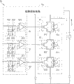
请参照图4所示,其为本实施例的发光装置2b的又一变化样式示意图。发光装置2b可以还包含一旁路开关电路6。Please refer to FIG. 4 , which is a schematic diagram of another variation of the
旁路开关电路6例如可包含一BJT或一MOSFET,在本实施例中,以包含MOSFET作说明。旁路开关电路6与发光电路4电连接,并与至少其中的一个发光单元41并联连接。在本实施例中,以旁路开关电路6与多个发光单元41并联连接作说明,然而这并非是限制性的。The
因此,当检测控制电路5b检测到发光电路4的功率、或电压、或电流小于等于一阈值,检测控制电路5b即可控制旁路开关电路6旁路导通电流I或关闭电源供应电路3,以停止供应电流I至发光电路4。另外,若检测控制电路5b为检测发光电路4的开关状态,同样地,当发光电路4的这些发光元件411为关闭状态时,检测控制电路5b可控制旁路开关电路6旁路导通电流I或关闭电源供应电路3,以停止供应电流I至发光电路4。Therefore, when the
值得一提的是,不论旁路开关电路6包含三端开关元件或四端开关元件,其导通时跨接于发光电路4的端电压小于发光电路4导通时的端电压。It is worth mentioning that, regardless of whether the
另外,检测控制电路5b还可包含一检测单元52及一电源控制单元53。In addition, the
检测单元52例如可包含逻辑门、或比较器、或电阻器、或电容器、或光传感器,其检测发光电路4的功率、或电压、或电流、或开关状态,以产生至少一反馈信号F。其中,功率例如为发光电路4的电功率或发光功率,电压或电流为发光电路4的端电压大小或电流大小,而开关状态为该等开关元件412的开关状态。反馈信号F例如可为数字信号或模拟信号。The detecting
电源控制单元53例如可具有逻辑门或比较器,其中,逻辑门例如为或(OR)门、或者与(AND)门。The
因此,当反馈信号F为模拟信号,电源控制单元53可具有逻辑门,而电源控制单元53会比较反馈信号F与一阈值。当反馈信号F小于等于阈值时,则电源控制单元53可控制旁路开关电路6旁路导通电流I,或关闭电源供应电路3,以停止供应电流I至发光电路4。Therefore, when the feedback signal F is an analog signal, the
另外,当检测单元52为输出多个数字的反馈信号F时(例如检测单元52为检测开关元件412的开关状态),电源控制单元53则可具有逻辑门。电源控制单元53可对这些反馈信号F进行或(OR)运算、或者与(AND)运算。依据运算结果,若发光电路4的这些发光元件411为关闭状态,则电源控制单元53可控制旁路开关电路6旁路导通电流I,或关闭电源供应电路3,以停止供应电流I至发光电路4。In addition, when the
综上所述,依据本发明的发光装置先通过检测控制电路检测发光电路的功率、或电压、或电流、或开关状态,而停止供应电流至发光电路。因此,本发明的发光装置可依据发光电路的状态,来对应地控制发光电路电源的供应,由此即可减少不必要的电能损耗与浪费。另外,发光装置还可包含旁路开关电路,由此检测控制电路除可关闭电源供应电路外,也可控制旁路开关电路旁路导通电流,以停止供应电流至发光电路。To sum up, the light emitting device according to the present invention first detects the power, voltage, current, or switch state of the light emitting circuit through the detection control circuit, and then stops supplying current to the light emitting circuit. Therefore, the light emitting device of the present invention can control the power supply of the light emitting circuit correspondingly according to the state of the light emitting circuit, thereby reducing unnecessary power loss and waste. In addition, the lighting device can also include a bypass switch circuit, so that the detection control circuit can not only turn off the power supply circuit, but also control the bypass switch circuit to bypass the conduction current, so as to stop supplying current to the lighting circuit.
另外,检测控制电路还可包含一检测单元及一电源控制单元。检测单元可产生数字或模拟的反馈信号,电源控制单元则可依据反馈信号来使电源供应电路停止供应电流至发光电路。In addition, the detection control circuit may further include a detection unit and a power control unit. The detection unit can generate a digital or analog feedback signal, and the power control unit can stop the power supply circuit from supplying current to the light emitting circuit according to the feedback signal.
以上所述仅为举例性,而非为限制性的。任何未脱离本发明的精神与范畴,而对其进行的等效修改或变更,均应包含于所附的权利要求范围中。The above description is for illustration only, not for limitation. Any equivalent modifications or changes made without departing from the spirit and scope of the present invention shall be included in the scope of the appended claims.
Claims (13)
Priority Applications (1)
| Application Number | Priority Date | Filing Date | Title |
|---|---|---|---|
| CN200810177768A CN101742786A (en) | 2008-11-18 | 2008-11-18 | light emitting device |
Applications Claiming Priority (1)
| Application Number | Priority Date | Filing Date | Title |
|---|---|---|---|
| CN200810177768A CN101742786A (en) | 2008-11-18 | 2008-11-18 | light emitting device |
Publications (1)
| Publication Number | Publication Date |
|---|---|
| CN101742786A true CN101742786A (en) | 2010-06-16 |
Family
ID=42465451
Family Applications (1)
| Application Number | Title | Priority Date | Filing Date |
|---|---|---|---|
| CN200810177768A Pending CN101742786A (en) | 2008-11-18 | 2008-11-18 | light emitting device |
Country Status (1)
| Country | Link |
|---|---|
| CN (1) | CN101742786A (en) |
-
2008
- 2008-11-18 CN CN200810177768A patent/CN101742786A/en active Pending
Similar Documents
| Publication | Publication Date | Title |
|---|---|---|
| US9672779B2 (en) | Liquid crystal display device, backlight module, and drive circuit for backlight source thereof | |
| TWI448198B (en) | System and method for dimming control under capacitive loads | |
| US8896288B2 (en) | TRIAC dimmer detection | |
| CN103747578B (en) | Led backlight drive circuit and liquid crystal display | |
| CN103680444B (en) | LED boost converter and apply its backlight LED drive unit | |
| WO2015027533A1 (en) | Backlight driving circuit and liquid crystal display device | |
| US20140252972A1 (en) | Led light source with reduced flicker | |
| CN103198809B (en) | LED (Light Emitting Diode) backlight source and liquid-crystal display equipment | |
| US9058776B2 (en) | LED backlight source and liquid crystal device | |
| CN103280191A (en) | LED (light-emitting diode) backlight driving circuit, LCD (liquid crystal display) device and driving method | |
| CN103563484A (en) | Brightness control for led lighting | |
| CN107770901A (en) | Light emitting diode driving device and short-circuit protection method of driving device | |
| CN204377201U (en) | A kind of constant current driver circuit for LED and LED automobile illumination device | |
| CN101871582A (en) | light emitting device | |
| TWI442811B (en) | Light source driving device | |
| CN104869686A (en) | Driving circuit and illuminating device comprising same | |
| CN103841707B (en) | Load driver associated with light-emitting diodes | |
| CN201765804U (en) | LED driver circuit with adjustable current and power | |
| CN101742786A (en) | light emitting device | |
| CN207367576U (en) | PWM dimming circuit, backlight module, liquid crystal display module and terminal | |
| CN203289708U (en) | A multi-loop current-limiting power supply circuit | |
| WO2009078468A1 (en) | Planar light-emitting module lighting circuit, and illuminating device | |
| CN220106005U (en) | Display backlight control circuit, circuit board, display screen and television | |
| CN216820156U (en) | A dimming control circuit and system | |
| US9196202B2 (en) | LED backlight driving circuit, LCD device, and method for driving the LED backlight driving circuit |
Legal Events
| Date | Code | Title | Description |
|---|---|---|---|
| C06 | Publication | ||
| PB01 | Publication | ||
| C10 | Entry into substantive examination | ||
| SE01 | Entry into force of request for substantive examination | ||
| C02 | Deemed withdrawal of patent application after publication (patent law 2001) | ||
| WD01 | Invention patent application deemed withdrawn after publication |
Application publication date: 20100616 |