CN100479232C - Electrode assembly and lithium ion secondary battery using the same - Google Patents
Electrode assembly and lithium ion secondary battery using the same Download PDFInfo
- Publication number
- CN100479232C CN100479232C CNB2005100797950A CN200510079795A CN100479232C CN 100479232 C CN100479232 C CN 100479232C CN B2005100797950 A CNB2005100797950 A CN B2005100797950A CN 200510079795 A CN200510079795 A CN 200510079795A CN 100479232 C CN100479232 C CN 100479232C
- Authority
- CN
- China
- Prior art keywords
- electrode
- positive
- plate
- electrode assembly
- negative electrode
- Prior art date
- Legal status (The legal status is an assumption and is not a legal conclusion. Google has not performed a legal analysis and makes no representation as to the accuracy of the status listed.)
- Expired - Lifetime
Links
Images


Classifications
-
- H—ELECTRICITY
- H01—ELECTRIC ELEMENTS
- H01M—PROCESSES OR MEANS, e.g. BATTERIES, FOR THE DIRECT CONVERSION OF CHEMICAL ENERGY INTO ELECTRICAL ENERGY
- H01M10/00—Secondary cells; Manufacture thereof
- H01M10/05—Accumulators with non-aqueous electrolyte
- H01M10/058—Construction or manufacture
- H01M10/0587—Construction or manufacture of accumulators having only wound construction elements, i.e. wound positive electrodes, wound negative electrodes and wound separators
-
- H—ELECTRICITY
- H01—ELECTRIC ELEMENTS
- H01M—PROCESSES OR MEANS, e.g. BATTERIES, FOR THE DIRECT CONVERSION OF CHEMICAL ENERGY INTO ELECTRICAL ENERGY
- H01M10/00—Secondary cells; Manufacture thereof
- H01M10/05—Accumulators with non-aqueous electrolyte
- H01M10/052—Li-accumulators
- H01M10/0525—Rocking-chair batteries, i.e. batteries with lithium insertion or intercalation in both electrodes; Lithium-ion batteries
-
- H—ELECTRICITY
- H01—ELECTRIC ELEMENTS
- H01M—PROCESSES OR MEANS, e.g. BATTERIES, FOR THE DIRECT CONVERSION OF CHEMICAL ENERGY INTO ELECTRICAL ENERGY
- H01M50/00—Constructional details or processes of manufacture of the non-active parts of electrochemical cells other than fuel cells, e.g. hybrid cells
- H01M50/50—Current conducting connections for cells or batteries
- H01M50/531—Electrode connections inside a battery casing
- H01M50/534—Electrode connections inside a battery casing characterised by the material of the leads or tabs
-
- H—ELECTRICITY
- H01—ELECTRIC ELEMENTS
- H01M—PROCESSES OR MEANS, e.g. BATTERIES, FOR THE DIRECT CONVERSION OF CHEMICAL ENERGY INTO ELECTRICAL ENERGY
- H01M50/00—Constructional details or processes of manufacture of the non-active parts of electrochemical cells other than fuel cells, e.g. hybrid cells
- H01M50/50—Current conducting connections for cells or batteries
- H01M50/531—Electrode connections inside a battery casing
- H01M50/536—Electrode connections inside a battery casing characterised by the method of fixing the leads to the electrodes, e.g. by welding
-
- H—ELECTRICITY
- H01—ELECTRIC ELEMENTS
- H01M—PROCESSES OR MEANS, e.g. BATTERIES, FOR THE DIRECT CONVERSION OF CHEMICAL ENERGY INTO ELECTRICAL ENERGY
- H01M50/00—Constructional details or processes of manufacture of the non-active parts of electrochemical cells other than fuel cells, e.g. hybrid cells
- H01M50/50—Current conducting connections for cells or batteries
- H01M50/531—Electrode connections inside a battery casing
- H01M50/538—Connection of several leads or tabs of wound or folded electrode stacks
-
- H—ELECTRICITY
- H01—ELECTRIC ELEMENTS
- H01M—PROCESSES OR MEANS, e.g. BATTERIES, FOR THE DIRECT CONVERSION OF CHEMICAL ENERGY INTO ELECTRICAL ENERGY
- H01M10/00—Secondary cells; Manufacture thereof
- H01M10/04—Construction or manufacture in general
- H01M10/0431—Cells with wound or folded electrodes
-
- Y—GENERAL TAGGING OF NEW TECHNOLOGICAL DEVELOPMENTS; GENERAL TAGGING OF CROSS-SECTIONAL TECHNOLOGIES SPANNING OVER SEVERAL SECTIONS OF THE IPC; TECHNICAL SUBJECTS COVERED BY FORMER USPC CROSS-REFERENCE ART COLLECTIONS [XRACs] AND DIGESTS
- Y02—TECHNOLOGIES OR APPLICATIONS FOR MITIGATION OR ADAPTATION AGAINST CLIMATE CHANGE
- Y02E—REDUCTION OF GREENHOUSE GAS [GHG] EMISSIONS, RELATED TO ENERGY GENERATION, TRANSMISSION OR DISTRIBUTION
- Y02E60/00—Enabling technologies; Technologies with a potential or indirect contribution to GHG emissions mitigation
- Y02E60/10—Energy storage using batteries
-
- Y—GENERAL TAGGING OF NEW TECHNOLOGICAL DEVELOPMENTS; GENERAL TAGGING OF CROSS-SECTIONAL TECHNOLOGIES SPANNING OVER SEVERAL SECTIONS OF THE IPC; TECHNICAL SUBJECTS COVERED BY FORMER USPC CROSS-REFERENCE ART COLLECTIONS [XRACs] AND DIGESTS
- Y02—TECHNOLOGIES OR APPLICATIONS FOR MITIGATION OR ADAPTATION AGAINST CLIMATE CHANGE
- Y02P—CLIMATE CHANGE MITIGATION TECHNOLOGIES IN THE PRODUCTION OR PROCESSING OF GOODS
- Y02P70/00—Climate change mitigation technologies in the production process for final industrial or consumer products
- Y02P70/50—Manufacturing or production processes characterised by the final manufactured product
Landscapes
- Chemical & Material Sciences (AREA)
- Chemical Kinetics & Catalysis (AREA)
- Electrochemistry (AREA)
- General Chemical & Material Sciences (AREA)
- Engineering & Computer Science (AREA)
- Manufacturing & Machinery (AREA)
- Materials Engineering (AREA)
- Secondary Cells (AREA)
- Battery Electrode And Active Subsutance (AREA)
- Connection Of Batteries Or Terminals (AREA)
Abstract
一种电极组件以及使用它的锂离子二次电池,能够防止在电极组件外周缘部分产生短路。正负极板的无涂层区域和在电极组件内外周缘部分中的活性物质层被优化排列,从而使得电极组件的厚度沿电极组件的横向方向均匀形成。

An electrode assembly and a lithium ion secondary battery using the same can prevent a short circuit from occurring at the outer peripheral portion of the electrode assembly. The uncoated areas of the positive and negative plates and the active material layers in the inner and outer peripheral portions of the electrode assembly are optimally arranged so that the thickness of the electrode assembly is uniformly formed along the lateral direction of the electrode assembly.
Description
本申请要求2004年6月28日递交于韩国知识产权局的韩国专利申请2004-0048994的优先权并由此受益,在此将其公开内容全部引入作为参考。This application claims priority from and benefits from Korean Patent Application 2004-0048994 filed with the Korean Intellectual Property Office on June 28, 2004, the disclosure of which is hereby incorporated by reference in its entirety.
技术领域 technical field
本发明涉及电极组件以及使用它的锂离子二次电池,更具体地,涉及一种能够防止在电极组件的外围部分产生短路的电极组件以及使用它的锂离子二次电池。The present invention relates to an electrode assembly and a lithium ion secondary battery using the same, and more particularly, to an electrode assembly capable of preventing a short circuit from occurring at a peripheral portion of the electrode assembly and a lithium ion secondary battery using the same.
背景技术 Background technique
本领域内公知的是,二次电池不同于早期电池,二次电池是可以充电和放电的电源。二次电池广泛地用于先进的便携式电子装置的电子技术领域,如便携式电话、笔记本电脑和可携式摄像机。It is well known in the art that a secondary battery is a power source that can be charged and discharged, unlike earlier batteries. Secondary batteries are widely used in the electronics field of advanced portable electronic devices, such as cellular phones, notebook computers, and camcorders.
特别是,锂离子二次电池具有的工作电压为大约3.7V,是用作便携式电子设备电源的Ni-Cd电池或Ni-MH电池的三倍。另外,锂离子二次电池具有较高的单位质量能量密度,因此锂二次电池广泛地应用于先进的电子技术领域。In particular, lithium ion secondary batteries have an operating voltage of about 3.7 V, which is three times higher than that of Ni-Cd batteries or Ni-MH batteries used as power sources for portable electronic devices. In addition, lithium-ion secondary batteries have high energy density per unit mass, so lithium secondary batteries are widely used in advanced electronic technology fields.
通常,锂离子二次电池以锂-氧化物作为正极活性物质,碳材料作为负极活性物质。另外,锂二次电池根据用于二次电池的电解液类型分为液体电解液电池和高聚合体电解液电池。使用液体电解液的二次电池称作“锂离子二次电池”,而使用高聚合体电解液的二次电池称作“锂聚合体二次电池”。另外,锂离子二次电池形成为不同的形状,如圆柱形锂离子二次电池、罐形锂离子二次电池和袋锂离子二次电池。Generally, lithium-ion secondary batteries use lithium-oxide as the positive electrode active material, and carbon materials as the negative electrode active material. In addition, lithium secondary batteries are classified into liquid electrolyte batteries and high polymer electrolyte batteries according to the type of electrolyte used for the secondary battery. A secondary battery using a liquid electrolyte is called a "lithium ion secondary battery", and a secondary battery using a high polymer electrolyte is called a "lithium polymer secondary battery". In addition, lithium ion secondary batteries are formed in various shapes, such as cylindrical lithium ion secondary batteries, can-shaped lithium ion secondary batteries, and pouch lithium ion secondary batteries.
如图1和2所示,典型的罐形锂离子蓄电池包括罐10,容纳在罐10中的电极组件20,用于密封罐10顶部开口的盖部件70。As shown in FIGS. 1 and 2 , a typical can-shaped lithium ion battery includes a can 10 , an
罐10由具有六面体形状的金属制成,并作为端子。该罐10包括上口部位10a,通过其电极组件20可以装入到罐10中。The can 10 is made of metal having a hexahedral shape, and serves as a terminal. The can 10 includes an opening portion 10a through which the
参见图2,电极组件20包括正极板30、负极板30以及隔板50。正极板30和负极板30以隔板50在其中间而卷绕成胶卷形。Referring to FIG. 2 , the
正极板30包括由铝材料制成的正极集电体32,和涂在正极集电体32内外表面上包含锂-基氧化物的正极活性物质层34。正极集电体32具有正极无涂层区域32a,其上的正极活性物质层34没有涂层,对应于正极板30的两端。正极接片36以超声波焊接固定在正极无涂层区域32a上,使得正极接片36的一端可以向上突出到正极集电体32的上端以外。正极接片36通常由Ni或Ni合金制成。不过正极接片36也可以使用其他金属材料制成。The
负极板30包括由薄片状铝箔制成的负极集电体42,和涂在负极集电体42内外表面上包含碳材料的负极活性物质层44。负极集电体42具有负极无涂层区域42a,其上的负极活性物质层44没有涂层,对应于负极板30的两端。负极接片46以超声波焊接固定在负极无涂层区域42a上,使得负极接片46的一端可以向上突出到负极集电体42的上端以外。负极接片46通常由Ni或Ni合金制成。不过负极接片46也可以使用其他金属材料制成。The
隔板50置于正极板30和负极板30之间,以使正极板30和负极板30之间绝缘。隔板50由聚乙烯、聚丙烯或聚乙烯和聚丙烯的混合物制成。在一个示范性实施例中,隔板50的宽度大于正极板30和负极板30的厚度,以有效地防止正极板30和负极板30之间的短路。The
盖部件70包括盖板71、绝缘板72、端子板73和负极端子74。盖部件70装入到单独的绝缘壳体79中后,与罐10的上口部位10a结合并将罐10密封。The cover member 70 includes a cover plate 71 , an insulating plate 72 , a terminal plate 73 and a negative terminal 74 . After the lid member 70 is housed in the separate insulating case 79, it is combined with the upper opening portion 10a of the can 10 to seal the can 10.
但是参见图2,电极组件20的正极接片36与正极板30和负极板30的正极活性物质层34和负极活性物质层44,在电极组件20的横向方向上互相交迭,这样电极组件20的厚度沿电极组件20的横向方向不均匀。也就是能够从图3中看出的,在电极组件20的横向方向上可能发生厚度变化。特别是图的左面显示出电极组件20的厚度相对于其它部分增加了很多。这是因为正极接片36可能在左面,与正极板30和负极板30的正极活性物质层34和负极活性物质层44在一边。这种情况下,很难均匀地将电极组件20卷绕成紧凑的形状,从而使装入到罐10的电极组件20不具有最佳的体积。由此也不能增加二次电池的能量密度。But referring to FIG. 2, the
另外,锂离子二次电池的能量密度增加后,在过充电/过放电或电极短路时产生的热量也会增加。特别的,负极接片46和正极接片36的负极板30和正极板30的焊接部位可能会与其他金属结合,负极板30和正极板30的焊接部位的内阻会增加,从而该焊接部位会产生大量的热量。如果热量产生于电极片的附近,用于使正极板绝缘于负极板的隔板可能会熔化和收缩。特别的,图2中接触于正极接片的零件产生大量的热,所以相邻于正极板的隔板的一端可能会明显地收缩。在各别情况下,沿负极板和正极板之间的隔板会消失。这样,正极板和负极板之间的短路会进一步产生。In addition, as the energy density of lithium-ion secondary batteries increases, the amount of heat generated during overcharge/overdischarge or short-circuiting of electrodes also increases. In particular, the welded portion of the
发明内容 Contents of the invention
由此,根据本发明,提供了一种电极组件以及使用它的锂离子二次电池,通过优化排列正负极板的无涂层区域,以及电极组件内外周缘部分的活性物质层,使得电极组件的厚度沿电极组件的横向方向均匀分布,从而使该组件具有防止在电极组件外周缘部分产生短路的功能。Thus, according to the present invention, an electrode assembly and a lithium-ion secondary battery using it are provided. By optimizing the uncoated areas of the positive and negative plates and the active material layers on the inner and outer peripheral parts of the electrode assembly, the electrode assembly The thickness of the electrode assembly is uniformly distributed along the lateral direction of the electrode assembly, so that the assembly has the function of preventing short circuit at the outer peripheral portion of the electrode assembly.
根据本发明的一方面,提供了一种电极组件,包括:包含正极集电体和正极活性物质层的正极板,在其两侧具有正极无涂层区域;包含负极集电体和负极活性物质层的负极板,在其两侧具有负极无涂层区域;用于使正极板绝缘于负极板的隔板;安装在正极无涂层区域的正极接片;以及安装在负极无涂层区域的负极接片,当正极板和负极板从电极组件的内周缘部分向外周缘部分卷绕时,从电极组件的横向方向看,形成于电极组件外周缘部分的负极板的负极活性物质层的端部,布置在电极组件内周缘部分的正极板的正极无涂层区域中。According to one aspect of the present invention, there is provided an electrode assembly, comprising: a positive electrode plate comprising a positive electrode current collector and a positive electrode active material layer, with a positive electrode uncoated area on both sides; comprising a negative electrode current collector and a negative electrode active material layered negative plate with a negative uncoated area on both sides; a separator for insulating the positive plate from the negative plate; a positive tab mounted on the positive uncoated area; and a Negative electrode tab, when the positive electrode plate and the negative electrode plate are wound from the inner peripheral portion of the electrode assembly to the outer peripheral portion, viewed from the lateral direction of the electrode assembly, the end of the negative electrode active material layer of the negative electrode plate formed on the outer peripheral portion of the electrode assembly portion, arranged in the positive electrode uncoated area of the positive electrode plate at the inner peripheral portion of the electrode assembly.
根据本发明的示范性实施例,从电极组件的横向方向看,形成于该电极组件内周缘部分的正极板的正极无涂层区域的端部,沿着与形成于电极组件外周缘部分的负极板的负极活性物质层的端部大致相同的方向对齐。According to an exemplary embodiment of the present invention, viewed from the lateral direction of the electrode assembly, the end of the positive electrode uncoated region of the positive electrode plate formed on the inner peripheral portion of the electrode assembly is aligned with the negative electrode formed on the outer peripheral portion of the electrode assembly. The ends of the negative electrode active material layers of the plates were aligned in substantially the same direction.
从电极组件的横向方向看,形成于布置在该电极组件外周缘部分的正极板的内外表面上的正极无涂层区域的端部,在形成于布置在该电极组件内周缘部分的负极集电体外表面的负极无涂层区域的内部对齐。Viewed from the lateral direction of the electrode assembly, at the end of the positive electrode uncoated area formed on the inner and outer surfaces of the positive electrode plate arranged at the outer peripheral portion of the electrode assembly, at the end of the negative electrode current collector formed at the inner peripheral portion of the electrode assembly The interior of the negative uncoated region of the in vitro surface is aligned.
根据本发明的示范性实施例,从电极组件的横向方向看,形成于布置在该电极组件内周缘部分的负极板的外表面的负极无涂层区域的端部,沿着与形成于布置在该电极组件外周缘部分的正极板的外表面的正极活性物质层的端部大致相同的方向对齐。According to an exemplary embodiment of the present invention, viewed from the lateral direction of the electrode assembly, the end of the negative electrode uncoated region formed on the outer surface of the negative electrode plate arranged at the inner peripheral portion of the electrode assembly is formed along the The ends of the positive electrode active material layer on the outer surface of the positive electrode plate at the outer peripheral portion of the electrode assembly are aligned in substantially the same direction.
根据本发明的示范性实施例,从电极组件的横向方向看,形成于布置在电极组件内周缘部分的负极集电体的外表面的负极无涂层区域的端部,沿着与布置在该电极组件外周缘部分的正极集电体的内表面的正极活性物质层的端部相同的方向对齐。According to an exemplary embodiment of the present invention, viewed from the lateral direction of the electrode assembly, the end of the negative electrode uncoated region formed on the outer surface of the negative electrode current collector arranged at the inner peripheral portion of the electrode assembly is arranged along the The ends of the positive electrode active material layer on the inner surface of the positive electrode current collector at the outer peripheral portion of the electrode assembly were aligned in the same direction.
根据本发明的示范性实施例,布置在该电极组件内周缘部分的正极板的正极无涂层区域的端部,与形成于负极板内外表面的负极无涂层区域的端部,在形成于布置在该电极组件内周缘部分的负极板的内外表面的负极活性物质层的内部,在电极组件的横向方向上具有预定距离的间隔。According to an exemplary embodiment of the present invention, the end of the positive electrode uncoated region of the positive electrode plate arranged at the inner peripheral portion of the electrode assembly, and the end of the negative electrode uncoated region formed on the inner and outer surfaces of the negative electrode plate are formed on the Inside the negative electrode active material layers arranged on the inner and outer surfaces of the negative electrode plate at the inner peripheral portion of the electrode assembly are spaced apart by a predetermined distance in the lateral direction of the electrode assembly.
根据本发明的示范性实施例,正极板的正极无涂层区域的端部,与负极板内外表面上形成的负极无涂层区域的端部间隔2到4mm。According to an exemplary embodiment of the present invention, the end of the positive uncoated area of the positive plate is spaced from the end of the negative uncoated area formed on the inner and outer surfaces of the negative plate by 2 to 4 mm.
根据本发明的示范性实施例,其中布置在该电极组件外周缘部分的负极板的负极无涂层区域的端部,与形成于正极板内外表面的正极活性物质层的端部,在形成于布置在该电极组件外周缘部分的正极板的内外表面的正极活无涂层区域内部,具有预定距离的间隔。According to an exemplary embodiment of the present invention, wherein the end of the negative electrode uncoated region of the negative electrode plate arranged on the outer peripheral portion of the electrode assembly and the end of the positive electrode active material layer formed on the inner and outer surfaces of the positive electrode plate are formed on the The inside of the positive electrode or uncoated area of the inner and outer surfaces of the positive plate arranged at the outer peripheral portion of the electrode assembly is spaced apart by a predetermined distance.
根据本发明的示范性实施例,正极板的正极活性物质层的端部,与形成在正极板内外表面上的正极活性物质层的端部间隔2到4mm。According to an exemplary embodiment of the present invention, the end of the positive active material layer of the positive plate is separated from the end of the positive active material layer formed on the inner and outer surfaces of the positive plate by 2 to 4 mm.
根据本发明的示范性实施例,正极接片形成于布置在电极组件外周缘部分的正极板的正极无涂层区域上,并与形成于电极组件内周缘部分的正极板的正极无涂层区域的端部,在正极板的正极活性物质层方向上间隔预定的距离。According to an exemplary embodiment of the present invention, the positive electrode tab is formed on the positive electrode uncoated area of the positive electrode plate arranged at the outer peripheral portion of the electrode assembly, and is connected with the positive electrode uncoated area of the positive electrode plate formed at the inner peripheral portion of the electrode assembly. The ends of the positive electrode plate are separated by a predetermined distance in the direction of the positive electrode active material layer.
根据本发明的示范性实施例,正极接片形成于正极无涂层区域的内表面或外表面上。According to an exemplary embodiment of the present invention, the positive electrode tab is formed on the inner surface or the outer surface of the uncoated region of the positive electrode.
根据本发明的示范性实施例,其中正极接片在电极组件的横向方向上,与布置在电极组件内周缘部分的正极板的正极无涂层区域相对。According to an exemplary embodiment of the present invention, wherein the positive tab is opposite to the positive uncoated area of the positive plate disposed at the inner peripheral portion of the electrode assembly in a lateral direction of the electrode assembly.
根据本发明的示范性实施例,布置在电极组件外周缘部分的负极板的负极无涂层区域,从负极板的负极活性物质层的端部延伸预定的宽度。According to an exemplary embodiment of the present invention, the negative electrode uncoated region of the negative electrode plate disposed at the outer peripheral portion of the electrode assembly extends a predetermined width from the end of the negative electrode active material layer of the negative electrode plate.
根据本发明的示范性实施例,负极无涂层区域的端部形成于预定的区域,在该区域中电极组件的外周缘部分以直线地形成。According to an exemplary embodiment of the present invention, the end of the negative electrode uncoated region is formed in a predetermined region where the outer peripheral portion of the electrode assembly is formed in a straight line.
根据本发明的示范性实施例,负极板的负极无涂层区域宽度为2mm到4mm。According to an exemplary embodiment of the present invention, the width of the negative electrode uncoated area of the negative electrode plate is 2 mm to 4 mm.
为了实现上述目的,根据本发明的另一方面,提供一种锂离子二次电池,包括:电极组件,包括负极板、正极板和使负极板绝缘于正极板的隔板;容纳该电极组件的罐体;以及包括密封罐体上口部位的盖板的盖部件,以及插入到形成于盖板上的端子孔中并保持绝缘的电极端子,其中该电极组件包括:包含正极集电体的正极板,该正极板具有第一表面、第二表面以及形成于该第一表面和第二表面上的正极活性物质层与没有该正极活性物质的正极无涂层区域;包含负极集电体的负极板,该负极板具有第一表面、第二表面以及形成于该第一表面和第二表面上的负极活性物质层与没有该负极活性物质的负极无涂层区域;用于将该正极板与该负极板绝缘的隔板;固定到该正极无涂层区域的正极接片;以及固定到该负极无涂层区域的负极接片,其中,当该正极板和负极板从该电极组件的内周缘部分向外周缘部分卷绕时,当从该电极组件的横向方向看,形成于该电极组件外周缘部分的负极板的负极活性物质层的端部,布置在形成于该电极组件内周缘部分的正极板的正极无涂层区域中。In order to achieve the above object, according to another aspect of the present invention, a lithium ion secondary battery is provided, comprising: an electrode assembly including a negative plate, a positive plate, and a separator for insulating the negative plate from the positive plate; a can body; and a cover member including a cover plate sealing an upper mouth portion of the can body, and an electrode terminal inserted into a terminal hole formed on the cover plate and kept insulated, wherein the electrode assembly includes: a positive electrode including a positive electrode current collector Plate, the positive electrode plate has a first surface, a second surface and a positive electrode active material layer formed on the first surface and the second surface and a positive electrode uncoated region without the positive electrode active material; a negative electrode comprising a negative electrode current collector A plate, the negative plate has a first surface, a second surface, a negative active material layer formed on the first surface and the second surface, and a negative uncoated area without the negative active material; The negative plate insulating separator; the positive tab fixed to the positive uncoated area; and the negative tab fixed to the negative uncoated area, wherein, when the positive plate and the negative plate are removed from the inside of the electrode assembly When the peripheral portion is wound toward the outer peripheral portion, when viewed from the lateral direction of the electrode assembly, the end of the negative electrode active material layer of the negative electrode plate formed on the outer peripheral portion of the electrode assembly is arranged on the inner peripheral portion of the electrode assembly. in the positive uncoated area of the positive plate.
附图说明 Description of drawings
图1为常规锂离子二次电池的分解透视图。FIG. 1 is an exploded perspective view of a conventional lithium ion secondary battery.
图2为常规电极组件的平面图。Fig. 2 is a plan view of a conventional electrode assembly.
图3为图2中沿电极组件横向方向的厚度变化图。FIG. 3 is a diagram of thickness variation along the lateral direction of the electrode assembly in FIG. 2 .
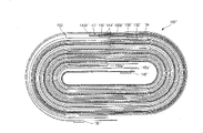
图4为根据本发明一个实施例的电极组件的平面图。FIG. 4 is a plan view of an electrode assembly according to one embodiment of the present invention.
图5为根据本发明另一个实施例的电极组件的平面图。FIG. 5 is a plan view of an electrode assembly according to another embodiment of the present invention.
图6为图4中沿电极组件横向方向的厚度变化图。FIG. 6 is a diagram of thickness variation along the lateral direction of the electrode assembly in FIG. 4 .
具体实施方式 Detailed ways
参见图1和4,根据本发明的锂离子二次电池包括罐10、在罐10中的电极组件100(代替现有计数中的电极组件20),用于密封罐10上口部位的盖部件70。以下,相同参照数表示常规二次电池中相同或类似的组件。Referring to Fig. 1 and 4, lithium ion secondary battery according to the present invention comprises can 10, the
参见图1,罐10由具有六面体形状的金属制成,以作为端子。该罐10包括上口部位10a,通过其电极组件100可以装入到罐10中。Referring to FIG. 1, a can 10 is made of metal having a hexahedral shape as a terminal. The can 10 includes an upper mouth portion 10a through which the
盖部件70包括盖板71、绝缘板72、端子板23和负极端子74。负极端子74固定地插入到盖板71上形成的端子孔中并保持绝缘。盖部件70装入到单独的绝缘壳体79中后,与罐10的上口部位10a结合并将罐10密封。The cover member 70 includes a cover plate 71 , an insulating plate 72 , a terminal plate 23 and a negative terminal 74 . The negative terminal 74 is fixedly inserted into a terminal hole formed on the cap plate 71 and kept insulated. After the lid member 70 is housed in the separate insulating case 79, it is combined with the upper opening portion 10a of the can 10 to seal the can 10.
参见图4,电极组件100包括正极板130、负极板140以及隔板150。正极板130和负极板140与插入其中的隔板150卷绕成胶卷配置。Referring to FIG. 4 , the
在以下的说明中,当电极组件已经被卷绕时,电极组件的中心部位称作“内周缘部分”,电极组件的外部分称作“外周缘部分”。所以,内周缘部分与外周缘部分是相对的。In the following description, when the electrode assembly has been wound, the central portion of the electrode assembly is referred to as an "inner peripheral portion", and the outer portion of the electrode assembly is referred to as an "outer peripheral portion". Therefore, the inner peripheral portion is opposed to the outer peripheral portion.
在电极组件100的内周缘部分具有负极接片146,其焊接在负极板140的负极无涂层区域,并向上伸出到电极组件100的上部以外。另外,在电极组件100的外周缘部分具有正极接片136,其焊接在正极板130的正极无涂层区域,并向上伸出到电极组件100的上部以外。正极接片136的位置可以与负极接片146的位置相替换。There is a
正极板130包括正极集电体132,正极活性物质层134以及正极接片136。The
正极集电体132由厚度范围在10到30μm之间的薄片状铝箔制成。正极集电体132的内外表面上形成正极活性物质层134,其主要由锂-基氧化物构成。另外,没有涂正极活性物质层134的正极无涂层区域133a和正极无涂层区域133b,形成于正极集电体132的内外表面上。但是,在电极组件100的预定外侧区域,只有正极集电体132的一侧表面具有正极活性物质层134,在正极集电体132的另一表面具有正极无涂层区域133b。在正极集电体132的内外表面上所涂正极活性物质层134的厚度范围在60到100μm。The positive electrode
正极接片136通过激光焊接或电阻焊接固定在形成于正极板130一端的正极无涂层区域上。正极接片136由Ni制成,正极接片136的上端向上伸出到正极集电体132的上端以外。正极接片136的厚度最好为80到120μm。The
负极板140包括负极收集器142、负极活性物质层144、负极接片146以及负极绝缘片148。The
负极集电体142由厚度范围在10到30μm的薄片状铝箔制成。负极集电体142的内外表面上形成负极活性物质层144,其主要由碳物质构成。另外,没有负极活性物质层144的负极无涂层区域143a和负极无涂层区域143b,形成于负极集电体142的内外表面上。但是,在电极组件100的预定内侧区域,只有负极集电体142的一侧表面具有负极活性物质层144,在负极集电体142的另一表面具有负极无涂层区域143a。在负极集电体142的内外表面上所涂负极活性物质层144的厚度范围在80到100μm之间。The
负极接片146由Ni制成,通过激光焊接或电阻焊接固定在布置在电极组件100内周缘部分的负极板140上。负极接片146的上端向上伸出到负极集电体142的上端以外。在一个示范性实施例中,负极接片146的厚度为80到120μm。The
参见图4,隔板150布置在正极板130和负极板140之间,从而在卷绕以形成电极组件100时,将正极板130绝缘于负极板140。Referring to FIG. 4 , the
以下将分别更加详细地说明正极活性物质层134和负极活性物质层144在电极组件100的正极板130和负极板140中的位置。需要指出的是电极组件100是从内周缘部分向外周缘部分卷绕的。The positions of the positive electrode
预定基准线“a”和“b”垂直于电极组件100的横向方向。基准线“a”和“b”用来准确地解释无涂层区域和活性物质层的关系,形成电极组件100后,其分别形成于电极组件100的内周缘部分和外周缘部分。The predetermined reference lines 'a' and 'b' are perpendicular to the lateral direction of the
另外,对着电极组件100的中心部位的正极板130和负极板140的表面参照为“内表面”,对着正极板130和负极板140内表面的表面参照为“外表面”。In addition, the surfaces of the
首先介绍形成于布置在电极组件100内周缘部分的正极板130的正极无涂层区域133a,与形成于电极组件100外周缘部分的负极板140的负极活性物质层144的端部的位置。Firstly, the position of the positive electrode
布置在电极组件100内周缘部分的正极板130包括正极无涂层区域133a,其形成于正极板130和负极板140之间,以预定宽度形成于正极集电体132的内外表面上。在一个示范性实施例中,正极板130的正极无涂层区域133a的宽度至少为2mm。正极无涂层区域133a的宽度小于2mm,在形成正极板130的正极集电体132上的正极活性物质层134时,正极活性物质层134有可能超出正极集电体132之外,从而造成活性物质的浪费。The
在正极板130和负极板140从电极组件100的内周缘部分向外周缘部分卷绕时,形成于电极组件100外周缘部分的负极板140的负极活性物质层144的端部,形成于布置在电极组件100内周缘部分的正极板130的正极无涂层区域133a内。具体讲,负极板140的负极活性物质层144的端部布置在电极组件100的内周缘部分的正极板130的正极无涂层区域133a的端部(基准线“a”),和正极板130的端部之间。在一个示范性实施例中,负极板140的负极活性物质层144的端部和正极板130的正极无涂层区域133a的端部最好以基准线“a”共线。这样,电极组件100的厚度变化可以变得最小,同时正极活性物质层134和负极活性物质层144的面积最大。When the
下面介绍形成于布置在电极组件100内周缘部分的负极板140的负极无涂层区域143a的端部,与形成于电极组件100外周缘部分的正极板130的正极活性物质层134的端部的位置。The difference between the end portion of the negative electrode
布置在电极组件100内周缘部分的负极板140从电极组件100的内周缘部分伸出预定距离,负极无涂层区域143a形成于负极板140的负极集电体142的内外表面上。因为负极接片146安装在负极无涂层区域143a上,所以负极无涂层区域143a必须具有足够的宽度以在其上安装负极接片146。负极无涂层区域143a从负极板140的端部伸出预定距离。参见图4,负极无涂层区域143a形成于负极集电体142的内外表面上,在负极集电体142的端部和基准线“b”之间的区域中。在基准线“b”上,负极活性物质层144形成于负极集电体142的外表面上,负极无涂层区域143a形成于负极集电体142的内表面上。当负极板140一次卷绕时,在负极集电体142的内表面上没有负极无涂层区域143a,负极活性物质层144从基准线b形成于负极集电体142的内外表面上。所以,当从电极组件100的横向方向上看时,形成于负极板140的内表面上的负极无涂层区域143a的端部,和形成于负极板140的外表面上的负极无涂层区域143a的端部同时结束于基准线b。The
在正极板130布置在电极组件100外周缘部分的情况下,当从电极组件100的横向方向看时,在布置在电极组件100最外端部位前面的正极集电体132的外表面上,正极活性物质层134的端部布置在电极组件100内周缘部分的负极板140的外表面上形成的负极无涂层区域143a内。另外,当从电极组件100的横向方向看时,在电极组件100最外端部位的正极集电体132的内表面上,正极活性物质层134的端部布置在电极组件100内周缘部分的负极板140的外表面上形成的负极无涂层区域143a内。In the case where the
所以,形成于布置在电极组件100外周缘部分的正极板130的内外表面上的正极无涂层区域133b的开始部位,即正极板130的正极活性物质层134的端部形成于布置在电极组件100内周缘部分的负极板140外表面的负极无涂层区域143a中。当从电极组件100的横向方向看时,形成于布置在电极组件100外周缘部分的正极集电体132外表面上的正极活性物质层134的端部,和形成于正极集电体132内表面的正极活性物质层134的端部,最好在相同的位置上,即布置在电极组件100内周缘部分的负极板140外表面上形成的负极无涂层区域143a的端部。也就是说,正极集电体132外表面上的正极活性物质层134的端部,正极集电体132内表面的正极活性物质层134的端部,以及电极组件100内周缘部分的负极板140外表面上形成的负极无涂层区域143a的端部都布置在基准线“b”内。这样,电极组件100的厚度变化可以变得最小,同时正极活性物质层134和负极活性物质层144的面积最大。Therefore, the beginning of the positive electrode
另外,基准线“b”与基准线“a”相隔预定距离。所以,布置在电极组件100内周缘部分的正极板130的正极无涂层区域133a的端部,与布置在电极组件100内周缘部分的负极集电体142的内外表面的负极无涂层区域的端部相隔。在一个示范性实施例中,正极无涂层区域133a的端部与负极无涂层区域143a的端部间隔预定的2到4mm。如果正极无涂层区域133a端部与负极无涂层区域143a端部的距离小于2mm,当正极板130和负极板140一起卷绕时,正极活性物质层134可能直接接触于负极板140的负极无涂层区域143a。另外,如果正极无涂层区域133a的端部与负极无涂层区域143a的端部之间的距离大于4mm,正极活性物质层134的尺寸将变小,从而降低二次电池的容量。In addition, the reference line "b" is separated from the reference line "a" by a predetermined distance. Therefore, the end portion of the positive electrode
另外,在电极组件100外周缘部分的负极活性物质层144的端部,布置在在电极组件外周缘部分的正极板130的内外表面上的正极无涂层区域133b内,并与正极板130内外表面上的正极活性物质层134的端部间隔一定距离。在一个示范性实施例中,负极板140的负极活性物质层144的端部与正极板130的正极活性物质层134的端部间隔2到4mm。如果负极活性物质层144的端部与正极活性物质层134的端部的距离小于2mm,当正极板130和负极板140一起卷绕时,正极活性物质层134可能直接接触于负极板140的负极无涂层区域143a。另外,如果正极活性物质层134的端部与负极活性物质层144的端部之间的距离大于4mm,正极活性物质层134的尺寸将变小,从而降低二次电池的容量。In addition, the end of the negative electrode
可以通过进一步绕着电极组件100卷绕正极板130一半,形成正极板130的正极无涂层区域133b。The positive electrode
正极接片136安装在布置在电极组件100外周缘部分的正极板130上的正极无涂层区域133b上,并与布置在电极组件100内周缘部分的正极板130的正极无涂层区域133a的端部,在正极板130的正极活性物质层134的方向间隔预定的距离。同时,正极接片136可以在正极无涂层区域133b的外表面的内表面上形成。从电极组件100的横向方向看,在一个示范性实施例中,正极接片136对着布置在电极组件100内周缘部分的正极板130的正极无涂层区域133a。正极板130的正极无涂层区域133b可以将电极组件100的内周缘部分产生的热量传递到外部,所以正极无涂层区域133b具有足够的长度来将热量传递到外部。The
负极接片146可以形成于布置在电极组件100内周缘部分的负极板140的外表面的负极无涂层区域143b的外表面的内表面上。The
根据以上结构的电极组件100,正极板130和负极板140的无涂层区域的开始部分,相同于正极板130和负极板140的正极活性物质层134和负极活性物质层144的结束部分。所以电极组件100的厚度可以均匀地形成。According to the
尽管图4所示的基准线“a”和“b”对准于电极组件100的中心部位,但是基准线“a”和“b”可以从电极组件100的中心部位移开预定的距离。这样,正极板130和负极板140相对于正极板130和负极板140的正极活性物质层134和负极活性物质层144的位置分别没有改变。Although the reference lines 'a' and 'b' shown in FIG. 4 are aligned to the central portion of the
图5为根据本发明另一个实施例的电极组件的上视图。以下在比较与图4中电极组件不同点的基础上来说明图5中的电极组件。FIG. 5 is a top view of an electrode assembly according to another embodiment of the present invention. The electrode assembly in FIG. 5 will be described below on the basis of comparing the differences with the electrode assembly in FIG. 4 .
参见图5,电极组件100′包括布置在电极组件100′外周缘部分的负极板140′,和具有相对较小宽度的负极无涂层区域143b′。在一个示范性实施例中,负极板140′的负极无涂层区域143b′的宽度距负极板140′的负极活性物质层144′的端部2到4mm。如果负极板140′的负极无涂层区域143b′的宽度小于2mm,在形成负极集电体142′上的负极活性物质层144′时,负极活性物质层144′可能会形成于负极集电体142′之外。另外,如果负极板140′的负极无涂层区域143b′的宽度大于4mm,则负极无涂层区域143b′不必要的延长到这样的长度。Referring to FIG. 5, the electrode assembly 100' includes a negative plate 140' disposed at an outer peripheral portion of the electrode assembly 100', and a negative
隔板150′可以从电极组件100′的内周缘部分延伸到正极板130′的端部。The separator 150' may extend from an inner peripheral portion of the electrode assembly 100' to an end of the positive electrode plate 130'.
由此,由正极板130′所造成的电极组件100′的增加的厚度可以被减小。另外,即便隔板150′由于二次电池所产生的热量而收缩,负极板140′的负极无涂层区域143b′也不会露出。Thus, an increased thickness of the electrode assembly 100' caused by the positive plate 130' may be reduced. In addition, even if the separator 150' shrinks due to heat generated by the secondary battery, the negative electrode
以下将根据示范性实施例说明根据本发明的电极组件的运行。The operation of the electrode assembly according to the present invention will be described below according to an exemplary embodiment.
参见图6,不同于常规电极组件(见图3),本发明的示范性电极组件100的厚度没有明显的变化。也就是说,电极组件100的厚度在电极组件100的横向方向上均匀地形成,而没有明显的厚度变化。Referring to FIG. 6, unlike the conventional electrode assembly (see FIG. 3), the thickness of the
另外,因为使用该电极组件100的锂离子二次电池的厚度可以在厚度方向均匀地形成,所以锂离子二次电池外形,特别是锂离子二次电池的厚度可以很容易地控制。In addition, since the thickness of the lithium ion secondary battery using the
尽管本发明是以胶卷类型的电极组件的罐状电极组件来说明的,但本发明也适用于使用胶卷类型的电极组件的方形二次电池,以及袋状二次电池。Although the present invention is described with a can-shaped electrode assembly of a jelly-roll type electrode assembly, the present invention is also applicable to a prismatic secondary battery using a jelly-roll type electrode assembly, and a pouch-shaped secondary battery.
根据本发明的示范性实施例,对用于二次电池中的电极组件的内外周缘部分的无涂层区域和活性物质层最优的排列,使得电极组件的厚度可以在横向方向上均匀地形成。According to an exemplary embodiment of the present invention, the uncoated region and the active material layer of the inner and outer peripheral portion of the electrode assembly used in the secondary battery are optimally arranged so that the thickness of the electrode assembly can be uniformly formed in the lateral direction .
另外根据本发明的示范性实施例,电极组件外周缘部分上形成的负极板的负极无涂层区域的长度可以减小,所以即便隔板由于正极接片附近所产生的热量而收缩,也可以避免负极板和正极板之间发生短路,从而提高了二次电池的稳定性。Also according to the exemplary embodiment of the present invention, the length of the negative electrode uncoated region of the negative electrode plate formed on the outer peripheral portion of the electrode assembly can be reduced, so even if the separator shrinks due to heat generated near the positive electrode tab, it can A short circuit between the negative plate and the positive plate is avoided, thereby improving the stability of the secondary battery.
尽管以上对示范性实施例以说明为目的进行了描述,但对于本领域技术人员可以理解,在不背离本发明权利要求所提出的范围和思路的情况下,本发明可以有各种改变、添加和替换。Although the exemplary embodiments have been described above for the purpose of illustration, it can be understood by those skilled in the art that various changes and additions can be made to the present invention without departing from the scope and spirit of the claims of the present invention. and replace.
Claims (17)
Applications Claiming Priority (2)
| Application Number | Priority Date | Filing Date | Title |
|---|---|---|---|
| KR20040048994 | 2004-06-28 | ||
| KR1020040048994A KR100601504B1 (en) | 2004-06-28 | 2004-06-28 | Electrode assembly and lithium ion secondary battery using same |
Publications (2)
| Publication Number | Publication Date |
|---|---|
| CN1722495A CN1722495A (en) | 2006-01-18 |
| CN100479232C true CN100479232C (en) | 2009-04-15 |
Family
ID=35541739
Family Applications (1)
| Application Number | Title | Priority Date | Filing Date |
|---|---|---|---|
| CNB2005100797950A Expired - Lifetime CN100479232C (en) | 2004-06-28 | 2005-06-28 | Electrode assembly and lithium ion secondary battery using the same |
Country Status (4)
| Country | Link |
|---|---|
| US (2) | US7638238B2 (en) |
| JP (1) | JP4971599B2 (en) |
| KR (1) | KR100601504B1 (en) |
| CN (1) | CN100479232C (en) |
Families Citing this family (24)
| Publication number | Priority date | Publication date | Assignee | Title |
|---|---|---|---|---|
| JP4412304B2 (en) | 2006-05-17 | 2010-02-10 | ソニー株式会社 | Secondary battery |
| US7867553B2 (en) * | 2006-08-23 | 2011-01-11 | The Gillette Company | Method of making cathode including iron disulfide |
| JP4630855B2 (en) * | 2006-09-22 | 2011-02-09 | トヨタ自動車株式会社 | Battery pack and manufacturing method thereof |
| KR100876268B1 (en) * | 2007-10-09 | 2008-12-26 | 삼성에스디아이 주식회사 | Lithium secondary battery |
| NZ584315A (en) * | 2007-10-19 | 2012-05-25 | Eveready Battery Inc | Lithium-iron disulfide cell design comprising a jellyroll electrode |
| JP4835956B2 (en) | 2008-07-02 | 2011-12-14 | トヨタ自動車株式会社 | battery |
| KR20110017761A (en) * | 2009-08-14 | 2011-02-22 | 에스비리모티브 주식회사 | Electrode plate for secondary battery and secondary battery comprising same |
| CA2770360C (en) * | 2009-08-27 | 2018-03-06 | Eveready Battery Company, Inc. | Lithium-iron disulfide cathode formulation having high pyrite content and low conductive additives |
| KR101174889B1 (en) | 2009-11-17 | 2012-08-17 | 삼성에스디아이 주식회사 | Secondary battery providing improved jelly roll structure of electrode assembly |
| KR101156331B1 (en) * | 2010-01-26 | 2012-06-13 | 에스비리모티브 주식회사 | Electrode assembly, method for fabricating the electrode assembly and secondary battery including the electrode assembly |
| CN102332613A (en) * | 2010-12-31 | 2012-01-25 | 东莞新能源科技有限公司 | A kind of winding method of square lithium ion battery |
| WO2012135500A1 (en) | 2011-03-29 | 2012-10-04 | The General Hospital Corporation | Engineered thioredoxin-like fold proteins |
| CN103050736A (en) * | 2011-10-14 | 2013-04-17 | 深圳市海盈科技有限公司 | Assembly method of lithium ion battery |
| KR101615712B1 (en) * | 2011-11-11 | 2016-04-26 | 주식회사 엘지화학 | Electrode assembly and secondary battery having the same |
| KR101439834B1 (en) | 2012-11-08 | 2014-09-17 | 주식회사 엘지화학 | Flexible jelly roll type secondary battery |
| KR101666873B1 (en) | 2012-11-23 | 2016-10-17 | 삼성에스디아이 주식회사 | Electrode assembly, and rechargeable battery having thereof |
| US20140370345A1 (en) * | 2013-06-12 | 2014-12-18 | Motorola Mobility Llc | Segmented energy storage assembly |
| KR102277352B1 (en) * | 2016-08-24 | 2021-07-14 | 삼성에스디아이 주식회사 | Electrode assembly and rechargeable battery including the same |
| KR102654626B1 (en) * | 2016-10-27 | 2024-04-04 | 삼성에스디아이 주식회사 | Secondary battery |
| WO2019064806A1 (en) * | 2017-09-29 | 2019-04-04 | パナソニック株式会社 | Non-aqueous electrolyte secondary battery |
| KR102702546B1 (en) | 2018-02-14 | 2024-09-05 | 삼성에스디아이 주식회사 | Electrode assembly and secondary battery comprising the same |
| KR102897462B1 (en) * | 2019-11-19 | 2025-12-09 | 주식회사 엘지에너지솔루션 | Apparatus and method of manufacturing electrode assembly |
| KR102583022B1 (en) * | 2021-05-25 | 2023-10-04 | 주식회사 바올테크 | Apparatus for electrode positioning of secondary battery |
| CN120391002A (en) * | 2023-07-07 | 2025-07-29 | 株式会社Lg新能源 | Electrode assembly and secondary battery including the same |
Family Cites Families (8)
| Publication number | Priority date | Publication date | Assignee | Title |
|---|---|---|---|---|
| US5989743A (en) * | 1994-09-27 | 1999-11-23 | Asahi Kasei Kogyo Kabushiki Kaisha | Non-aqueous battery |
| US6027835A (en) * | 1996-12-11 | 2000-02-22 | Fuji Film Celltec Co., Ltd. | Cell electrode sheet with displaced electrode depolarizing mixes |
| JP3428448B2 (en) * | 1998-08-21 | 2003-07-22 | 三菱電機株式会社 | Electrode structure and battery using the same |
| JP3750490B2 (en) * | 2000-06-01 | 2006-03-01 | 三菱電機株式会社 | battery |
| JP2003086233A (en) * | 2001-09-07 | 2003-03-20 | Mitsubishi Electric Corp | Flat battery and its manufacturing method |
| JP3661945B2 (en) * | 2002-07-24 | 2005-06-22 | ソニー株式会社 | Positive electrode for secondary battery and secondary battery provided with the same |
| KR100449763B1 (en) * | 2002-09-11 | 2004-09-22 | 삼성에스디아이 주식회사 | Cap assembly and secondary battery applying the same |
| JP2004139823A (en) * | 2002-10-17 | 2004-05-13 | Sony Corp | Composition for electrolyte, polymer electrolyte and battery using the same |
-
2004
- 2004-06-28 KR KR1020040048994A patent/KR100601504B1/en not_active Expired - Lifetime
-
2005
- 2005-06-20 JP JP2005179633A patent/JP4971599B2/en not_active Expired - Lifetime
- 2005-06-28 US US11/170,763 patent/US7638238B2/en not_active Ceased
- 2005-06-28 CN CNB2005100797950A patent/CN100479232C/en not_active Expired - Lifetime
-
2010
- 2010-11-11 US US12/944,668 patent/USRE42696E1/en active Active
Also Published As
| Publication number | Publication date |
|---|---|
| CN1722495A (en) | 2006-01-18 |
| US20060008701A1 (en) | 2006-01-12 |
| US7638238B2 (en) | 2009-12-29 |
| JP4971599B2 (en) | 2012-07-11 |
| KR20060000100A (en) | 2006-01-06 |
| JP2006012813A (en) | 2006-01-12 |
| KR100601504B1 (en) | 2006-07-19 |
| USRE42696E1 (en) | 2011-09-13 |
Similar Documents
| Publication | Publication Date | Title |
|---|---|---|
| CN100479232C (en) | Electrode assembly and lithium ion secondary battery using the same | |
| KR100635761B1 (en) | Electrode assembly and secondary battery using same | |
| US7585589B2 (en) | Pouch-type lithium secondary battery | |
| US8906543B2 (en) | Battery having tab with insulator for electrode assembly | |
| CN101271985B (en) | Rechargeable battery and manufacturing method thereof | |
| KR101379985B1 (en) | Electrode assembly and secondary battery using the same | |
| CN100483799C (en) | Secondary battery | |
| CN100474656C (en) | Battery | |
| CN101546820B (en) | Protective circuit board and battery pack using the same | |
| JP3492262B2 (en) | Sealed battery | |
| US8927126B2 (en) | Protection circuit assembly and battery pack having the same | |
| CN101459229B (en) | Insulating case for secondary battery and secondary battery using the same | |
| JP2004356085A (en) | Jelly roll type electrode assembly and secondary battery using this | |
| US9012070B2 (en) | Secondary battery | |
| US9508973B2 (en) | Secondary battery | |
| KR20040022713A (en) | Pouched-type case and lithium secondary battery applying the same | |
| KR100591435B1 (en) | Can-type Lithium-ion Secondary Battery | |
| KR100889767B1 (en) | Lithium secondary battery having protection plate | |
| KR100635760B1 (en) | Jelly roll type electrode assembly and secondary battery having same | |
| CN116508187A (en) | Electrode tab, electrode assembly and secondary battery including the electrode assembly |
Legal Events
| Date | Code | Title | Description |
|---|---|---|---|
| C06 | Publication | ||
| PB01 | Publication | ||
| C10 | Entry into substantive examination | ||
| SE01 | Entry into force of request for substantive examination | ||
| C14 | Grant of patent or utility model | ||
| GR01 | Patent grant | ||
| CX01 | Expiry of patent term | ||
| CX01 | Expiry of patent term |
Granted publication date: 20090415 |